EP0958679B1 - System zur parameteranalyse und verkehrsüberwachung in atm-netzen - Google Patents
System zur parameteranalyse und verkehrsüberwachung in atm-netzen Download PDFInfo
- Publication number
- EP0958679B1 EP0958679B1 EP97903578A EP97903578A EP0958679B1 EP 0958679 B1 EP0958679 B1 EP 0958679B1 EP 97903578 A EP97903578 A EP 97903578A EP 97903578 A EP97903578 A EP 97903578A EP 0958679 B1 EP0958679 B1 EP 0958679B1
- Authority
- EP
- European Patent Office
- Prior art keywords
- atm
- connection
- atm connection
- connections
- traffic
- Prior art date
- Legal status (The legal status is an assumption and is not a legal conclusion. Google has not performed a legal analysis and makes no representation as to the accuracy of the status listed.)
- Expired - Lifetime
Links
- 238000012544 monitoring process Methods 0.000 title claims abstract description 24
- 238000004458 analytical method Methods 0.000 title claims description 63
- 238000012546 transfer Methods 0.000 title description 5
- 238000000034 method Methods 0.000 claims abstract description 56
- 230000006870 function Effects 0.000 claims description 17
- 230000011664 signaling Effects 0.000 claims description 14
- 238000012545 processing Methods 0.000 claims description 5
- 238000012512 characterization method Methods 0.000 claims 1
- 239000000523 sample Substances 0.000 description 38
- 239000011159 matrix material Substances 0.000 description 28
- 230000008569 process Effects 0.000 description 18
- 229920003266 Leaf® Polymers 0.000 description 8
- 230000008859 change Effects 0.000 description 7
- 238000007726 management method Methods 0.000 description 6
- 238000010586 diagram Methods 0.000 description 5
- 101710104937 Non-specific acid phosphatase Proteins 0.000 description 4
- 239000003795 chemical substances by application Substances 0.000 description 4
- 238000004891 communication Methods 0.000 description 3
- 238000012806 monitoring device Methods 0.000 description 3
- 230000004044 response Effects 0.000 description 3
- 230000001960 triggered effect Effects 0.000 description 3
- 238000007792 addition Methods 0.000 description 2
- 230000007246 mechanism Effects 0.000 description 2
- LRJGJDKBKCTWKM-HZUJVAHNSA-N (4aR,8S,8aR)-2-(2-fluorophenyl)-N-[4-methyl-3-(trifluoromethyl)phenyl]-1-oxo-3,4,4a,7,8,8a-hexahydroisoquinoline-8-carboxamide Chemical compound Cc1ccc(NC(=O)[C@H]2CC=C[C@H]3CCN(C(=O)[C@@H]23)c2ccccc2F)cc1C(F)(F)F LRJGJDKBKCTWKM-HZUJVAHNSA-N 0.000 description 1
- LLQPHQFNMLZJMP-UHFFFAOYSA-N Fentrazamide Chemical compound N1=NN(C=2C(=CC=CC=2)Cl)C(=O)N1C(=O)N(CC)C1CCCCC1 LLQPHQFNMLZJMP-UHFFFAOYSA-N 0.000 description 1
- 239000008186 active pharmaceutical agent Substances 0.000 description 1
- 230000006399 behavior Effects 0.000 description 1
- 230000005540 biological transmission Effects 0.000 description 1
- 238000007796 conventional method Methods 0.000 description 1
- 238000013480 data collection Methods 0.000 description 1
- 230000001419 dependent effect Effects 0.000 description 1
- 238000001514 detection method Methods 0.000 description 1
- 238000005516 engineering process Methods 0.000 description 1
- 239000000284 extract Substances 0.000 description 1
- 238000000605 extraction Methods 0.000 description 1
- 239000004744 fabric Substances 0.000 description 1
- 238000003780 insertion Methods 0.000 description 1
- 230000037431 insertion Effects 0.000 description 1
- 238000012986 modification Methods 0.000 description 1
- 230000004048 modification Effects 0.000 description 1
- 230000006855 networking Effects 0.000 description 1
- 238000011160 research Methods 0.000 description 1
- 238000012360 testing method Methods 0.000 description 1
Images




Classifications
-
- H—ELECTRICITY
- H04—ELECTRIC COMMUNICATION TECHNIQUE
- H04L—TRANSMISSION OF DIGITAL INFORMATION, e.g. TELEGRAPHIC COMMUNICATION
- H04L12/00—Data switching networks
- H04L12/54—Store-and-forward switching systems
- H04L12/56—Packet switching systems
- H04L12/5601—Transfer mode dependent, e.g. ATM
-
- H—ELECTRICITY
- H04—ELECTRIC COMMUNICATION TECHNIQUE
- H04L—TRANSMISSION OF DIGITAL INFORMATION, e.g. TELEGRAPHIC COMMUNICATION
- H04L41/00—Arrangements for maintenance, administration or management of data switching networks, e.g. of packet switching networks
- H04L41/32—Specific management aspects for broadband networks
-
- H—ELECTRICITY
- H04—ELECTRIC COMMUNICATION TECHNIQUE
- H04L—TRANSMISSION OF DIGITAL INFORMATION, e.g. TELEGRAPHIC COMMUNICATION
- H04L43/00—Arrangements for monitoring or testing data switching networks
-
- H—ELECTRICITY
- H04—ELECTRIC COMMUNICATION TECHNIQUE
- H04L—TRANSMISSION OF DIGITAL INFORMATION, e.g. TELEGRAPHIC COMMUNICATION
- H04L43/00—Arrangements for monitoring or testing data switching networks
- H04L43/08—Monitoring or testing based on specific metrics, e.g. QoS, energy consumption or environmental parameters
- H04L43/0823—Errors, e.g. transmission errors
-
- H—ELECTRICITY
- H04—ELECTRIC COMMUNICATION TECHNIQUE
- H04L—TRANSMISSION OF DIGITAL INFORMATION, e.g. TELEGRAPHIC COMMUNICATION
- H04L43/00—Arrangements for monitoring or testing data switching networks
- H04L43/08—Monitoring or testing based on specific metrics, e.g. QoS, energy consumption or environmental parameters
- H04L43/0876—Network utilisation, e.g. volume of load or congestion level
- H04L43/0894—Packet rate
-
- H—ELECTRICITY
- H04—ELECTRIC COMMUNICATION TECHNIQUE
- H04Q—SELECTING
- H04Q11/00—Selecting arrangements for multiplex systems
- H04Q11/04—Selecting arrangements for multiplex systems for time-division multiplexing
- H04Q11/0428—Integrated services digital network, i.e. systems for transmission of different types of digitised signals, e.g. speech, data, telecentral, television signals
- H04Q11/0478—Provisions for broadband connections
-
- H—ELECTRICITY
- H04—ELECTRIC COMMUNICATION TECHNIQUE
- H04L—TRANSMISSION OF DIGITAL INFORMATION, e.g. TELEGRAPHIC COMMUNICATION
- H04L12/00—Data switching networks
- H04L12/54—Store-and-forward switching systems
- H04L12/56—Packet switching systems
- H04L12/5601—Transfer mode dependent, e.g. ATM
- H04L2012/5614—User Network Interface
- H04L2012/5616—Terminal equipment, e.g. codecs, synch.
-
- H—ELECTRICITY
- H04—ELECTRIC COMMUNICATION TECHNIQUE
- H04L—TRANSMISSION OF DIGITAL INFORMATION, e.g. TELEGRAPHIC COMMUNICATION
- H04L12/00—Data switching networks
- H04L12/54—Store-and-forward switching systems
- H04L12/56—Packet switching systems
- H04L12/5601—Transfer mode dependent, e.g. ATM
- H04L2012/5619—Network Node Interface, e.g. tandem connections, transit switching
-
- H—ELECTRICITY
- H04—ELECTRIC COMMUNICATION TECHNIQUE
- H04L—TRANSMISSION OF DIGITAL INFORMATION, e.g. TELEGRAPHIC COMMUNICATION
- H04L12/00—Data switching networks
- H04L12/54—Store-and-forward switching systems
- H04L12/56—Packet switching systems
- H04L12/5601—Transfer mode dependent, e.g. ATM
- H04L2012/5625—Operations, administration and maintenance [OAM]
- H04L2012/5626—Network management, e.g. Intelligent nets
-
- H—ELECTRICITY
- H04—ELECTRIC COMMUNICATION TECHNIQUE
- H04L—TRANSMISSION OF DIGITAL INFORMATION, e.g. TELEGRAPHIC COMMUNICATION
- H04L12/00—Data switching networks
- H04L12/54—Store-and-forward switching systems
- H04L12/56—Packet switching systems
- H04L12/5601—Transfer mode dependent, e.g. ATM
- H04L2012/5629—Admission control
- H04L2012/5631—Resource management and allocation
- H04L2012/5636—Monitoring or policing, e.g. compliance with allocated rate, corrective actions
-
- H—ELECTRICITY
- H04—ELECTRIC COMMUNICATION TECHNIQUE
- H04L—TRANSMISSION OF DIGITAL INFORMATION, e.g. TELEGRAPHIC COMMUNICATION
- H04L12/00—Data switching networks
- H04L12/54—Store-and-forward switching systems
- H04L12/56—Packet switching systems
- H04L12/5601—Transfer mode dependent, e.g. ATM
- H04L2012/5678—Traffic aspects, e.g. arbitration, load balancing, smoothing, buffer management
- H04L2012/5684—Characteristics of traffic flows
-
- H—ELECTRICITY
- H04—ELECTRIC COMMUNICATION TECHNIQUE
- H04L—TRANSMISSION OF DIGITAL INFORMATION, e.g. TELEGRAPHIC COMMUNICATION
- H04L43/00—Arrangements for monitoring or testing data switching networks
- H04L43/04—Processing captured monitoring data, e.g. for logfile generation
- H04L43/045—Processing captured monitoring data, e.g. for logfile generation for graphical visualisation of monitoring data
-
- H—ELECTRICITY
- H04—ELECTRIC COMMUNICATION TECHNIQUE
- H04L—TRANSMISSION OF DIGITAL INFORMATION, e.g. TELEGRAPHIC COMMUNICATION
- H04L43/00—Arrangements for monitoring or testing data switching networks
- H04L43/12—Network monitoring probes
Definitions
- the present invention relates to networks in general, and specifically to operational parameter analysis and traffic monitoring in asynchronous transfer mode (ATM) networks.
- ATM asynchronous transfer mode
- Ethernet Various types of networks are well-known in the art.
- Common network types include Ethernet, token ring, and asynchronous transfer mode (ATM) networks.
- ATM asynchronous transfer mode
- Apparatus and methods for network operational analysis are well-known for Ethernet networks and are described, for example, in RMON MIB, RFC 1757, IETF standard, Ed. S. Waldbusser, Carnegie Mellon University, publication date February 1995, available, for example, from WWW Internet site http://ftp.intemic.net.
- Traffic analysis apparatus and methods for token ring networks are also well-known and are described, for example, in Token Ring Extensions to RMON MIB, RFC 1513, Ed. S. Waldbusser, Carnegie Mellon University, publication date September 1993, available, for example, from WWW Internet site http://ftp.internic.net.
- the VC Steering MIB suggests a method where a specific connection is copied to a monitoring device; that is, where all traffic passing over a specific connection is also sent to the monitoring device. Copying a specific connection to a monitoring device is believed to not be optimum in all cases because, for example, in the case where a large amount of traffic passes over the connection, the amount of traffic to be copied is large and hence a significant load may be placed on the ATM network by the copying itself
- EP-A-0448073 discloses an ATM switching network in an ATM communication system. Traffic is managed by management apparatus and terminal equipment is notified of allocable bandwidth in accordance with the amount of traffic on the ATM network.
- the present invention seeks to provide an improved system for analyzing operational parameters on an ATM network.
- Operational parameters typically include network traffic and network errors, and may also include any other suitable operational parameters of the ATM network.
- the present invention is intended to overcome known problems of prior art systems and of previous suggestions for analyzing ATM operational parameters, such as the problems described above in the method suggested by the VC Steering MIB.
- the invention provides a method for analyzing performance of an ATM network, as set out in Claim 1.
- the step of generating an output representation includes generating an alarm when a threshold value is reached.
- the invention also provides an ATM operation parameter analysis apparatus for use in conjunction with an ATM network, as set out in Claim 19.
- Intercepting of ATM connection characteristics may either be during or after establishment of the ATM connections.
- Figs. 1A and 1B illustrates a system for analyzing operational parameters in an asynchronous transfer mode (ATM) network constructed and operative in accordance with a preferred embodiment of the present invention.
- operational parameters or “operation parameters”, as used herein, refer to any one or more suitable operational parameters of an ATM network such as, for example, network traffic or network errors.
- traffic is used as a particular example of an operational parameter when describing specific embodiments of the present invention. It is appreciated, however, that whenever the term "traffic" is used in describing specific embodiments of the present invention any other appropriate operational parameter, such as errors or such as a combination of one or more operational parameters, may also be used in place of or in addition to traffic.
- the system of Figs. 1A and 1B preferably comprises a first ATM switch 100, which may be any suitable ATM switch such as, for example, a Collage 740 Switch, commercially available from Madge Networks UK, Ltd., facsimile number (+044)-1-628-858016.
- the first ATM switch 100 preferably comprises a traffic analysis unit 110.
- the traffic analysis unit 110 comprises a suitably programmed processor 115 comprising suitable memory (not shown in Figs. 1A and 1B), which processor 115 may preferably be an existing processor comprised in a suitable commercially available ATM switch used as the first ATM switch 110 or may alternatively be a suitable processor added to such suitable commercially available ATM switch.
- the traffic analysis unit also preferably comprises a traffic counter unit 120, which preferably comprises traffic counter hardware embedded in a suitable commercially available ATM such as a suitable commercially available ATM switch used as the first ATM switch 100. It is appreciated that, in the case where the particular ATM switch used as the first ATM switch 100 does not comprise embedded traffic counter hardware, such traffic counter hardware may be provided as part of the traffic counter unit 120, as is well known in the art. A preferred implementation of the traffic analysis unit 110 is described more fully below with reference to Fig. 2.
- ATM connection refers to the provision, over an ATM network, of a connection between two or more stations on the network, the connection typically comprising switching of cells such as ATM cells 122, each ATM cell 122 typically comprising data, from at least one source station to one or more destination stations, using ATM methods as are well known in the art.
- the switching of cells is typically provided in an ATM network by an ATM switch such as the first ATM switch 100.
- ATM connections are well known in the art and are described, for example, in UNI 3.1, published by the ATM Forum, referred to above.
- an ATM connection may be one-way, that is, may carry data only in one direction from, for example, a first station to a second station.
- an ATM connection may be two-way, that is, may carry data in both directions between, for example, a first station and a second station.
- a two-way connection may comprise two one-way connections, one in each direction.
- Use of the term "ATM connection" herein is not meant to be limiting, and may be taken to refer, for example, to either a one-way connection or a two-way connection.
- an ATM connection typically a two-way connection
- ATM connection may be considered to comprise a plurality of sub-connections, each such sub-connection typically being a one-way connection.
- ATM connection is understood to include such a sub-connection.
- Each sub-connection may be taken as having an identifier, typically comprising an indication of the direction of the subconnection.
- cells typically include data information.
- all cells associated with an ATM connection include an ATM connection ID identifying the ATM connection.
- connection establishment process A process known herein as an ATM connection establishment process is used to establish an ATM connection.
- a plurality of cells are typically used in the ATM connection establishment process.
- a cell used to establish a connection is termed herein a "connection establishment cell", such as connection establishment cells 124; it is appreciated that connection establishment cells 124 are typically a special case of ATM cells 122, differing from other ATM cells 122 primarily in that connection establishment cells 124 are used as part of an ATM connection establishment process.
- connection establishment cells 124 may comprise data describing the ATM connection to be established such as, for example, the identity of the stations to be interconnected by the ATM connection being established.
- extraction of meaningful data from cells includes assembling a plurality of cells into a frame.
- the process of assembling a plurality of cells into a frame is well-known in the art.
- ATM connections can be used to emulate other kinds of network connections, typically in order to allow existing software which relies on such other connections to participate in an ATM network.
- Such emulation generally occurs using protocols which define the rules for carrying out the emulation.
- One example of such emulation is emulation of a local area network (LAN).
- An ATM connection used for emulation of a LAN for example, is termed herein a LAN-emulation ATM connection, and a particular function performed by the LAN-emulation protocol connection and defining the LAN-emulation functionality of the connection is termed herein a LAN-emulation protocol type or LAN-emulation protocol ID.
- ATM connections have various associated characteristics, including:
- an ATM connection may have errors in the sense that at least one of the cells comprised in the ATM connection may be marked as erroneous, that is, as an errored cell, which is typically termed in the art "a bad HEC cell".
- the traffic analysis unit 110 comprised in the first ATM switch 100 is preferably operable to analyze ATM traffic on ATM connections passing through the first ATM switch 100, such as a first ATM connection 125 and a second ATM connection 130. The analysis preferably occurs during creation of the ATM connection, also known as signaling setup phase.
- the traffic analysis unit 110 comprised in the first ATM switch 100 typically is also operative to store ATM connection characteristic information relating to ATM connections passing through the first ATM switch 100, the ATM connection characteristic information typically comprising the following:
- Figs. 1A and 1B While only two ATM connections are depicted in Figs. 1A and 1B as passing through the first ATM switch 100, it is appreciated that, generally, a very large number of ATM connections may pass through the first ATM switch 100, such as, for example, 5,000 ATM connections.
- the operation of the traffic analysis unit 110 is described more fully below with reference to Fig. 3.
- the system of Figs. 1A and 1B optionally also comprises a second ATM switch 135.
- the second ATM switch 135, if present, may be similar to the first ATM switch 100, described above. While two ATM switches 100 and 135 are depicted in Figs. 1A and 1B it is appreciated that only one ATM switch or, alternatively, a plurality of ATM switches may be used.
- the traffic analysis unit 110 comprised in the second ATM switch 135 is preferably operable to analyze ATM traffic on ATM connections passing through the second ATM switch 135, such as the second ATM connection 130 and a third ATM connection 140.
- the system of Figs. 1A and 1B preferably also comprises a plurality of ATM stations, shown in Figs. 1A and 1B as ATM end stations 145, 150, and 155. It is appreciated that while, for the sake of simplicity, three ATM end stations 145, 150, and 155 are shown in Figs. 1A and 1B, a larger number of ATM end stations such as, for example, 5,000 ATM end stations may be also used. Each of the ATM end stations 145, 150, and 155 may be any suitable ATM end station, such as a Collage 530, available from Madge Networks UK Ltd., referred to above.
- the ATM end stations 150 and 155 each preferably comprise a traffic analysis unit 110, each traffic analysis unit 110 being preferably similar to the traffic analysis unit 110 described above with reference to the first ATM switch 100 and the second ATM switch 135.
- the traffic analysis unit 110 comprised in the ATM end station 150 is preferably operable to analyze ATM traffic on one or more ATM connections in which the ATM end station 150 participates, such as the first ATM connection 125 and the second ATM connection 130.
- the traffic analysis unit 110 comprised in the ATM end station 155 is similarly preferably operable to analyze ATM traffic on one or more ATM connections in which the ATM end station 155 participates, such as the second ATM connection 130 and the third ATM connection 140.
- the ATM connections 125, 130, and 140 are each depicted in Figs. 1A and 1B for the sake of simplicity as being two-way ATM connections, each being capable of carrying data in both directions between stations which participate in the ATM connection. It is appreciated, however, that one or more of the ATM connections 125, 130, and 140, for example, need not be two-way ATM connections but may be one-way ATM connections capable of carrying data only in one direction, or may be any other appropriate type of ATM connection available in an appropriate ATM network.
- the system of Figs. 1A and 1B also preferably comprises a data presentation unit 160, which may be any suitable programmed computer such as a suitably programmed SPARC 5 Station, commercially available from Sun Microsystems, USA.
- the data presentation unit 160 is preferably operable to receive, typically via one or more ATM data connections 165, at least one result of traffic analysis performed by one or more of the traffic analysis units 110.
- the result typically comprises information about one or more ATM connections, the information typically comprising ATM connection characteristics and other information resulting from analysis of said one or more ATM connections by said one or more traffic analysis units 110, as described above.
- the data presentation unit 160 is also preferably operable to display one or more results of said analysis.
- the data presentation unit 160 may preferably be operable to perform one or more of the following: to display said results on a display screen; to print said results; to store said results on an electronic medium or any other medium; to further process said results; or to send said results to another unit (not shown) via the ATM network or by any other means.
- the data presentation unit 160 may also be operable to combine and process the data from one or more of the traffic analysis units 110 prior to, during, or after any of the previously mentioned operations performed by the data presentation unit 160.
- Such combining and processing may preferably include any appropriate combining and processing, such as, for example, one or more of the following: combining related data by summing or otherwise, computing an average, or computing a statistical result.
- the data presentation unit 160 is shown in Figs. 1A and 1B as a unit separate from other elements of Figs. 1A and 1B. It is appreciated, however, that the data presentation unit may alternatively be comprised in an ATM switch such as the first ATM switch 100 or the second ATM switch 135, or with an ATM end station such as one or more of ATM end stations 145, 150, and 155. It is also appreciated that a plurality of data presentation units 160 may be used.
- the description of the operation of the system of Figs. 1A and 1B, when making reference to one of the traffic analysis units 110, may preferably apply to any one or more of the traffic analysis units 110 in the system of Figs. 1A and 1B, including traffic analysis units 110 comprised in an ATM switch such as the first ATM switch 100 or the second ATM switch 135, and traffic analysis units 110 comprised in an ATM end station such as one or more of the ATM end stations 145, 150, and 155.
- One of the traffic analysis units 110 such as, for example, the traffic analysis unit 110 comprised in the ATM switch 100, listens to cells as the cells pass through the ATM switch 100.
- the terms “listen” and “intercept” are used interchangeably throughout the present specification to refer to analyzing certain characteristics of cells as they pass through the ATM switch 100 comprising the traffic analysis unit 110, without interrupting or disturbing the passing of the cells through the ATM switch 100.
- the traffic analysis unit 100 is operative to listen to all such cells.
- the traffic analysis unit 110 comprised in the ATM switch 100 is preferably operable, in intercepting such cells, to listen for a connection setup process comprising at least one connection establishment cell 124, as described above.
- a connection setup process is a process setting up an ATM connection between two or more stations, typically using a signaling protocol as defined, for example, in ATM UNI 3.1, referred to above.
- a connection setup process typically comprises transmitting ATM connection characteristic information comprising one or more of the following:
- the traffic analysis unit 110 is preferably also operative, upon identifying a connection setup process, to store one or more item of ATM connection characteristic information comprised in the connection setup process in an ATM connection characteristic memory (not shown in Figs. 1A and 1B) typically comprised in the traffic analysis unit 110. It is a particular feature of the present invention that, by listening to connection setup processes, ATM connection characteristic information such as that mentioned above may be identified and stored for later use in analyzing one or more operational parameters of an ATM connection.
- the traffic analysis unit 110 having thus identified an ATM connection, is preferably operative to monitor ATM cells 122 and to store traffic information from the traffic counter 120, and/or information on other operation parameters thereof as described above, in the ATM connection characteristic memory.
- Said stored information is preferably stored according to ATM connection characteristic; that is, for example, in the case of ATM connection characteristic "the ATM connection comprises traffic sent from end station 150", sufficient information is preferably stored to enable retrieval of stored information for all such ATM connections having the ATM connection characteristic "the ATM connection comprises traffic sent from end station 150".
- Another example of an ATM connection characteristic would be "the ATM sub-connection direction is from end station 150". It is appreciated that there is a wide variety of possible examples.
- the traffic analysis unit 110 is preferably operable to transmit a result of said request to the data presentation unit 160, typically via one of the ATM data connections 165.
- the request typically comprises a retrieval key indicating ATM connection characteristics for which the operational parameters of ATM connections with the ATM connection characteristics indicated by the retrieval key, are of interest.
- a retrieval key might, for example, comprise "the ATM connection comprises traffic sent from end station 150".
- Such a retrieval key might also comprise a Boolean combination of ATM connection characteristics such as, for example "the ATM connection comprises traffic sent from end station 150 OR the ATM connection comprises traffic sent from end station 155".
- the traffic analysis unit 110 preferably combines the stored operation parameters for one or more ATM connections which match the retrieval key.
- combining typically comprises adding together to form a sum. It is appreciated, however, that in the case of traffic and in the case of other operation parameters, such combining may comprise applying any of a wide variety of appropriate multi-variable functions to said stored operation parameters such as, for example, a maximum or minimum function or other appropriate multi-variable function.
- the data presentation unit 160 upon receiving the result, preferably generates an output representation of the result.
- the output representation may include any appropriate output representation such as, for example:
- Fig. 2 is a simplified block diagram illustration of a preferred implementation of the traffic analysis unit 110 of Figs. 1A and 1B.
- the apparatus of Fig. 2 preferably comprises an ATM connection characteristic monitor 168, preferably operative to monitor ATM connection characteristic parameters of ATM connections passing through the unit which comprises the traffic analysis unit 110.
- the apparatus of Fig. 2 also preferably comprises an ATM connection operation parameter monitor 170, preferably operative to monitor ATM connection operation parameters of ATM cells 122 passing through the unit which comprises the traffic analysis unit 110.
- the apparatus of Fig. 2 also preferably comprises an ATM connection characteristic memory 175, preferably operative as described above with reference to Figs. 1A and 1B to store ATM connection characteristics, typically received from the ATM connection characteristic monitor 168, and/or ATM connection operation parameters, typically received from the ATM connection operation parameter monitor 170.
- the apparatus of Fig. 2 also preferably comprises an ATM connection operation parameter analyzer 180 which is preferably operative to process a request including a retrieval key and to combine information stored in said ATM connection characteristic memory 175 to form a result of said request.
- the apparatus of Fig. 2 also preferably comprises output apparatus 185 which is preferably operable to transmit the result to the unit which made the request, typically the data presentation unit 160.
- the results are transmitted over the ATM network using the SNMP protocol, described, for example, in The Simple Book, referred to above. It is appreciated that functions described above with reference to the data presentation unit 160 may, alternatively or in addition, be performed by the output apparatus 185.
- Fig. 3 is a simplified flowchart illustration of a preferred method of operation of the traffic analysis unit 110 of Figs. 1A and 1B.
- the method of Fig. 3 preferably comprises the following steps:
- the traffic analysis unit 110 groups the information stored in steps 200 and 210 according to a search key provided as part of the request (step 230). It is appreciated that, as explained above, grouping may comprise summing or some other appropriate multi-variable function of the information.
- the grouped information is then output (step 235), typically to the source of the request such as, for example, the data presentation unit 160.
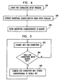
- Fig. 4 is a simplified flowchart illustration of a preferred implementation of step 200 of Fig. 3.
- the method of Fig. 4 preferably comprises the following steps:
- Fig. 5 is a simplified flowchart illustration of a preferred implementation of a portion of step 230 of Fig. 3, in which grouping or summing is performed.
- the method of Fig. 5 preferably includes the following steps:
- a check is preferably made to see whether the stored characteristics of the ATM connection match the search key (step 280). If not processing continues with step 270.
- step 280 If the stored characteristics of the ATM connection did match the search key in step 280, the stored ATM connection is preferably combined, as described above, with stored data from other ATM connections corresponding to the search key. Processing then continues with step 270.
- the first phase of AMON provides monitoring capabilities for the following ATM forum standards:
- the AMON Host and Matrix applications are heavy users of memory. As a result, the amount of addresses and address pairs which are stored and supported by each application are a function of the amount of memory which is installed on the switch: Memory on switch ATM addresses supported in Host statistics ATM address pairs supported in Host Matrix 8M 400 1,000 16M and higher 4,000 10,000
- the AMON probe is a part of the ATM switch's software, running in parallel to other functions performed by the CPU.
- the probe collects ATM level statistics. These are collected by analyzing various properties of the VCs during signaling setup (using information available in the setup process), and correlating this data with the per-VC counters collected by the switch's HW. This enables the CPU to collect RMON-like statistics at the ATM level.
- ATM level statistics are collected by analyzing properties of the VCs during signaling setup, and correlating these properties with the cell counters provided per VC by the switch's HW.
- the ATM level functions provided by the AMON probe are:
- ATM Switch statistics and ATM Port statistics are collected by the probe at all times.
- the other 3 groups - ATM Host, ATM Host Top N, and ATM Matrix statistics are collected by the probe upon request from the management station.
- the probe is capable of collecting all groups simultaneously.
- the switch's signaling entity typically transfers to the AMON entity for all connections passing through the switch, data which typically but not necessarily includes the following:
- Point-to-Multipoint connections maintained by the connection manager typically have one of 3 types:
- Fig. 6 illustrates the typical connections which are reported in a switch of a preferred embodiment of the present invention.
- connection types which are typically reported to AMON are:
- MIB definitions disclosed herein provide examples of the information that can be collected by AMON. These examples are not intended to be limiting and in particular additional other information can be collected.
- the MIB items represent preferred embodiments of the present invention and are not essential features of the invention.
- the AMON probe collects statistics related to the switch as a global entity.
- Switch statistics which are collected by summing the relevant VC counters of all VCs active on the switch. Statistics are typically collected by the probe at all times.
- the following table defines the counters which are supported at the switch level MIB item Notes 1.
- DropCellEvents 2.
- DropFrameEvents 0
- TotalCells 4.
- BadHecCells 5.
- UbrCells 7.
- AbrCells 8.
- NonRtVbrCells 9.
- RtVbrCells Will be 0 in V1.2 of the C740.
- CbrCells 11. PnniCells 12.
- SignalingCells 13.
- LaneCells 14.
- Lane802Dot3DataDirectCells 15. Lane802Dot3MulticastCells 16. Lane802Dot5DataDirectCells 17. Lane802Dot5MulticastCells 18. LaneConfigControlCells 19. TotalBwAllocated 20. AbrBwAllocated 21. 22. NonRtVbrBwAllocated RtVbrBwAllocated 23. CbrBwAllocated
- the AMON probe collects statistics related to the physical ports of the ATM switch. Statistics are collected at all times for all ports in the PortTable. When a port is added to the switch or removed from it in run-time, the table is updated accordingly to reflect the correct status of the switch. Port statistics are collected by summing the relevant VC counters of all VCs active on the port. The counters which are supported for each port are: MIB item Notes 1. PortInCells 2. PortOutCells 3. PortInBadHecCells 4. PortInUbrCells 5. PortInAbrCells 6. PortInNonRtVbrCells 7. PortInRtVbrCells 8. PortInCbrCells 9. PortInPointToPointCells 10.
- PortInPointToMultipointCells 11. PortInLane8O2Dot3DataDirectCelis 12. PortInLane802Dot3MulticastCells 13. PortInLane802Dot5DataDirectCells 14. PortInLane802Dot5MulticastCells 15. PortInLaneConfigControlCells 16. PortActiveVcs 17. PortUbrVcs 18. PortAbrVcs Will be 0 if ABR is not supported 19. PortNonRtVbrVcs 20. PortRtVbrVcs Will be 0 in V1.3 of the C740. 21. PortCbrVcs 22. PortPointToPointVcs 23. PortPointToMultipointVcs 24.
- PortLane802Dot3DataDirectVcs 25. PortLane802Dot3MulticastVcs 26. PortLane802Dot5DataDirectVcs 27. PortLane802Dot5MulticastVcs 28. PortLaneConfigControlVcs
- ATM Host Statistics are provided by the RMON Host group, and preferably by additional non-RMON mibs. Statistics regarding an ATM host are computed as the sum of the traffic on all VCCs connected to this host. Collection of statistics are activated by the RMON MIB's hostControlTable, both for the RMON MIB counters and for the non-RMON table of the non-RMON mibs.
- the probe typically supports the following RMON MIB tables:
- the actions performed by the probe preferably include some or all of the following actions:
- the probe supports the non-RMON atmHostTimeTable. This table is indexed by the same indices as the RMON hostTimeTable, and is created by the RMON hostControlTable.
- the counters which are typically collected are: MIB item Notes 1. InCells 2. OutCells 3. OutUbrCells 4. OutAbrCells 5. OutNonRtVbrCells 6. OutRtVbrCells Will be 0 in V1.3 of the C740. 7. OutCbrCells 8. OutPnniCells 9. OutSignalingCells 10. InLaneCells 11. OutLaneCells 12. OutLane802Dot3DataDirectCells 13. OutLane802Dot3MulticastCells 14.
- ATM Host Top N provides an agent based sorting mechanism on the data found for ATM hosts. This is done using the standard RMON MIB and non-RMON additions to it.
- the AMON probe typically supports all tables required by the Host Top N mechanism, i.e.:
- Host Top N statistics is typically triggered when one of the following happens:
- the following relationship between the host table and the hostTopN table can typically be implemented: Change to Host Table Result in hostTopN control table Result in hostTopN table - valid -> invalid. - timeRemaining -> 0. - does not change. - valid -> underCreation. - status: does not change. - underCreation -> invalid. - No change. - No change. Change to HostTopN control Table Result in hostTopN table - valid -> underCreation. - Relevant entries deleted. - any status -> invalid. - Relevant entries deleted.
- the ATM Host Matrix is provided by the RMON Matrix group.
- the probe supports all ables defined in the RMON MIB's matrix group, i.e.:
- the probe supports the non-RMON amonMatrix SDTable.
- MIB item Method of computation Notes matnxPkts amonMatrixTotalCells matrixOctets matrixPkts*53 matrixErrors Always 0 The following implementation specific issues are can typically be utilized:
- the probe When an ATM Matrix collection session begins, the probe performs the following actions:
- the probe supports the non-RMON atmMatrixSDTable. This table is indexed by the same indices as the RMON MatrixSDTable, and is created by the RMON MatrixControlTable.
- the counters which are typically collected are: MIB item Notes 1. Total Cells 2. UbrCells 3. AbrCells 4. NonRtVbrCells 5. RtVbrCells Will be 0 in V1.3 of the C740. 6. CbrCells 7. PnniCells 8. SignalingCells 9. LaneCells
- the agent updates the relevant MIB tables when a new entity is discovered - i.e., a new host, session, port or VC. This typically happens in two cases:
- the entries pertaining to that VC are typically treated as follows:
- the port tables are updated to reflect the status of the switch.
- This section describes an interface suitable for the Madge (NAME OF..) Collage 740 ATM switch and commercially available from Madge Networks Ltd., Atidim Technology Park, Building 3, Tel-Aviv 61131, Israel, and is typically different for other commercially available switches.
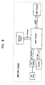
- the AMON application interfaces with a number of switch functions.
- a simplified block diagram of a preferred interface between AMON and the switch is illustrated in Fig. 8.
- MIB MIB
- the software components of the present invention may, if desired, be implemented in ROM (read-only memory) form.
- the software components may, generally, be implemented in hardware, if desired, using conventional techniques.
Landscapes
- Engineering & Computer Science (AREA)
- Computer Networks & Wireless Communication (AREA)
- Signal Processing (AREA)
- Environmental & Geological Engineering (AREA)
- Data Exchanges In Wide-Area Networks (AREA)
Claims (22)
- Verfahren zur Analyse der Leistung eines ATM-Netzwerks, wobei das Netzwerk eine erste Vielzahl von Stationen umfasst, die über eine zweite Vielzahl von ATM-Verbindungen miteinander verbunden sind, wobei das Verfahren umfasst:Abhören wenigstens eines ATM-Verbindungsmerkmals von wenigstens zwei der zweiten Vielzahl von ATM-Verbindungen und Speichern des wenigstens einen ATM-Verbindungsmerkmals in einem ATM-Verbindungsmerkmalsspeicher;Überwachen wenigstens eines Operationsparameters der wenigstens zwei der zweiten Vielzahl von ATM-Verbindungen und Speichern der Operationsparameter in dem ATM-Verbindungsmerkmalsspeicher;für wenigstens eine ATM-Verbindungsuntermenge, die wenigstens zwei der zweiten Vielzahl von ATM-Verbindungen umfasst, die mit einem Abfrageschlüssel übereinstimmen, wobei der Abfrageschlüssel eine Kombination von wenigstens einem der ATM-Verbindungsmerkmale umfasst und unter Verwendung des Abfrageschlüssels die Operationsparameter für jede ATM-Verbindung in der ATM-Verbindungsuntermenge aus dem Speicher abfrägt und Kombinieren der Operationsparameter in einen charakterisierenden Wert der Untermengenoperation, der die Operation der Untermenge charakterisiert; undErzeugen einer Ausgabedarstellung des charakterisierenden Werts der Untermengenoperation.
- Verfahren nach Anspruch 1, wobei die Operationsparameter eine Menge an Datenverkehr sind, die über wenigstens zwei der zweiten Vielzahl von ATM-Verbindungen läuft und wobei der charakterisierende Wert der Untermengenoperation eine Gesamtmenge an Datenverkehr darstellt, die über die ATM-Verbindungsuntermenge gelaufen ist.
- Verfahren nach Anspruch 2, wobei das wenigstens eine ATM-Verbindungsmerkmal eine Identifikation von wenigstens einer der Stationen aufweist, die über eine einzelne ATM-Verbindung miteinander verbunden sind.
- Verfahren nach Anspruch 2, wobei wenigstens eine der ATM-Verbindungen eine LAN-Emulation ATM-Verbindung aufweist und das wenigstens eine ATM-Verbindungsmerkmal eine Protokoll ID für die LAN-Emulation aufweist.
- Verfahren nach Anspruch 2, wobei das wenigstens eine ATM-Verbindungsmerkmal einen Datenverkehrsqualitätsservicetyp einer ATM-Verbindung aufweist.
- Verfahren nach Anspruch 2, wobei das wenigstens eine ATM-Verbindungsmerkmal eine Funktion aufweist, die eine ATM-Verbindung erfüllt.
- Verfahren nach Anspruch 1, wobei der wenigstens eine Operationsparameter eine Charakterisierung von Fehlern, die über die ATM-Verbindung übermittelt wurden, aufweist.
- Verfahren nach Anspruch 1 oder 2, wobei der Schritt der Erzeugung einer Ausgabedarstellung das Erzeugen einer Computeranzeige aufweist.
- Verfahren nach Anspruch 1 oder 2, wobei der Abfrageschlüssel eine Boolsche Kombination einer Vielzahl von den ATM-Verbindungsmerkmalen aufweist.
- Verfahren nach Anspruch 2, wobei der Schritt der Überwachung der Datenverkehrsmenge das Überwachen des Datenverkehrs aufweist, der in eine Richtung über die wenigsten zwei der zweiten Vielzahl von ATM-Verbindungen läuft.
- Verfahren nach Anspruch 5, wobei der Datenverkehrsservicetyp wenigstens eine der folgenden aufweist: CBR, RT-VBR, NRT-VBR, ABR.
- Verfahren nach Anspruch 6, wobei die Funktion, die die ATM-Verbindung erfüllt, wenigstens eine der folgenden aufweist: PNNI, Signalisierung, LAN-Emulation.
- Verfahren nach Anspruch 2, wobei der Schritt der Überwachung der Datenverkehrsmenge das getrennte Überwachen der Datenverkehrsmenge aufweist, die in jede der zwei Richtungen über die wenigstens zwei der zweiten Vielzahl von ATM-Verbindungen läuft.
- Verfahren nach Anspruch 2, wobei die wenigstens zwei der zweiten Vielzahl von ATM-Verbindungen eine Vielzahl von Unterverbindungen aufweist, und
wobei der Schritt der Überwachung der Datenverkehrsmenge das getrennte Überwachen der Datenverkehrsmenge aufweist, die über jede Unterverbindung von wenigstens zwei der zweiten Vielzahl von ATM-Verbindungen läuft. - Verfahren nach Anspruch 14, wobei die ATM-Verbindungsmerkmale einen Unterverbindungs-Identifizierer aufweisen.
- Verfahren nach Anspruch 15, wobei der Unterverbindungs-Identifizierer eine Richtung aufweist, die der Unterverbindung zugeordnet ist.
- Verfahren nach Anspruch 1, wobei der Schritt der Erzeugung einer Ausgabedarstellung das Erzeugen eines Alarms aufweist, wenn ein Schwellenwert erreicht ist.
- Verfahren nach Anspruch 2, wobei der Schritt des Abhörens während des Aufbaus der zweiten Vielzahl von ATM-Verbindungen durchgeführt wird.
- ATM-Operationsparameter-Analysevorrichtung zur Verwendung in Verbindung mit einem ATM-Netzwerk, wobei das ATM-Netzwerk eine erste Vielzahl von Netzwerkelementen aufweist, welche eine Vielzahl von Stationen (145, 150, 155) und wenigstens einen Verteiler (100, 135) umfasst, sowie eine zweite Vielzahl von ATM-Verbindungen (125, 130), wobei die erste Vielzahl von Stationen über die zweite Vielzahl von ATM-Verbindungen, die wenigstens einem Verteiler zugeordnet sind, miteinander verbunden ist, wobei die Operationsparameter-Analysevorrichtung aufweist:einen ATM-Verbindungsmerkmalsspeicher (175);ein ATM-Verbindungsmerkmals-Überwachungsgerät (168), das wirksam ist, um wenigstens ein ATM-Verbindungsmerkmal von wenigstens zwei der zweiten Vielzahl von ATM-Verbindungen abzuhören und das wenigstens eine ATM-Verbindungsmerkmal in dem ATM-Verbindungsmerkmalspeicher zu speichern;ein ATM-Verbindungsoperationsparameter-Überwachungsgerät (170), das wirksam ist, um wenigstens einen Operationsparameter von wenigstens zwei der zweiten Vielzahl von ATM-Verbindungen zu überwachen und die Operationsparameter in dem ATM-Verbindungsspeicher zu speichern;einen ATM-Verbindungsoperationsparameter-Analysierer (180), der wirksam ist, um für wenigstens eine ATM-Verbindungsuntermenge, die die wenigstens zwei der zweiten Vielzahl von ATM-Verbindungen umfasst, welche einen Wiederauffindschlüssel erfüllt, die Operationsparameter für jede ATM-Verbindung in der ATM-Verbindungsuntermenge aus dem Speicher unter Verwendung des Abfrageschlüssels wieder aufzufinden, wobei der Abfrageschlüssel eine Kombination von wenigstens einem der ATM-Verbindungsmerkmale umfasst, und um die Operationsparameter in einen charakterisierenden Wert der Untermengenoperation, der die Operation der Untermenge charakterisiert, zu kombinieren; undeine Ausgabevorrichtung (185), die wirksam ist, eine Ausgabedarstellung des charakterisierenden Werts der Untermengenoperation zu erzeugen.
- Vorrichtung nach Anspruch 19, wobei das wenigstens eine Netzwerkelement, das die Operationsparameter-Analysevorrichtung umfasst, wenigstens eine Station aufweist.
- Vorrichtung nach Anspruch 19 oder 20, wobei das wenigstens eine Netzwerkelement, das die Operationsparameter-Analysevorrichtung umfasst, wenigstens einen Verteiler aufweist.
- Vorrichtung nach Anspruch 19, wobei das wenigstens eine Netzwerkelement, das die Operationsparameter-Analysevorrichtung umfasst, eine Vielzahl von Netzwerkelementen aufweist, wobei jedes die Operationsparameter-Analysevorrichtung umfasst und auch eine Ausgabewertverarbeitungseinheit aufweist, die wirksam ist, eine fünfte Vielzahl von charakterisierenden Werten der Untermengenoperation von einer fünften Vielzahl von ATM-Verbindungsoperationsparameter-Analysierern zu erhalten und die fünfte Vielzahl von charakterisierenden Werten der Untermengenoperation in einen einzelnen Wert zu kombinieren.
Applications Claiming Priority (3)
| Application Number | Priority Date | Filing Date | Title |
|---|---|---|---|
| IL11736696A IL117366A (en) | 1996-03-04 | 1996-03-04 | System for parameter analysis in asynchronous transfer mode (atm) networks |
| IL11736696 | 1996-03-04 | ||
| PCT/IL1997/000079 WO1997035405A1 (en) | 1996-03-04 | 1997-03-03 | System for parameter analysis and traffic monitoring in asynchronous transfer mode (atm) networks |
Publications (3)
| Publication Number | Publication Date |
|---|---|
| EP0958679A1 EP0958679A1 (de) | 1999-11-24 |
| EP0958679A4 EP0958679A4 (de) | 2005-06-15 |
| EP0958679B1 true EP0958679B1 (de) | 2006-12-27 |
Family
ID=11068626
Family Applications (1)
| Application Number | Title | Priority Date | Filing Date |
|---|---|---|---|
| EP97903578A Expired - Lifetime EP0958679B1 (de) | 1996-03-04 | 1997-03-03 | System zur parameteranalyse und verkehrsüberwachung in atm-netzen |
Country Status (7)
| Country | Link |
|---|---|
| US (1) | US6021117A (de) |
| EP (1) | EP0958679B1 (de) |
| JP (1) | JP2001503927A (de) |
| AU (1) | AU1809897A (de) |
| DE (1) | DE69737150T2 (de) |
| IL (1) | IL117366A (de) |
| WO (1) | WO1997035405A1 (de) |
Families Citing this family (22)
| Publication number | Priority date | Publication date | Assignee | Title |
|---|---|---|---|---|
| US6216169B1 (en) * | 1997-10-06 | 2001-04-10 | Concord Communications Incorporated | Generating reports using distributed workstations |
| JP3450177B2 (ja) * | 1998-03-20 | 2003-09-22 | 富士通株式会社 | ネットワーク監視システム及び被監視制御装置 |
| FI110987B (fi) | 1998-03-31 | 2003-04-30 | Nokia Corp | Menetelmä tiedonsiirtovirtausten kytkemiseksi |
| US6289017B1 (en) * | 1998-05-29 | 2001-09-11 | 3Com Corporation | Method of providing redundancy and load sharing among multiple LECs in an asynchronous mode network |
| US6097699A (en) * | 1998-06-05 | 2000-08-01 | Gte Laboratories Incorporated | Method and system for monitoring broadband quality of services |
| US6411604B1 (en) | 1998-06-05 | 2002-06-25 | Inet Technologies, Inc. | System and method for correlating transaction messages in a communications network |
| US6529594B1 (en) | 1998-06-05 | 2003-03-04 | Inet Technologies, Inc. | System and method for generating quality of service statistics for an international communications network |
| GB9826675D0 (en) * | 1998-12-04 | 1999-01-27 | Hewlett Packard Co | Monitoring links in ATM networks |
| US7382736B2 (en) | 1999-01-12 | 2008-06-03 | Mcdata Corporation | Method for scoring queued frames for selective transmission through a switch |
| IL130415A (en) * | 1999-06-10 | 2003-07-31 | Eci Telecom Ltd | Method of defining threshold crossing alert profiles for network element performance monitoring |
| SE514884C2 (sv) * | 2000-04-26 | 2001-05-14 | Telia Ab | Apparat och metod för mätning och bearbetning av information i ett paketorienterat kommunikationssystem |
| US6718384B2 (en) * | 2000-08-09 | 2004-04-06 | Fujitsu Network Communications, Inc. | System and method for monitoring and maintaining a communication network |
| AU2001285068A1 (en) * | 2000-08-17 | 2002-02-25 | Trendium, Inc. | Methods, systems, and computer program products for managing a service provided by a network |
| CA2365430A1 (en) * | 2001-12-19 | 2003-06-19 | Alcatel Canada Inc. | System and method for collecting statistics for a communication network |
| US7844697B1 (en) * | 2002-01-25 | 2010-11-30 | Juniper Networks, Inc. | Measuring network traffic based on predicted amount of padding |
| US8479057B2 (en) * | 2002-11-04 | 2013-07-02 | Riverbed Technology, Inc. | Aggregator for connection based anomaly detection |
| US8504879B2 (en) * | 2002-11-04 | 2013-08-06 | Riverbed Technology, Inc. | Connection based anomaly detection |
| EP1478126A1 (de) * | 2003-05-16 | 2004-11-17 | Siemens Aktiengesellschaft | Echtzeitüberwachung des Messdaten für Telekommunikationssysteme |
| US7460484B2 (en) * | 2004-09-07 | 2008-12-02 | Alcatel Lucent | Lawful intercept of traffic connections |
| US7464161B2 (en) * | 2005-06-06 | 2008-12-09 | International Business Machines Corporation | Enabling and disabling byte code inserted probes based on transaction monitoring tokens |
| EP2879339A1 (de) * | 2013-11-27 | 2015-06-03 | Thomson Licensing | Verfahren zur Verteilung der verfügbaren Bandbreite eines Netzwerks zwischen laufenden Datenverkehrssitzungen, die von den Vorrichtungen des Netzwerks ausgeführt werden, zugehörige Vorrichtung |
| JP2017028426A (ja) * | 2015-07-21 | 2017-02-02 | Necプラットフォームズ株式会社 | 通信量集計装置、通信量集計方法、中継装置および中継方法 |
Family Cites Families (9)
| Publication number | Priority date | Publication date | Assignee | Title |
|---|---|---|---|---|
| CA2038646C (en) * | 1990-03-20 | 1995-02-07 | Katsumi Oomuro | Atm communication system with optimal traffic control by changing the allocated bandwidth |
| JPH04100342A (ja) * | 1990-08-20 | 1992-04-02 | Toshiba Corp | トラヒック制御方式 |
| FR2711466B1 (fr) * | 1993-10-20 | 1996-01-26 | Tremel Jean Yves | Appareil de test de réseau de télécommunication de type ATM et de mesure de performance de connexion ATM. |
| US5530695A (en) * | 1993-12-15 | 1996-06-25 | Nec Usa, Inc. | UPC-based traffic control framework for ATM networks |
| JPH0897820A (ja) * | 1994-09-29 | 1996-04-12 | Hitachi Ltd | Upc回路と性能監視セル処理回路 |
| US5636345A (en) * | 1995-03-30 | 1997-06-03 | Bay Networks, Inc. | Method and apparatus for detecting and preventing broadcast storms on an emulated local area network |
| US5638371A (en) * | 1995-06-27 | 1997-06-10 | Nec Usa, Inc. | Multiservices medium access control protocol for wireless ATM system |
| US5764626A (en) * | 1995-11-17 | 1998-06-09 | Telecommunications Techniques Corporation | Rate-matched cell identification and modification, replacement, or insertion for test and measurement of ATM network virtual connections |
| US5751698A (en) * | 1996-03-15 | 1998-05-12 | Network General Technology Corporation | System and method for automatically identifying and analyzing active channels in an ATM network |
-
1996
- 1996-03-04 IL IL11736696A patent/IL117366A/xx not_active IP Right Cessation
-
1997
- 1997-03-03 DE DE69737150T patent/DE69737150T2/de not_active Expired - Fee Related
- 1997-03-03 AU AU18098/97A patent/AU1809897A/en not_active Abandoned
- 1997-03-03 US US08/810,194 patent/US6021117A/en not_active Expired - Lifetime
- 1997-03-03 EP EP97903578A patent/EP0958679B1/de not_active Expired - Lifetime
- 1997-03-03 JP JP53331197A patent/JP2001503927A/ja active Pending
- 1997-03-03 WO PCT/IL1997/000079 patent/WO1997035405A1/en not_active Ceased
Also Published As
| Publication number | Publication date |
|---|---|
| EP0958679A1 (de) | 1999-11-24 |
| WO1997035405A1 (en) | 1997-09-25 |
| IL117366A0 (en) | 1996-07-23 |
| DE69737150D1 (de) | 2007-02-08 |
| AU1809897A (en) | 1997-10-10 |
| JP2001503927A (ja) | 2001-03-21 |
| EP0958679A4 (de) | 2005-06-15 |
| DE69737150T2 (de) | 2007-10-04 |
| IL117366A (en) | 1999-05-09 |
| US6021117A (en) | 2000-02-01 |
Similar Documents
| Publication | Publication Date | Title |
|---|---|---|
| US6021117A (en) | System for parameter analysis and traffic monitoring in asynchronous transfer mode (ATM) networks | |
| DE69511679T2 (de) | Transparenter verbinder von lokalen netzen über ein atm-netz | |
| US6205148B1 (en) | Apparatus and a method for selecting an access router's protocol of a plurality of the protocols for transferring a packet in a communication system | |
| US7120689B2 (en) | Receiving network metrics data from disparate devices and displaying in a host format | |
| EP0613270B1 (de) | Netzanalysenverfahren | |
| US6421319B1 (en) | Network traffic monitoring system | |
| US7864773B2 (en) | Virtual circuit auto-configuration for customer premises equipment | |
| Ahmed et al. | Definitions of managed objects for ATM management version 8.0 using SMIv2 | |
| US6608817B1 (en) | Method and apparatus for connection-oriented multiplexing and switching network analysis, management, and troubleshooting | |
| US7706293B2 (en) | Performance management system, apparatus and method between residential gateway and broadband remote access server | |
| EP1190535B1 (de) | Topologiebestimmung in atm-netzen | |
| Tesink | Definitions of Managed Objects for ATM Management | |
| US7860023B2 (en) | Layer 2 network rule-based non-intrusive testing verification methodology | |
| Brown et al. | Management Information Base for Frame Relay DTEs Using SMIv2 | |
| JPH09214509A (ja) | ルーティング方式 | |
| US6580693B1 (en) | Methods and apparatus for detecting leaks in ATM networks | |
| US6977936B1 (en) | Service detail records for layered communications protocols | |
| Ly et al. | Definitions of Supplemental Managed Objects for ATM Management | |
| Brown et al. | RFC2115: Management Information Base for Frame Relay DTEs Using SMIv2 | |
| Newman et al. | RFC1987: Ipsilon's General Switch Management Protocol Specification Version 1.1 | |
| Rehbehn et al. | Definitions of Managed Objects for Frame Relay Service | |
| Choi et al. | OAM MIB: an end-to-end performance management solution for ATM | |
| Kanamaru et al. | A simple packet aggregation technique for fault detection | |
| Ly et al. | Definitions of Supplemental Managed Objects for ATM Interface | |
| Piscitello et al. | Network management capabilities for switched multi-megabit data service |
Legal Events
| Date | Code | Title | Description |
|---|---|---|---|
| PUAI | Public reference made under article 153(3) epc to a published international application that has entered the european phase |
Free format text: ORIGINAL CODE: 0009012 |
|
| 17P | Request for examination filed |
Effective date: 19981218 |
|
| AK | Designated contracting states |
Kind code of ref document: A1 Designated state(s): DE FR GB |
|
| A4 | Supplementary search report drawn up and despatched |
Effective date: 20050504 |
|
| RIC1 | Information provided on ipc code assigned before grant |
Ipc: 7H 04L 12/56 A |
|
| GRAP | Despatch of communication of intention to grant a patent |
Free format text: ORIGINAL CODE: EPIDOSNIGR1 |
|
| RTI1 | Title (correction) |
Free format text: SYSTEM FOR PARAMETER ANALYSIS AND TRAFFIC MONITORING IN ASYNCHRONOUS TRANSFER MODE NETWORKS |
|
| GRAS | Grant fee paid |
Free format text: ORIGINAL CODE: EPIDOSNIGR3 |
|
| GRAA | (expected) grant |
Free format text: ORIGINAL CODE: 0009210 |
|
| AK | Designated contracting states |
Kind code of ref document: B1 Designated state(s): DE FR GB |
|
| REG | Reference to a national code |
Ref country code: GB Ref legal event code: FG4D |
|
| REF | Corresponds to: |
Ref document number: 69737150 Country of ref document: DE Date of ref document: 20070208 Kind code of ref document: P |
|
| ET | Fr: translation filed | ||
| PLBE | No opposition filed within time limit |
Free format text: ORIGINAL CODE: 0009261 |
|
| STAA | Information on the status of an ep patent application or granted ep patent |
Free format text: STATUS: NO OPPOSITION FILED WITHIN TIME LIMIT |
|
| 26N | No opposition filed |
Effective date: 20070928 |
|
| PGFP | Annual fee paid to national office [announced via postgrant information from national office to epo] |
Ref country code: DE Payment date: 20090226 Year of fee payment: 13 |
|
| PGFP | Annual fee paid to national office [announced via postgrant information from national office to epo] |
Ref country code: FR Payment date: 20090316 Year of fee payment: 13 |
|
| REG | Reference to a national code |
Ref country code: FR Ref legal event code: ST Effective date: 20101130 |
|
| PG25 | Lapsed in a contracting state [announced via postgrant information from national office to epo] |
Ref country code: FR Free format text: LAPSE BECAUSE OF NON-PAYMENT OF DUE FEES Effective date: 20100331 |
|
| PG25 | Lapsed in a contracting state [announced via postgrant information from national office to epo] |
Ref country code: DE Free format text: LAPSE BECAUSE OF NON-PAYMENT OF DUE FEES Effective date: 20101001 |
|
| PGFP | Annual fee paid to national office [announced via postgrant information from national office to epo] |
Ref country code: GB Payment date: 20130228 Year of fee payment: 17 |
|
| GBPC | Gb: european patent ceased through non-payment of renewal fee |
Effective date: 20140303 |
|
| PG25 | Lapsed in a contracting state [announced via postgrant information from national office to epo] |
Ref country code: GB Free format text: LAPSE BECAUSE OF NON-PAYMENT OF DUE FEES Effective date: 20140303 |