EP0958502B1 - Magnetischer messfühler - Google Patents
Magnetischer messfühler Download PDFInfo
- Publication number
- EP0958502B1 EP0958502B1 EP98910585A EP98910585A EP0958502B1 EP 0958502 B1 EP0958502 B1 EP 0958502B1 EP 98910585 A EP98910585 A EP 98910585A EP 98910585 A EP98910585 A EP 98910585A EP 0958502 B1 EP0958502 B1 EP 0958502B1
- Authority
- EP
- European Patent Office
- Prior art keywords
- magnetic
- hydrogen
- magnetic field
- sensor
- intermediate layers
- Prior art date
- Legal status (The legal status is an assumption and is not a legal conclusion. Google has not performed a legal analysis and makes no representation as to the accuracy of the status listed.)
- Expired - Lifetime
Links
Images

Classifications
-
- B—PERFORMING OPERATIONS; TRANSPORTING
- B82—NANOTECHNOLOGY
- B82Y—SPECIFIC USES OR APPLICATIONS OF NANOSTRUCTURES; MEASUREMENT OR ANALYSIS OF NANOSTRUCTURES; MANUFACTURE OR TREATMENT OF NANOSTRUCTURES
- B82Y25/00—Nanomagnetism, e.g. magnetoimpedance, anisotropic magnetoresistance, giant magnetoresistance or tunneling magnetoresistance
-
- G—PHYSICS
- G01—MEASURING; TESTING
- G01R—MEASURING ELECTRIC VARIABLES; MEASURING MAGNETIC VARIABLES
- G01R33/00—Arrangements or instruments for measuring magnetic variables
- G01R33/02—Measuring direction or magnitude of magnetic fields or magnetic flux
- G01R33/06—Measuring direction or magnitude of magnetic fields or magnetic flux using galvano-magnetic devices
- G01R33/09—Magnetoresistive devices
- G01R33/093—Magnetoresistive devices using multilayer structures, e.g. giant magnetoresistance sensors
-
- G—PHYSICS
- G11—INFORMATION STORAGE
- G11C—STATIC STORES
- G11C11/00—Digital stores characterised by the use of particular electric or magnetic storage elements; Storage elements therefor
- G11C11/02—Digital stores characterised by the use of particular electric or magnetic storage elements; Storage elements therefor using magnetic elements
- G11C11/14—Digital stores characterised by the use of particular electric or magnetic storage elements; Storage elements therefor using magnetic elements using thin-film elements
- G11C11/15—Digital stores characterised by the use of particular electric or magnetic storage elements; Storage elements therefor using magnetic elements using thin-film elements using multiple magnetic layers
-
- H—ELECTRICITY
- H10—SEMICONDUCTOR DEVICES; ELECTRIC SOLID-STATE DEVICES NOT OTHERWISE PROVIDED FOR
- H10N—ELECTRIC SOLID-STATE DEVICES NOT OTHERWISE PROVIDED FOR
- H10N50/00—Galvanomagnetic devices
- H10N50/80—Constructional details
- H10N50/85—Materials of the active region
Definitions
- the invention relates to a magnetic sensor with hydrogen loading defines changeable internal - the difference of electrical Characterizing resistance with applied and switched off magnetic field - Magnetic resistance, consisting of a multi-layer package each alternating ferromagnetic layers and hydrogen affine non-magnetic intermediate layers on a substrate, the layers and the intermediate layers magnetically by the exchange of spin polarized Electrons are coupled, and a top layer of Pd for hydrogen activation.
- the coupling strength between the ferromagnetic layers can, for example a damped oscillation as a function of the interlayer thickness between the ferromagnetic and the antiferromagnetic state To run.
- the choice of the interlayer thickness means that Magnetic resistance of a single multi-layer package defined. A change, for example in the sense of optimization for the respective The magnetic sensor is used after its manufacture not possible anymore.
- the layer thicknesses used for intermediate layers made of Nb are below 1.3 nm and above 2.3 nm. All layer thicknesses per layer package are constant.
- the internal magnetic resistance in direct connection with the possible hydrogen loading, can only be determined during the production of the intermediate layers by the choice of their layer thicknesses and can therefore only be changed in a defined manner from layer package to layer package. After the layer package has been produced, it is not possible to change the internal magnetic resistance in the sense of fine tuning. There is no confirmation of the theory about the possibility of a continuous and reversible influence on the magnetic resistance for its continuous and reversible change by means of a corresponding hydrogen loading.
- Antiferromagnetically ordered layers have a magnetic resistance that is particularly suitable for measuring magnetic fields.
- article III Phys. BI. 51 (1995) No. 11, 1077-1081, P.Grünberg, "Giant magnetoresistance in magnetic layer structures" describes the use of magnetic layer structures for magnetic sensors with a variation in the intermediate layer thickness.
- the magnetic measuring sensors known from attachment III in which the multi-layer package is constructed in the manner already described from a plurality of ferromagnetic layers which are magnetically coupled to one another via magnetic non-magnetic intermediate layers for the basic setting of the magnetic resistance, serve exclusively to determine changes in the magnetic resistance. This makes them suitable for use as field sensors. They can serve as magnetic heads for reading out the information on magnetic information carriers, others for detecting position or speed if the objects to be measured can generate a magnetic field. Precise reading can only be achieved by optimizing the change in resistance in the magnetic field. In the case of such known magnetic measuring sensors, this optimization setting takes place via the choice of the layer thicknesses of the non-magnetic intermediate layers.
- this measure limits the use of the magnetic measuring sensors exclusively to applications for field sensors for determining the magnetic field strength as the only physical measurement variable, since the magnetic resistance of such magnetic measuring sensors can only be influenced by external external magnetic fields.
- the technical problem on which the invention is based consists in designing a magnetic measuring sensor of the type described in the introduction in such a way that after its manufacture, its internal magnetic resistance can be changed for application-specific optimization. Furthermore, the basic structure of the multi-layer packages should differ as little as possible for different purposes.
- the solution according to the invention for this can be found in claim 1. It has surprisingly been found that the changes in the internal magnetic resistance due to hydrogen loading are much more effective for the specified layer thickness than for other layer thicknesses.
- the magnetic resistance can thus at any time after completion of the shift package continuous and reversible within wide limits (up to three times the Initial value) on the concentration of hydrogen in the intermediate layers to be changed. This is e.g. for the application area of Magnetic field sensors with different sensitivities and / or basic settings of crucial importance. Changes, in particular Magnetic sensitivity deterioration due to aging Layers can be compensated for by renewed hydrogen loading become. There are also overcorrections due to the reversibility of the hydrogen loading by treating the layer package with reduced Hydrogen partial pressure can be compensated.
- the optimization takes place via the possibility of continuous and reversible influencing of the intermediate layers by the Hydrogen loading or unloading.
- the intermediate layers consist of a highly hydrogen-affine material. This can be Nb or an alloy of Cr with one of the strongly hydrogen-affine elements V, Nb or Ta act. Alloys of this type have a Cr component compared to Nb via a fundamentally larger magnetic resistance, which further improves the sensitivity of the magnetic sensor can be.
- an activator catalyst
- the top layer also protects the layer package against oxidation.
- the layer thickness of the intermediate layers is the layer thickness of the intermediate layers.
- Nb with a layer thickness between 1.3 nm and 1.6 nm can be an effective one Change in the magnetic coupling between the ferromagnetic and the antiferromagnetic state due to the hydrogen loading be effected.
- the layer thickness in a larger range between 0.8 nm and 2.3 nm are the electronic properties related to the antiferromagnetic Coupling comparable between Nb intermediate layers and chrome alloyed Interlayers.
- the subsequent fine tuning plays a very precise Adherence to the layer thickness is not essential.
- the manufacturing tolerances are therefore relatively large in the range (for example in 0.3 nm steps), so that the manufacture of the individual layers is simplified and the Reject rate can be reduced.
- the effect of tolerances of ferromagnetic Layers on the magnetic resistance can be subsequently adjusted by fine tuning just be balanced.
- An advantageous embodiment of the layer structure of the invention magnetic sensor is that between a substrate made of Si or GaAs and a multi-layer package with ferromagnetic layers Fe, Co, Ni, or their alloys, a Cr buffer layer is provided.
- This Cr buffer layer acts as a diffusion barrier and thus prevents one Mixing of substrate material with material from the multi-layer package. This will influence the magnetic properties of the Multi-layer packages excluded by substrate material.
- the buffer layer can have a thickness in the range of 5 nm.
- the magnetic measuring sensor according to the invention can both by external magnetic fields as well as by hydrogen supply in his Magnet resistance can be changed. With his help, therefore, two physically completely different measurands (magnetic field strength and Hydrogen concentration) can be determined. These measurands can by a 4-pole resistance measuring arrangement assigned to the measuring sensor is determined become. All of these metrics are determined by determining them influenced electrical resistance of the sensor. in this connection becomes an output voltage depending on a constant one Measuring electronics specifiable current in this 4-pole resistance measuring arrangement measured. For this arrangement, the constant current is compared to two lying corner points of the multi-layer package and the variable voltage tapped at the other two corner points. The Measurement signal is for an exact calculation, for example in a Measurement processing computer system, the variable electrical Resistance sufficiently large and accurate.
- the hydrogen loading of the intermediate layers can take place reversibly, i.e. stored hydrogen can also come from the intermediate layers outgas.
- the magnetic sensor according to the invention is located in an open atmosphere, it can therefore be preferred as magnetic Sensor for hydrogen gas can be used. His washing around with one Hydrogen gas flow causes an increase in the amount of hydrogen stored and thus a change in the magnetic resistance or the electrical Resistance of the magnetic sensor. This displayed So change is the measure of the hydrogen concentration in the Environment of the magnetic sensor. Such measurements can dynamic with constantly changing concentrations or static in one constant hydrogen environment. If the measurements are long-term apart, the magnetic sensor automatically takes a zero position in normal ambient air by balancing the hydrogen partial pressures in the intermediate layers and in the ambient air. Such Possible application extends the range of uses of the invention magnetic sensor in a completely new direction and is among the known magnetic sensors are not given.
- the magnetic resistance is defined as the difference in electrical resistance of the magnetic sensor between the states with and without Exposure to an external magnetic field. It is therefore independent of temperature and is very sensitive to fluctuations in the hydrogen concentration in its environment. If there is no external magnetic field, they press Fluctuations in a pure change in resistance of the sensor is readily ascertainable. However, if you want to change the Assign the hydrogen concentration to the respective change in magnet resistance, it is particularly beneficial if changes in its magnetic resistance imprinting an external, tunable magnetic field can be determined. When passing through the external magnetic field then the corresponding change in electrical resistance is shown and the associated currently determined hydrogen concentration assigned.
- the magnetic sensor according to the invention is thus used as a magnetic field sensor is used for this purpose, keeping the hydrogen content constant and fixed the prerequisite in the intermediate layers. It is here Particularly advantageous if the magnetic sensor is within a magnetically shielding encapsulation is arranged, which is a hydrogen impermeable Has magnetic field window.
- the hydrogen content in the Intermediate layers is due to this encapsulation of environmental influences independently, so that the magnetic resistance of the magnetic Sensor is reliably constant in the basic setting.
- a balance of the Hydrogen partial pressures between the interior of the encapsulation and the environment can due to the hydrogen impermeability of the magnetic field window do not take place.
- the external magnetic fields to be measured can then on the magnetic sensor only through the magnetic field window act and change the magnetic or electrical Lead resistance of the magnetic sensor. External influences through interference fields are safely avoided.
- Such encapsulation can for example made of a soft magnetic NiFe alloy (Permalloy) consist.
- the magnetic sensor in the application for the detection of magnetic Field strengths generally have a flat multilayer package, by separating the respective layer materials from the gas phase was grown on a flat substrate.
- the sensor can also according to a further embodiment of the invention, formed with a ring and be provided with an air gap with the magnetic field window in the Encapsulation is in alignment.
- the compact design achieved thereby in which the encapsulation can also enclose the multi-layer package in a ring, and the Bundling the magnetic field in the air gap, it is particularly suitable for use as high-precision reading head for magnetic information processing suitable.
- substrate is still very difficult at the present time.
- a multi-layer package typically has a base in the area of 5 mm x 5 mm a package height without substrate of up to 100 nm on what can correspond to an average number of layers of 10 to 20 double layers.
- a base in the area of 5 mm x 5 mm a package height without substrate of up to 100 nm on what can correspond to an average number of layers of 10 to 20 double layers.
- For Applications in microelectronics can change the lateral dimensions of the magnetic sensor, however, can also be much smaller than 1 mm without that its mode of action is limited.
- the magnetic sensor 1 shows a magnetic sensor 1 for the detection of hydrogen concentrations.
- the magnetic sensor 1 is located in the free environment and has a magnetic multilayer package 2 which is arranged on a Si substrate 3 (thickness 100 nm).
- the multi-layer package 2 consists of alternating ferromagnetic layers 4 and non-magnetic intermediate layers 5.
- the ferromagnetic layers 4 are 2.6 nm thick in the selected exemplary embodiment and consist of Fe.
- the non-magnetic intermediate layers 5 in the example have a layer thickness d of 1.5 nm and consist of the strongly hydrogen-affine transition metal Nb.
- the multilayer package 2 is provided with a Pd cover layer 6 (thickness 5 nm).
- a buffer layer 7 made of Cr is provided between the substrate 3 and the multilayer packet 2 to prevent diffusion.
- the change in magnetoresistance can be determined under the changing effect of an external, tunable magnetic field 18 (indicated by a broad arrow in the figure) as a measure of the quantity to be measured, here the concentration of hydrogen.
- the magnetic sensor 1 has a 4-pole resistance measuring arrangement 8 . This has two contact points 9 and 10 at the diagonally opposite corners 11 and 12 of the multi-layer package 2 for impressing a constant current I , which is specified by measuring electronics (not shown). A voltage U is tapped as an output signal at two further, diagonally opposite contact points 13 and 14 at the two other corners 15 and 16 of the multilayer package 2 .
- the electrical resistance in the magnetic field of the multi-layer package 2 which can be changed by the physical variable to be determined, can be calculated from the two variables I and U by an arithmetic unit, also not shown.
- an arithmetic unit also not shown.
- an embodiment is also conceivable in which the current I is impressed at the two upper contact points and the voltage U is tapped at the two lower contact points of the multilayer package.
- the quantity to be measured with the magnetic sensor 1 here is the concentration of a hydrogen gas stream 17 which freely flows around the magnetic sensor 1 .
- the magnetic coupling between the ferromagnetic Fe layers 4 can be changed continuously and reversibly by embedding and outgassing hydrogen in or from the strongly hydrogen-affine Nb intermediate layers 5 . This can cause a change in the magnetic resistance, which can be assigned to a change in the electrical resistance under the influence of the external tunable magnetic field 18, which is generated, for example, by a suitably arranged and equipped permanent magnet.
- the measurements can be carried out dynamically with constantly changing hydrogen concentrations or statically in a constant hydrogen atmosphere. If no measured value is requested, the magnetic sensor 1 automatically adjusts to a zero position by compensating for the hydrogen partial pressures in the intermediate layers 5 and the environment.
- the hydrogen detector is by a not shown Sheathing, for example with a soft magnetic film, from shielded from magnetic fields.
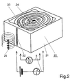
- FIG. 2 shows an embodiment of the magnetic sensor 20 according to the invention as a magnetic field sensor.
- This construction differs in construction from the magnetic sensor 1 according to FIG. 1 in that it is provided with a magnetically shielding encapsulation 21 which has a hydrogen-impermeable magnetic field window 22 and is designed as an annular multilayer package 24 .
- An air gap 23 is aligned with the magnetic field window .
- the interior of the encapsulation 21 (shown broken away) is sealed off from hydrogen so that no hydrogen diffusion can occur between the surroundings and the annular multilayer package 24 .
- the magnetic resistance of the magnetic sensor 20 which is finely tuned to the application by hydrogen loading during manufacture, thus remains constant over a long period of time. If the layers age and the magnetic properties deteriorate, however, the multi-layer package 24 can be separately treated again with hydrogen gas and set to the original magnetoresistance value.
- the physical measurement variable to be measured with this magnetic sensor 20 is the magnetic field strength of an external external magnetic field 25, for example the different magnetizations on a magnetic data carrier.
- This external external magnetic field acts via the hydrogen-impermeable magnetic field window 22 on the magnetic field of the multi-layer package 24 concentrated in the air gap 23 and thus achieves a corresponding change in its electrical resistance, which can be determined again when the constant current I flows by measuring the voltage U (in which Figure is the circuit arrangement 8 indicated).
- the external magnetic field 25 can be variable over time or constant.
- Such magnetic field sensors 20 can completely assume all tasks of previously known field sensors, in particular the tasks in reading heads of any type. Thanks to their simple subsequent fine-tuning via the hydrogen loading of the intermediate layers, they can also be optimally adapted to the respective application in a previously unknown way.
Landscapes
- Engineering & Computer Science (AREA)
- Physics & Mathematics (AREA)
- Chemical & Material Sciences (AREA)
- Nanotechnology (AREA)
- General Physics & Mathematics (AREA)
- Condensed Matter Physics & Semiconductors (AREA)
- Crystallography & Structural Chemistry (AREA)
- Computer Hardware Design (AREA)
- Measuring Magnetic Variables (AREA)
- Investigating Or Analyzing Materials By The Use Of Magnetic Means (AREA)
- Liquid Crystal (AREA)
- Video Image Reproduction Devices For Color Tv Systems (AREA)
- Measurement Of Length, Angles, Or The Like Using Electric Or Magnetic Means (AREA)
- Geophysics And Detection Of Objects (AREA)
Description
- Figur 1
- einen erfindungsgemäßen magnetischen Messfühler in einer
Ausführungsform als Wasserstoff-Detektor
und - Figur 2
- einen erfindungsgemäßen magnetischen Messfühler in einer Ausführung als Magnetfeldsensor.
- 1
- magnetischer Meßfühler
- 2
- Multischichtpaket
- 3
- Substrat
- 4
- ferromagnetische Schicht
- 5
- nichtmagnetische Zwischenschicht
- 6
- Deckschicht
- 7
- Pufferschicht
- 8
- 4-Pol-Widerstandsmeßanordnung
- 9
- 1. Kontaktstelle für Stromaufprägung
- 10
- 2. Kontaktstelle für Stromaufprägung
- 11
- 1. Ecke des Multischichtpakets 2
- 12
- 3. Ecke des Multischichtpakets 2
- 13
- 1. Kontaktstelle für Spannungsabgriff
- 14
- 2. Kontaktstelle für Spannungsabgriff
- 15
- 2. Ecke des Multischichtpakets 2
- 16
- 4. Ecke des Multischichtpakets 2
- 17
- Wasserstoffgasstrom
- 18
- äußeres durchstimmbares Magnetfeld
- d
- Dicke der nichtmagnetischen Zwischenschichten 5
- 20
- magnetischer Meßfühler - Magnetfeldsensor
- 21
- magnetisch abschirmende Kapselung
- 22
- wasserstoffundurchlässiges Magnetfeldfenster
- 23
- Luftspalt
- 24
- ringförmiges Multischichtpaket
- 25
- äußeres Fremdmagnetfeld
Claims (6)
- Magnetischer Messfühler mit durch Wasserstoffbeladung definiert veränderbarem internen, die Differenz des elektrischen Widerstandes bei angelegtem und abgeschaltetem Magnetfeld charakterisierenden Magnetwiderstand, bestehend aus einem Multischichtpaket (2) jeweils sich abwechselnder ferromagnetischer Schichten (4) und wasserstoffaffiner nichtmagnetischer Zwischenschichten (5) auf einem Substrat (3), wobei die Schichten (4) und die Zwischenschichten (5) magnetisch durch den Austausch spinpolarisierter Elektronen gekoppelt sind, und einer Deckschicht (6) aus Pd zur Wasserstoffaktivierung, wobei die nichtmagnetischen Zwischenschichten (5) entweder aus Nb mit einer Schichtdicke (d) zwischen 1,3 nm und 1,6 nm oder aus einer Legierung von Cr mit den Elementen V, Nb oder Ta mit einer Schichtdicke (d) zwischen 0,8 nm und 2,3 nm bestehen.
- Magnetischer Messfühler nach Anspruch 1,
dadurch gekennzeichnet, dass
das Substrat (3) aus Si oder GaAs besteht,
dass die ferromagnetischen Schichten (4) des Multischichtpakets (2) aus Fe, Co oder Ni oder deren Legierungen bestehen, und
dass zwischen dem Substrat (3) und dem Multischichpaket (2) eine Pufferschicht (7) aus Cr vorgesehen ist. - Magnetischer Messfühler nach Anspruch 1 oder 2,
dadurch gekennzeichnet, dass
dieser als Wasserstoff-Detektor oder als Magnetfeldsensor ausgebildet und demselben eine 4-Pol-Meßbrücke zur Messung der Magnetwiderstandsänderung zur Ermittlung der jeweiligen Messgröße zugeordnet ist. - Magnetischer Messfühler nach Anspruch 3,
dadurch gekennzeichnet, dass
dieser (1) als Wasserstoff-Detektor ausgebildet und in einem äußeren durchstimmbaren Magnetfeld (18) angeordnet ist, in dem Veränderungen seines Magnetwiderstandes bestimmbar sind. - Magnetischer Messfühler nach Anspruch 3,
dadurch gekennzeichnet, dass
dieser (20) als Magnetfeldsensor ausgebildet und innerhalb einer magnetisch abschirmenden Kapselung (21) angeordnet ist, die ein wasserstoffundurchlässiges Magnetfeldfenster (22) aufweist. - Magnetischer Messfühler nach Anspruch 5,
dadurch gekennzeichnet, dass
der Magnetfeldsensor (20) ringförmig ausgebildet und mit einem Luftspalt (23) versehen ist, der mit dem wasserstoffundurchlässigen Magnetfeldfenster (22) in der Kapselung (21) fluchtet.
Applications Claiming Priority (3)
| Application Number | Priority Date | Filing Date | Title |
|---|---|---|---|
| DE19706012A DE19706012C2 (de) | 1997-02-09 | 1997-02-09 | Magnetischer Messfühler |
| DE19706012 | 1997-02-09 | ||
| PCT/DE1998/000316 WO1998035240A2 (de) | 1997-02-09 | 1998-02-06 | Magnetischer messfühler |
Publications (2)
| Publication Number | Publication Date |
|---|---|
| EP0958502A2 EP0958502A2 (de) | 1999-11-24 |
| EP0958502B1 true EP0958502B1 (de) | 2003-08-06 |
Family
ID=7820475
Family Applications (1)
| Application Number | Title | Priority Date | Filing Date |
|---|---|---|---|
| EP98910585A Expired - Lifetime EP0958502B1 (de) | 1997-02-09 | 1998-02-06 | Magnetischer messfühler |
Country Status (5)
| Country | Link |
|---|---|
| EP (1) | EP0958502B1 (de) |
| AT (1) | ATE246810T1 (de) |
| AU (1) | AU6494398A (de) |
| DE (2) | DE19706012C2 (de) |
| WO (1) | WO1998035240A2 (de) |
Cited By (1)
| Publication number | Priority date | Publication date | Assignee | Title |
|---|---|---|---|---|
| US9097677B1 (en) | 2014-06-19 | 2015-08-04 | University Of South Florida | Magnetic gas sensors |
Families Citing this family (2)
| Publication number | Priority date | Publication date | Assignee | Title |
|---|---|---|---|---|
| DE10332826A1 (de) | 2003-07-18 | 2005-02-10 | Brandt, Martin S., Dr. | Manipulation der magnetischen Eigenschaften von Halbleitern und magnetoelektronische Bauelemente |
| GB202403134D0 (en) * | 2024-03-04 | 2024-04-17 | Univ Bristol | Hydrogen sensor |
-
1997
- 1997-02-09 DE DE19706012A patent/DE19706012C2/de not_active Expired - Fee Related
-
1998
- 1998-02-06 EP EP98910585A patent/EP0958502B1/de not_active Expired - Lifetime
- 1998-02-06 WO PCT/DE1998/000316 patent/WO1998035240A2/de not_active Ceased
- 1998-02-06 DE DE59809207T patent/DE59809207D1/de not_active Expired - Fee Related
- 1998-02-06 AU AU64943/98A patent/AU6494398A/en not_active Abandoned
- 1998-02-06 AT AT98910585T patent/ATE246810T1/de not_active IP Right Cessation
Cited By (1)
| Publication number | Priority date | Publication date | Assignee | Title |
|---|---|---|---|---|
| US9097677B1 (en) | 2014-06-19 | 2015-08-04 | University Of South Florida | Magnetic gas sensors |
Also Published As
| Publication number | Publication date |
|---|---|
| WO1998035240A2 (de) | 1998-08-13 |
| DE59809207D1 (de) | 2003-09-11 |
| DE19706012C2 (de) | 2000-11-16 |
| WO1998035240A3 (de) | 1998-11-19 |
| AU6494398A (en) | 1998-08-26 |
| DE19706012A1 (de) | 1998-08-20 |
| ATE246810T1 (de) | 2003-08-15 |
| EP0958502A2 (de) | 1999-11-24 |
Similar Documents
| Publication | Publication Date | Title |
|---|---|---|
| DE69425063T2 (de) | Magnetoresistiver linearer weggeber, winkelverschiebungssensor und variabler widerstand | |
| DE69430964T2 (de) | Magnetoresistiver Spinventilfühler und magnetische Anordnung mit solchem Fühler | |
| DE69132027T2 (de) | Magnetoresistiver Fühler | |
| DE69826090T2 (de) | Magnetische Tunnelübergangseinrichtung mit verbesserten ferromagnetischen Schichten | |
| DE69901790T2 (de) | Tunneleffekt-magnetowiderstand und anwendung eines solchen magnetowiderstands in einem magnetischen sensor | |
| DE102019126320B4 (de) | Magnetoresistiver Sensor und Fertigungsverfahren für einen magnetoresistiven Sensor | |
| DE69932800T2 (de) | Anordnung mit einer ersten und einer zweiten ferromagnetischen schicht getrennt durch eine nicht-magnetische abstandsschicht | |
| DE69623577T2 (de) | Mehrschichtstruktur und Sensor sowie Herstellungsverfahren | |
| DE69427536T2 (de) | Geschichtete magnetische struktur | |
| DE4243358A1 (de) | Magnetowiderstands-Sensor mit künstlichem Antiferromagneten und Verfahren zu seiner Herstellung | |
| DE10319319A1 (de) | Sensoreinrichtung mit magnetostriktivem Kraftsensor | |
| DE102016102601B4 (de) | Magnetsensor | |
| DE69934868T2 (de) | Magnetischer mehrschichtsensor | |
| DE69727261T2 (de) | Element mit magnetoresistivem Effekt, sein Herstellungsverfahren und Magnetkopf daraus | |
| DE102007032867A1 (de) | Magnetoresistive Magnetfeldsensorstruktur | |
| DE602004007986T2 (de) | Magnetische Anordnung mit verbesserter Kopplung | |
| DE102019113815B4 (de) | Magnetsensor | |
| DE102016111256B4 (de) | Magnetfeldgenerator, Magnetsensorsystem und Magnetsensor | |
| DE4232244C2 (de) | Magnetowiderstands-Sensor | |
| DE10214946A1 (de) | TMR-Sensor | |
| DE102006008257B4 (de) | Magnetoresistives Mehrschichtensystem vom Spin Valve-Typ mit einer magnetisch weicheren Elektrode aus mehreren Schichten und dessen Verwendung | |
| DE112019006539T5 (de) | Austauschgekoppelter Film und Magnetoresistives Element sowie damit ausgestattete Magnetismus-Erfassungsvorrichtung | |
| DE102006024722A1 (de) | Magnetfelddetektor sowie Verfahren zu seiner Herstellung | |
| DE10128135A1 (de) | Magnetoresistive Schichtanordnung und Gradiometer mit einer derartigen Schichtanordnung | |
| DE69932701T2 (de) | Pinning-Lage für magnetische Anordnungen |
Legal Events
| Date | Code | Title | Description |
|---|---|---|---|
| PUAI | Public reference made under article 153(3) epc to a published international application that has entered the european phase |
Free format text: ORIGINAL CODE: 0009012 |
|
| 17P | Request for examination filed |
Effective date: 19990909 |
|
| AK | Designated contracting states |
Kind code of ref document: A2 Designated state(s): AT BE CH DE DK ES FI FR GB IE IT LI PT |
|
| RBV | Designated contracting states (corrected) |
Designated state(s): AT BE CH DE DK ES FI FR GB IE IT LI PT |
|
| 17Q | First examination report despatched |
Effective date: 20010521 |
|
| GRAH | Despatch of communication of intention to grant a patent |
Free format text: ORIGINAL CODE: EPIDOS IGRA |
|
| GRAH | Despatch of communication of intention to grant a patent |
Free format text: ORIGINAL CODE: EPIDOS IGRA |
|
| GRAA | (expected) grant |
Free format text: ORIGINAL CODE: 0009210 |
|
| AK | Designated contracting states |
Designated state(s): AT BE CH DE DK ES FI FR GB IE IT LI PT |
|
| PG25 | Lapsed in a contracting state [announced via postgrant information from national office to epo] |
Ref country code: IT Free format text: LAPSE BECAUSE OF FAILURE TO SUBMIT A TRANSLATION OF THE DESCRIPTION OR TO PAY THE FEE WITHIN THE PRESCRIBED TIME-LIMIT;WARNING: LAPSES OF ITALIAN PATENTS WITH EFFECTIVE DATE BEFORE 2007 MAY HAVE OCCURRED AT ANY TIME BEFORE 2007. THE CORRECT EFFECTIVE DATE MAY BE DIFFERENT FROM THE ONE RECORDED. Effective date: 20030806 Ref country code: IE Free format text: LAPSE BECAUSE OF FAILURE TO SUBMIT A TRANSLATION OF THE DESCRIPTION OR TO PAY THE FEE WITHIN THE PRESCRIBED TIME-LIMIT Effective date: 20030806 Ref country code: GB Free format text: LAPSE BECAUSE OF FAILURE TO SUBMIT A TRANSLATION OF THE DESCRIPTION OR TO PAY THE FEE WITHIN THE PRESCRIBED TIME-LIMIT Effective date: 20030806 Ref country code: FR Free format text: LAPSE BECAUSE OF FAILURE TO SUBMIT A TRANSLATION OF THE DESCRIPTION OR TO PAY THE FEE WITHIN THE PRESCRIBED TIME-LIMIT Effective date: 20030806 Ref country code: FI Free format text: LAPSE BECAUSE OF FAILURE TO SUBMIT A TRANSLATION OF THE DESCRIPTION OR TO PAY THE FEE WITHIN THE PRESCRIBED TIME-LIMIT Effective date: 20030806 |
|
| REG | Reference to a national code |
Ref country code: GB Ref legal event code: FG4D Free format text: NOT ENGLISH |
|
| REG | Reference to a national code |
Ref country code: CH Ref legal event code: EP |
|
| REG | Reference to a national code |
Ref country code: IE Ref legal event code: FG4D Free format text: GERMAN |
|
| REF | Corresponds to: |
Ref document number: 59809207 Country of ref document: DE Date of ref document: 20030911 Kind code of ref document: P |
|
| PG25 | Lapsed in a contracting state [announced via postgrant information from national office to epo] |
Ref country code: DK Free format text: LAPSE BECAUSE OF FAILURE TO SUBMIT A TRANSLATION OF THE DESCRIPTION OR TO PAY THE FEE WITHIN THE PRESCRIBED TIME-LIMIT Effective date: 20031106 |
|
| PG25 | Lapsed in a contracting state [announced via postgrant information from national office to epo] |
Ref country code: ES Free format text: LAPSE BECAUSE OF FAILURE TO SUBMIT A TRANSLATION OF THE DESCRIPTION OR TO PAY THE FEE WITHIN THE PRESCRIBED TIME-LIMIT Effective date: 20031117 |
|
| PG25 | Lapsed in a contracting state [announced via postgrant information from national office to epo] |
Ref country code: PT Free format text: LAPSE BECAUSE OF FAILURE TO SUBMIT A TRANSLATION OF THE DESCRIPTION OR TO PAY THE FEE WITHIN THE PRESCRIBED TIME-LIMIT Effective date: 20040106 |
|
| GBV | Gb: ep patent (uk) treated as always having been void in accordance with gb section 77(7)/1977 [no translation filed] |
Effective date: 20030806 |
|
| PG25 | Lapsed in a contracting state [announced via postgrant information from national office to epo] |
Ref country code: AT Free format text: LAPSE BECAUSE OF NON-PAYMENT OF DUE FEES Effective date: 20040206 |
|
| PG25 | Lapsed in a contracting state [announced via postgrant information from national office to epo] |
Ref country code: BE Free format text: LAPSE BECAUSE OF NON-PAYMENT OF DUE FEES Effective date: 20040228 |
|
| PG25 | Lapsed in a contracting state [announced via postgrant information from national office to epo] |
Ref country code: LI Free format text: LAPSE BECAUSE OF NON-PAYMENT OF DUE FEES Effective date: 20040229 Ref country code: CH Free format text: LAPSE BECAUSE OF NON-PAYMENT OF DUE FEES Effective date: 20040229 |
|
| REG | Reference to a national code |
Ref country code: IE Ref legal event code: FD4D |
|
| PLBE | No opposition filed within time limit |
Free format text: ORIGINAL CODE: 0009261 |
|
| STAA | Information on the status of an ep patent application or granted ep patent |
Free format text: STATUS: NO OPPOSITION FILED WITHIN TIME LIMIT |
|
| 26N | No opposition filed |
Effective date: 20040507 |
|
| EN | Fr: translation not filed | ||
| BERE | Be: lapsed |
Owner name: *HAHN-MEITNER-INSTITUT BERLIN G.M.B.H. Effective date: 20040228 |
|
| REG | Reference to a national code |
Ref country code: CH Ref legal event code: PL |
|
| PGFP | Annual fee paid to national office [announced via postgrant information from national office to epo] |
Ref country code: DE Payment date: 20070228 Year of fee payment: 10 |
|
| PG25 | Lapsed in a contracting state [announced via postgrant information from national office to epo] |
Ref country code: DE Free format text: LAPSE BECAUSE OF NON-PAYMENT OF DUE FEES Effective date: 20080902 |