EP0958499B1 - Verfahren zum kalibrieren von sensoren in diagnostischen testverfahren - Google Patents
Verfahren zum kalibrieren von sensoren in diagnostischen testverfahren Download PDFInfo
- Publication number
- EP0958499B1 EP0958499B1 EP98905955A EP98905955A EP0958499B1 EP 0958499 B1 EP0958499 B1 EP 0958499B1 EP 98905955 A EP98905955 A EP 98905955A EP 98905955 A EP98905955 A EP 98905955A EP 0958499 B1 EP0958499 B1 EP 0958499B1
- Authority
- EP
- European Patent Office
- Prior art keywords
- sensor
- calibration solution
- calibration
- over time
- container
- Prior art date
- Legal status (The legal status is an assumption and is not a legal conclusion. Google has not performed a legal analysis and makes no representation as to the accuracy of the status listed.)
- Expired - Lifetime
Links
- 238000000034 method Methods 0.000 title claims description 27
- 238000002405 diagnostic procedure Methods 0.000 title description 2
- 239000012482 calibration solution Substances 0.000 claims description 61
- 238000001990 intravenous administration Methods 0.000 claims description 50
- 239000008280 blood Substances 0.000 claims description 37
- 210000004369 blood Anatomy 0.000 claims description 37
- 239000012530 fluid Substances 0.000 claims description 35
- 230000036961 partial effect Effects 0.000 claims description 22
- 238000012360 testing method Methods 0.000 claims description 21
- 239000003978 infusion fluid Substances 0.000 claims description 13
- 238000005086 pumping Methods 0.000 claims description 4
- CURLTUGMZLYLDI-UHFFFAOYSA-N Carbon dioxide Chemical compound O=C=O CURLTUGMZLYLDI-UHFFFAOYSA-N 0.000 description 66
- 239000001569 carbon dioxide Substances 0.000 description 63
- 229910002092 carbon dioxide Inorganic materials 0.000 description 63
- 239000000243 solution Substances 0.000 description 34
- 238000009792 diffusion process Methods 0.000 description 19
- QVGXLLKOCUKJST-UHFFFAOYSA-N atomic oxygen Chemical compound [O] QVGXLLKOCUKJST-UHFFFAOYSA-N 0.000 description 15
- 239000001301 oxygen Substances 0.000 description 15
- 229910052760 oxygen Inorganic materials 0.000 description 15
- 230000008859 change Effects 0.000 description 11
- UIIMBOGNXHQVGW-UHFFFAOYSA-M Sodium bicarbonate Chemical compound [Na+].OC([O-])=O UIIMBOGNXHQVGW-UHFFFAOYSA-M 0.000 description 10
- 150000002500 ions Chemical class 0.000 description 9
- 238000005259 measurement Methods 0.000 description 9
- WQZGKKKJIJFFOK-GASJEMHNSA-N Glucose Natural products OC[C@H]1OC(O)[C@H](O)[C@@H](O)[C@@H]1O WQZGKKKJIJFFOK-GASJEMHNSA-N 0.000 description 8
- 239000008103 glucose Substances 0.000 description 8
- 238000001802 infusion Methods 0.000 description 7
- 239000012528 membrane Substances 0.000 description 7
- VEXZGXHMUGYJMC-UHFFFAOYSA-M Chloride anion Chemical compound [Cl-] VEXZGXHMUGYJMC-UHFFFAOYSA-M 0.000 description 6
- 238000004364 calculation method Methods 0.000 description 6
- 239000007789 gas Substances 0.000 description 6
- 238000005534 hematocrit Methods 0.000 description 6
- DGAQECJNVWCQMB-PUAWFVPOSA-M Ilexoside XXIX Chemical compound C[C@@H]1CC[C@@]2(CC[C@@]3(C(=CC[C@H]4[C@]3(CC[C@@H]5[C@@]4(CC[C@@H](C5(C)C)OS(=O)(=O)[O-])C)C)[C@@H]2[C@]1(C)O)C)C(=O)O[C@H]6[C@@H]([C@H]([C@@H]([C@H](O6)CO)O)O)O.[Na+] DGAQECJNVWCQMB-PUAWFVPOSA-M 0.000 description 5
- 238000013459 approach Methods 0.000 description 5
- 238000012544 monitoring process Methods 0.000 description 5
- 239000011734 sodium Substances 0.000 description 5
- 229910052708 sodium Inorganic materials 0.000 description 5
- 229910000030 sodium bicarbonate Inorganic materials 0.000 description 5
- 241000894007 species Species 0.000 description 5
- OYPRJOBELJOOCE-UHFFFAOYSA-N Calcium Chemical compound [Ca] OYPRJOBELJOOCE-UHFFFAOYSA-N 0.000 description 4
- 239000011575 calcium Substances 0.000 description 4
- 229910052791 calcium Inorganic materials 0.000 description 4
- 230000000694 effects Effects 0.000 description 4
- -1 pH) Chemical compound 0.000 description 4
- 238000010926 purge Methods 0.000 description 4
- 235000017557 sodium bicarbonate Nutrition 0.000 description 4
- BHPQYMZQTOCNFJ-UHFFFAOYSA-N Calcium cation Chemical compound [Ca+2] BHPQYMZQTOCNFJ-UHFFFAOYSA-N 0.000 description 3
- MHAJPDPJQMAIIY-UHFFFAOYSA-N Hydrogen peroxide Chemical compound OO MHAJPDPJQMAIIY-UHFFFAOYSA-N 0.000 description 3
- ZLMJMSJWJFRBEC-UHFFFAOYSA-N Potassium Chemical compound [K] ZLMJMSJWJFRBEC-UHFFFAOYSA-N 0.000 description 3
- FKNQFGJONOIPTF-UHFFFAOYSA-N Sodium cation Chemical compound [Na+] FKNQFGJONOIPTF-UHFFFAOYSA-N 0.000 description 3
- 238000004458 analytical method Methods 0.000 description 3
- 239000013060 biological fluid Substances 0.000 description 3
- 210000004204 blood vessel Anatomy 0.000 description 3
- 239000003792 electrolyte Substances 0.000 description 3
- 230000002209 hydrophobic effect Effects 0.000 description 3
- 239000011591 potassium Substances 0.000 description 3
- 229910052700 potassium Inorganic materials 0.000 description 3
- 229910001415 sodium ion Inorganic materials 0.000 description 3
- BVKZGUZCCUSVTD-UHFFFAOYSA-M Bicarbonate Chemical compound OC([O-])=O BVKZGUZCCUSVTD-UHFFFAOYSA-M 0.000 description 2
- RGHNJXZEOKUKBD-SQOUGZDYSA-N D-gluconic acid Chemical compound OC[C@@H](O)[C@@H](O)[C@H](O)[C@@H](O)C(O)=O RGHNJXZEOKUKBD-SQOUGZDYSA-N 0.000 description 2
- 108010015776 Glucose oxidase Proteins 0.000 description 2
- 239000004366 Glucose oxidase Substances 0.000 description 2
- 206010019133 Hangover Diseases 0.000 description 2
- NPYPAHLBTDXSSS-UHFFFAOYSA-N Potassium ion Chemical compound [K+] NPYPAHLBTDXSSS-UHFFFAOYSA-N 0.000 description 2
- 230000002411 adverse Effects 0.000 description 2
- WQZGKKKJIJFFOK-VFUOTHLCSA-N beta-D-glucose Chemical compound OC[C@H]1O[C@@H](O)[C@H](O)[C@@H](O)[C@@H]1O WQZGKKKJIJFFOK-VFUOTHLCSA-N 0.000 description 2
- BPKIGYQJPYCAOW-FFJTTWKXSA-I calcium;potassium;disodium;(2s)-2-hydroxypropanoate;dichloride;dihydroxide;hydrate Chemical compound O.[OH-].[OH-].[Na+].[Na+].[Cl-].[Cl-].[K+].[Ca+2].C[C@H](O)C([O-])=O BPKIGYQJPYCAOW-FFJTTWKXSA-I 0.000 description 2
- 239000003153 chemical reaction reagent Substances 0.000 description 2
- 230000000875 corresponding effect Effects 0.000 description 2
- 229940116332 glucose oxidase Drugs 0.000 description 2
- 235000019420 glucose oxidase Nutrition 0.000 description 2
- 238000001727 in vivo Methods 0.000 description 2
- 229910052751 metal Inorganic materials 0.000 description 2
- 239000002184 metal Substances 0.000 description 2
- 230000002572 peristaltic effect Effects 0.000 description 2
- 239000002504 physiological saline solution Substances 0.000 description 2
- BASFCYQUMIYNBI-UHFFFAOYSA-N platinum Chemical compound [Pt] BASFCYQUMIYNBI-UHFFFAOYSA-N 0.000 description 2
- 230000009467 reduction Effects 0.000 description 2
- 230000035945 sensitivity Effects 0.000 description 2
- RGHNJXZEOKUKBD-UHFFFAOYSA-N D-gluconic acid Natural products OCC(O)C(O)C(O)C(O)C(O)=O RGHNJXZEOKUKBD-UHFFFAOYSA-N 0.000 description 1
- 241000237858 Gastropoda Species 0.000 description 1
- YZCKVEUIGOORGS-UHFFFAOYSA-N Hydrogen atom Chemical compound [H] YZCKVEUIGOORGS-UHFFFAOYSA-N 0.000 description 1
- JVTAAEKCZFNVCJ-UHFFFAOYSA-M Lactate Chemical compound CC(O)C([O-])=O JVTAAEKCZFNVCJ-UHFFFAOYSA-M 0.000 description 1
- FYYHWMGAXLPEAU-UHFFFAOYSA-N Magnesium Chemical compound [Mg] FYYHWMGAXLPEAU-UHFFFAOYSA-N 0.000 description 1
- 229910021607 Silver chloride Inorganic materials 0.000 description 1
- FAPWRFPIFSIZLT-UHFFFAOYSA-M Sodium chloride Chemical compound [Na+].[Cl-] FAPWRFPIFSIZLT-UHFFFAOYSA-M 0.000 description 1
- 238000010521 absorption reaction Methods 0.000 description 1
- 229910052782 aluminium Inorganic materials 0.000 description 1
- XAGFODPZIPBFFR-UHFFFAOYSA-N aluminium Chemical compound [Al] XAGFODPZIPBFFR-UHFFFAOYSA-N 0.000 description 1
- 239000012491 analyte Substances 0.000 description 1
- 239000007864 aqueous solution Substances 0.000 description 1
- 210000001367 artery Anatomy 0.000 description 1
- 230000000712 assembly Effects 0.000 description 1
- 238000000429 assembly Methods 0.000 description 1
- 230000023555 blood coagulation Effects 0.000 description 1
- 229910001628 calcium chloride Inorganic materials 0.000 description 1
- 229910001424 calcium ion Inorganic materials 0.000 description 1
- 238000006243 chemical reaction Methods 0.000 description 1
- 238000004891 communication Methods 0.000 description 1
- 230000001143 conditioned effect Effects 0.000 description 1
- 238000010276 construction Methods 0.000 description 1
- 238000011109 contamination Methods 0.000 description 1
- 238000012937 correction Methods 0.000 description 1
- 230000002596 correlated effect Effects 0.000 description 1
- 238000010586 diagram Methods 0.000 description 1
- 239000003814 drug Substances 0.000 description 1
- 229940079593 drug Drugs 0.000 description 1
- 239000011888 foil Substances 0.000 description 1
- 239000000174 gluconic acid Substances 0.000 description 1
- 229950006191 gluconic acid Drugs 0.000 description 1
- 235000012208 gluconic acid Nutrition 0.000 description 1
- PCHJSUWPFVWCPO-UHFFFAOYSA-N gold Chemical compound [Au] PCHJSUWPFVWCPO-UHFFFAOYSA-N 0.000 description 1
- 229910052737 gold Inorganic materials 0.000 description 1
- 239000010931 gold Substances 0.000 description 1
- 238000010438 heat treatment Methods 0.000 description 1
- 150000002431 hydrogen Chemical class 0.000 description 1
- 239000001257 hydrogen Substances 0.000 description 1
- 229910052739 hydrogen Inorganic materials 0.000 description 1
- GPRLSGONYQIRFK-UHFFFAOYSA-N hydron Chemical compound [H+] GPRLSGONYQIRFK-UHFFFAOYSA-N 0.000 description 1
- 230000000670 limiting effect Effects 0.000 description 1
- 239000007788 liquid Substances 0.000 description 1
- 230000007774 longterm Effects 0.000 description 1
- 239000011777 magnesium Substances 0.000 description 1
- 229910052749 magnesium Inorganic materials 0.000 description 1
- 239000000463 material Substances 0.000 description 1
- 238000002483 medication Methods 0.000 description 1
- 238000012986 modification Methods 0.000 description 1
- 230000004048 modification Effects 0.000 description 1
- 229910000510 noble metal Inorganic materials 0.000 description 1
- 235000015097 nutrients Nutrition 0.000 description 1
- 230000003647 oxidation Effects 0.000 description 1
- 238000007254 oxidation reaction Methods 0.000 description 1
- 238000001139 pH measurement Methods 0.000 description 1
- 238000004806 packaging method and process Methods 0.000 description 1
- 229910052697 platinum Inorganic materials 0.000 description 1
- 229920001296 polysiloxane Polymers 0.000 description 1
- 229910001414 potassium ion Inorganic materials 0.000 description 1
- 230000008569 process Effects 0.000 description 1
- 230000002829 reductive effect Effects 0.000 description 1
- 230000004044 response Effects 0.000 description 1
- 230000002441 reversible effect Effects 0.000 description 1
- 229910052709 silver Inorganic materials 0.000 description 1
- 239000004332 silver Substances 0.000 description 1
- HKZLPVFGJNLROG-UHFFFAOYSA-M silver monochloride Chemical compound [Cl-].[Ag+] HKZLPVFGJNLROG-UHFFFAOYSA-M 0.000 description 1
- 239000000126 substance Substances 0.000 description 1
- 230000002792 vascular Effects 0.000 description 1
Images
Classifications
-
- G—PHYSICS
- G01—MEASURING; TESTING
- G01N—INVESTIGATING OR ANALYSING MATERIALS BY DETERMINING THEIR CHEMICAL OR PHYSICAL PROPERTIES
- G01N33/00—Investigating or analysing materials by specific methods not covered by groups G01N1/00 - G01N31/00
- G01N33/48—Biological material, e.g. blood, urine; Haemocytometers
- G01N33/483—Physical analysis of biological material
- G01N33/487—Physical analysis of biological material of liquid biological material
- G01N33/49—Blood
- G01N33/4925—Blood measuring blood gas content, e.g. O2, CO2, HCO3
-
- A—HUMAN NECESSITIES
- A61—MEDICAL OR VETERINARY SCIENCE; HYGIENE
- A61B—DIAGNOSIS; SURGERY; IDENTIFICATION
- A61B5/00—Measuring for diagnostic purposes; Identification of persons
- A61B5/145—Measuring characteristics of blood in vivo, e.g. gas concentration or pH-value ; Measuring characteristics of body fluids or tissues, e.g. interstitial fluid or cerebral tissue
- A61B5/14539—Measuring characteristics of blood in vivo, e.g. gas concentration or pH-value ; Measuring characteristics of body fluids or tissues, e.g. interstitial fluid or cerebral tissue for measuring pH
-
- A—HUMAN NECESSITIES
- A61—MEDICAL OR VETERINARY SCIENCE; HYGIENE
- A61B—DIAGNOSIS; SURGERY; IDENTIFICATION
- A61B5/00—Measuring for diagnostic purposes; Identification of persons
- A61B5/145—Measuring characteristics of blood in vivo, e.g. gas concentration or pH-value ; Measuring characteristics of body fluids or tissues, e.g. interstitial fluid or cerebral tissue
- A61B5/14542—Measuring characteristics of blood in vivo, e.g. gas concentration or pH-value ; Measuring characteristics of body fluids or tissues, e.g. interstitial fluid or cerebral tissue for measuring blood gases
-
- A—HUMAN NECESSITIES
- A61—MEDICAL OR VETERINARY SCIENCE; HYGIENE
- A61B—DIAGNOSIS; SURGERY; IDENTIFICATION
- A61B5/00—Measuring for diagnostic purposes; Identification of persons
- A61B5/145—Measuring characteristics of blood in vivo, e.g. gas concentration or pH-value ; Measuring characteristics of body fluids or tissues, e.g. interstitial fluid or cerebral tissue
- A61B5/14546—Measuring characteristics of blood in vivo, e.g. gas concentration or pH-value ; Measuring characteristics of body fluids or tissues, e.g. interstitial fluid or cerebral tissue for measuring analytes not otherwise provided for, e.g. ions, cytochromes
-
- A—HUMAN NECESSITIES
- A61—MEDICAL OR VETERINARY SCIENCE; HYGIENE
- A61B—DIAGNOSIS; SURGERY; IDENTIFICATION
- A61B5/00—Measuring for diagnostic purposes; Identification of persons
- A61B5/145—Measuring characteristics of blood in vivo, e.g. gas concentration or pH-value ; Measuring characteristics of body fluids or tissues, e.g. interstitial fluid or cerebral tissue
- A61B5/1468—Measuring characteristics of blood in vivo, e.g. gas concentration or pH-value ; Measuring characteristics of body fluids or tissues, e.g. interstitial fluid or cerebral tissue using chemical or electrochemical methods, e.g. by polarographic means
-
- A—HUMAN NECESSITIES
- A61—MEDICAL OR VETERINARY SCIENCE; HYGIENE
- A61B—DIAGNOSIS; SURGERY; IDENTIFICATION
- A61B5/00—Measuring for diagnostic purposes; Identification of persons
- A61B5/145—Measuring characteristics of blood in vivo, e.g. gas concentration or pH-value ; Measuring characteristics of body fluids or tissues, e.g. interstitial fluid or cerebral tissue
- A61B5/1495—Calibrating or testing of in-vivo probes
-
- Y—GENERAL TAGGING OF NEW TECHNOLOGICAL DEVELOPMENTS; GENERAL TAGGING OF CROSS-SECTIONAL TECHNOLOGIES SPANNING OVER SEVERAL SECTIONS OF THE IPC; TECHNICAL SUBJECTS COVERED BY FORMER USPC CROSS-REFERENCE ART COLLECTIONS [XRACs] AND DIGESTS
- Y10—TECHNICAL SUBJECTS COVERED BY FORMER USPC
- Y10T—TECHNICAL SUBJECTS COVERED BY FORMER US CLASSIFICATION
- Y10T436/00—Chemistry: analytical and immunological testing
- Y10T436/10—Composition for standardization, calibration, simulation, stabilization, preparation or preservation; processes of use in preparation for chemical testing
- Y10T436/100833—Simulative of a gaseous composition
-
- Y—GENERAL TAGGING OF NEW TECHNOLOGICAL DEVELOPMENTS; GENERAL TAGGING OF CROSS-SECTIONAL TECHNOLOGIES SPANNING OVER SEVERAL SECTIONS OF THE IPC; TECHNICAL SUBJECTS COVERED BY FORMER USPC CROSS-REFERENCE ART COLLECTIONS [XRACs] AND DIGESTS
- Y10—TECHNICAL SUBJECTS COVERED BY FORMER USPC
- Y10T—TECHNICAL SUBJECTS COVERED BY FORMER US CLASSIFICATION
- Y10T436/00—Chemistry: analytical and immunological testing
- Y10T436/10—Composition for standardization, calibration, simulation, stabilization, preparation or preservation; processes of use in preparation for chemical testing
- Y10T436/102499—Blood gas standard or control
Definitions
- This invention relates generally to the diagnostic testing of biological fluids and, more particularly, to the calibrating of sensors used in such testing.
- infusion fluid delivery systems commonly used in hospital patient care.
- Such systems infuse nutrients, medications, and the like directly into the patient at a controlled rate and in precise quantities, for maximum effectiveness.
- Such infusion fluid delivery systems are connected to a patient via an intravenous (IV) port, in which a hollow needle/catheter assembly is inserted into a blood vessel of the patient and thereafter an infusion fluid is introduced into the vessel at a controlled rate, typically using a peristaltic pump.
- IV intravenous
- Blood chemistry monitoring systems that are combined with infusion fluid delivery systems of this kind use the IV port to periodically withdraw a blood sample into an electrode assembly, perform measurements of blood ion concentrations and the like, and then discard the blood or reinfuse it into the patient. The system then resumes delivery of the infusion fluid.
- the electrode assembly typically includes a reference electrode and a plurality of sensing electrodes, or sensors, that are each sensitive to a particular ion or species of interest. All of the electrodes are typically embedded in the base of the electrode assembly. For example, ion-selective electrodes generate electrical signals only in response to contact with the particular ion to which they are sensitive, and therefore provide selective measurement of the amount of that ion in the blood.
- This type of sensing electrode can be provided to measure, for example, blood calcium, hydrogen ion (i.e., pH), chloride, potassium, and sodium.
- the reference electrode might be another ion-selective electrode (e.g., a chloride or sodium electrode) that is continuously exposed to a calibration or reference fluid.
- a conventional reference electrode which maintains a fixed potential when exposed either to reference fluid or to analyte is required.
- Hematocrit is defined as the volume percent of red cells in the blood. Hematocrit can be determined by measuring the blood's ac impedance, using a pair of metal electrodes, typically at 1 kiloHertz (kHz).
- An amperometric sensor produces an electrical current that varies with the concentration of a specific component of interest. For example, oxygen partial pressure (pO 2 ) and glucose (Glu) are commonly determined using amperometric sensors.
- An oxygen sensor assembly usually includes a working electrode formed from a noble metal, e.g., platinum or gold, and a suitable counter electrode formed of a different metal, e.g., silver/silver chloride.
- An oxygen-permeable, but liquid-impermeable, membrane is usually mounted over the sensor assembly, to separate the sample from the internal electrolyte and thereby avoid contamination.
- the sensor measures the limiting current of oxygen reduction at the working electrode according to the following equation: O 2 +2 H 2 O +4 e ⁇ 4OH - This is accomplished by applying a bias voltage of approximately 700mV between the working (negative) electrode and the counter (positive) electrode. The resulting current is proportional to the pO 2 level in the sample.
- the glucose sensor is very similar in construction to the oxygen sensor.
- One difference is that a hydrophilic membrane with immobilized glucose oxidase (i.e., GOD) is used instead of the hydrophobic oxygen membrane.
- GOD glucose oxidase
- the following reaction occurs: Glucose + O 2 + GOD ⁇ GluconicAcid + H 2 O 2
- glucose concentration can be determined by polarizing the working electrode either anodically or cathodically by approximately 700mV, to measure the rate of hydrogen peroxide oxidation or oxygen reduction.
- a potentiometric sensor produces an electrical voltage that varies with the species of interest.
- Ionic species such as hydrogen ion (H + ), sodium (Na + ), potassium (K + ), ionized calcium (Ca ++ ) and chloride (Cl - ), are commonly measured by ion-selective electrodes, a typical class of potentiometric sensors.
- the commonly used CO 2 sensor also is a potentiometric sensor (and is, in fact, essentially a modified pH sensor).
- it consists of a pH electrode and a reference electrode, with both covered by a hydrophobic, gas-permeable/liquid-impermeable membrane such as silicone.
- a thin layer of weakly buffered internal electrolyte e.g., 0.001M NaHCO 3 , is located between the hydrophobic membrane and the pH sensing membrane.
- Carbon dioxide in the sample eventually reaches equilibrium with the internal electrolyte, and it produces a pH shift according to the following equation: CO 2 + H 2 O ⁇ H + + HCO 3 -
- the resulting pH shift is then measured by the pH electrode. Therefore, a direct relationship exists between a sample's CO 2 partial pressure (pCO 2 ) and its pH.
- sensors either are miniaturized and inserted into a blood vessel (in vivo) or are constructed as part of a flow cell connected to the patient end of an existing vascular access port (ex vivo), to provide continuous monitoring of blood chemistry.
- U.S. Patent No. 5,505,828 to Wong et al. describes a calibration solution that is useful for calibrating an array of sensors capable of simultaneously measuring several blood chemistry parameters, including pCO 2 and p 2 O, pH, sodium, potassium, ionized calcium, ionized magnesium, chloride, glucose, lactate, and hematocrit. Moreover, the solution is infusible, whereby it can facilitate calibration on a regular basis of all the sensors in the array, which is in constant fluid communication with the body.
- the Wong et al. calibration solution can function satisfactorily to calibrate pO 2 , because concentration of O 2 in the solution is substantially the same as the concentration of O 2 in the atmosphere and because O therefore will not diffuse from the infusion bag or the IV set.
- concentration of O 2 in the solution is substantially the same as the concentration of O 2 in the atmosphere and because O therefore will not diffuse from the infusion bag or the IV set.
- the amount of dissolved O 2 in the solution varies inversely with the solution's temperature. Consequently, if the solution delivered to the sensor array undergoes a sudden and significant temperature change, some of the dissolved O 2 will come out of solution and calibration errors can arise.
- the present invention resides in a method for calibrating a sensor of a kind that measures the value of a predetermined parameter (e.g., CO 2 partial pressure) of a test fluid such as blood, the method reliably compensating for expected variations over time in the value of the parameter in a calibration solution.
- the parameter of the calibration solution has a predetermined initial value, and the solution is initially located within a container that is configured to allow the value of that parameter to vary over time in a predetermined manner.
- the sensor to be calibrated is exposed to calibration solution supplied from the container, whereupon the sensor produces a calibration solution signal.
- the value of the parameter in the calibration solution supplied to the sensor is calculated based on its expected variation over time, and this calculated concentration is then compared with the calibration solution signal actually produced by the sensor, to produce a calibration factor. Further, the sensor then is exposed to the test fluid, whereupon the sensor produces a test fluid signal. Finally, the test fluid signal is adjusted in accordance with the calibration factor.
- the method of the invention has particular utility as part of an infusion fluid delivery and blood chemistry monitoring system, in which a pump ordinarily pumps the calibration solution from the container to a patient, via a sensor assembly that houses the sensor, whereupon the sensor produces the calibration solution signal. Periodically, the pump reverses its direction and draws blood from the patient into the sensor assembly, whereupon the sensor produces the test fluid signal.
- the method is suitable for use in measuring the value of any parameter whose value in the calibration solution is subject to variation over time. It can be used, for example, with sensors that are sensitive to CO 2 partial pressure, pH, and O 2 pressure.
- CO 2 partial pressure and pH are subject to variation for their initial values, because the container has a porosity that allows CO 2 to escape from the solution until its partial pressure equilibrates with the CO 2 partial pressure of the surrounding atmosphere.
- O 2 partial pressure is subject to variation from its initial value according to temperature variations in the solution.
- the container for the calibration solution includes a flexible bag and an intravenous line.
- the flexible bag allows CO 2 to escape over time from the calibration solution it carries in a first predetermined manner
- the intravenous line allows CO 2 to escape over time from the calibration solution it carries in a second predetermined manner.
- the step of calculating includes calculating the concentration of CO 2 in the calibration solution supplied to the CO 2 sensor based on its expected escape over time from both the flexible bag and the intravenous line. Calculating also includes determining the time durations the calibration solution supplied to the CO 2 sensor has dwelled in both the flexible bag and the intravenous line. Calculating further includes measuring the temperature of the calibration solution in the container and determining the expected escape of CO 2 over time based on the measured temperature.
- the pH sensor is exposed to the calibration solution, whereupon the pH sensor produces a calibration solution pH signal, and the pH of the calibration solution supplied to the pH sensor is calculated based on the expected escape of CO 2 from the container over time. The calculated pH is then compared with the calibration solution pH signal actually produced by the pH sensor, to produce a pH calibration factor.
- the pH sensor also is exposed to the test fluid, whereupon the sensor produces a test fluid pH signal. Finally, the test fluid pH signal is adjusted in accordance with the pH calibration factor.
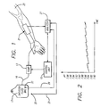
- the apparatus includes a peristaltic infusion pump 13 that is controllably conditioned by a control unit 15 so as to pump an infusion/calibration fluid, or calibrant, from an infusion fluid bag 17 through an intravenous (IV) set or line 19, a sensor assembly 21, and a needle/catheter assembly 23 to the patient 25.
- the control unit periodically conditions the pump to reverse its pumping direction and draw a predetermined amount of blood from the patient back through the needle/catheter assembly to the sensor assembly.
- the control unit conditions the pump to purge the blood from the sensor assembly back into the patient, and then to resume pumping the calibrant at its original controlled rate.
- the sensor assembly 21 includes several individual sensors for measuring any of a number of various blood chemistry parameters. Such parameters can include, for example, hematocrit, glucose concentration, and various ionic concentrations such as sodium ion, potassium ion, calcium ion, and chloride.
- the individual sensors of the sensor assembly also can measure such blood chemistry parameters as pH, carbon dioxide partial pressure (pCO 2 ), and oxygen partial pressure (pO 2 ).
- the various sensors of the sensor assembly 21 must be calibrated, for the signals they produce to have the requisite degree of accuracy.
- Calibration of the ion-sensitive sensors is achieved by formulating the calibrant initially carried in the bag 17 to include prescribed concentrations of various ions, including hydrogen, sodium, potassium, calcium and chloride.
- An analyzer monitors the voltage or current signals produced by these sensors when the calibrant is being pumped through the sensor assembly, so that the sensors' sensitivities can properly be characterized and calibrated.
- Calibrating the CO 2 sensor of the sensor assembly 21 has in the past been a particularly difficult problem, typically requiring the use of bulky gas cylinders and bottles of reagents.
- An improved technique is disclosed in U.S. Patent No. 5,330,634 to Wong et al., wherein a special infusible calibration solution incorporates an amount of sodium bicarbonate effective to provide a prescribed initial concentration of HCO 3 - in the range of about 1 to 100 mm/L.
- the sodium bicarbonate is introduced into the solution from a syringe that is packaged within a gas-impermeable pouch.
- the calibration solution disclosed in the Wong et al. patent works well for time periods of up to about 8 hours; however, over longer periods of time, e.g., 12 to 24 hours, the solution's pH value will rise excessively, and its corresponding pCO 2 will drop excessively. This is due primarily to the diffusion of CO 2 from the bag 17 that initially carries the solution and from the IV set 19 that carries the solution from the bag to the sensor assembly 21. Such diffusion necessarily occurs because the partial pressure of the CO 2 in the calibration solution is initially substantially higher than that of the CO 2 in the surrounding atmosphere. This variation in concentration has led to significant calibration errors.
- a complicating factor in ascertaining the effect on calibration of this CO 2 diffusion is that the diffusion rate from the bag 17 is different from the diffusion rate from the IV set 19, which connects the bag with the sensor assembly 21.
- CO 2 diffuses substantially faster from the it than from the infusion fluid bag.
- FIG. 2 is a graph depicting the rise over time in pH of the calibrant located immediately adjacent to the CO 2 sensor of the sensor assembly 21, due to the diffusion of CO 2 from the calibrant within both the bag 17 and the IV set 19. It will be noted that the pH of the calibrant located adjacent to the CO 2 sensor normally rises at a slow, steady rate while the pump 13 pumps the fluid through the IV set and sensor assembly. During this time, the pH of the calibrant remaining within the bag likewise will rise, but at a significantly slower rate.
- the apparatus 11 of the invention overcomes the problem of CO 2 diffusion by incorporating such diffusion into a calculation of the expected pCO 2 of the calibrant that is at any time disposed adjacent to the CO 2 sensor of the sensor assembly 21.
- a theoretical, multi-compartment model is provided for the IV set 19, whereby the analyzer 27 maintains a running log of the status of each incremental amount of calibrant in the IV set.
- the calibrant in the IV set can be divided into incremental amounts, or slugs, of 1 ml each.
- the calculation of pCO 2 for the slug of calibrant that finally reaches the CO 2 sensor of the sensor assembly 21 takes into account: 1) the diffusion coefficient for the calibrant bag 17, 2) the elapsed time in the bag, 3) the diffusion coefficient for the IV set 19, and 4) the accumulated transit time in the IV set.
- the transit time in the IV set can vary widely depending on the duty cycle involved, ranging from as little as about 10 ml/hour during the normal slow pumping, to as much as 900 ml/hour during purge.
- the calculation of pCO 2 for the slug of calibrant that finally reaches the CO 2 sensor also takes into account the temperature of the calibrant within the bag 17 and the temperature of the ambient atmosphere, which is assumed to be the same as that of the IV set 19.
- the ambient temperature generally is subject to greater variation than is the temperature of the bag.
- the signal produced by the CO 2 sensor generally varies directly with the temperature of the adjacent fluid. Signals indicative of bag temperature and ambient temperature are provided on lines 29 and 31 from temperature sensors 33 and 35, respectively. These temperature sensors conveniently can take the form of thermistors.
- the pCO 2 of the particular incremental amount of calibrant then disposed adjacent to the CO 2 sensor of the sensor assembly 21 is calculated and correlated with the electrical signal then being produced by the sensor. This provides an indication of the CO 2 sensor's sensitivity and provides a calibration factor that can be used subsequently to adjust the signal produced when the patient's blood is withdrawn into the sensor assembly.
- the pH sensor of the sensor assembly 21 is calibrated in an identical manner.
- the pH of the calibrant generally will vary in a predetermined, repeatable fashion with the fluid's pCO 2 .
- an IV set 19 newly put into use will absorb a substantial amount of CO 2 from the calibrant during the first one to two hours.
- the initial pH and pCO 2 of the calibrant are determined primarily by the pH and pCO 2 of the sodium bicarbonate syringe. It is desirable to control these levels so that the apparatus can initiate its operation each time at the same levels. To this end, it is considered desirable to store the syringe in an atmosphere having a predetermined CO 2 level, to stabilize the syringe's pH and CO 2 levels, and then to seal the syringe in a gas-impermeable pouch.
- the ideal gas atmosphere is considered to be 50% ⁇ 20% CO 2 , with the balance N 2 .
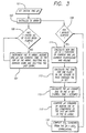
- FIG. 3 is a simplified flowchart of the operational steps implemented by the analyzer 27 in calibrating the CO 2 sensor of the sensor assembly 21.
- a value for the initial pH of the calibrant within the calibrant bag 17 is set. This value is determined based on the known amount of sodium bicarbonate injected into the bag from the syringe.
- a pH table that carries data characterizing each incremental amount, or slug, of calibrant within the IV set 19 is initialized. Initially, the data for each slug should correspond to the pH of the calibrant then carried within the bag.
- the analyzer 27 waits until the pump 13 has pumped a 1 ml slug of calibrant through the IV set 19.
- the pH table is updated at step 107 by shifting all of its entries one step downward and by inserting the current time and the current pH of the fluid within the calibrant bag 17 to the pH table's top-most entry.
- the lower-most entry is deleted, and this process continues indefinitely.
- the lower-most entry in the pH table indicates the time at which the slug of calibrant then adjacent to the CO 2 sensor first entered the IV set, and it further indicates the pH of that slug and the ambient temperature at the time of that entry into the IV set.
- the analyzer 27 While the analyzer 27 is implementing the procedures set forth in steps 105 and 107, as described above, it also determines, at step 109, on a time-interrupt basis, when one minute has elapsed. When it has, the program proceeds to step 111, where an updated pH is calculated for the calibrant still carried within the calibrant bag 17. This calculation takes into account the calculated pH from one minute earlier, the current temperature of the calibrant within the bag, as measured by the thermistor 33, and a calculation of the fluid volume remaining within the bag. It will be appreciated that the temperature of the calibrant within the bag affects the CO 2 diffusion rate and that the remaining calibrant volume affects the magnitude of the effect on pH of a given amount of CO 2 diffusion.
- step 113 the program calculates the amount of time the current slug of calibrant has been in transit within the IV set 19.
- step 115 the program calculates the actual change in pH caused by the calibrant's transit through the IV set. This change is affected, of course, by the dwell time within the IV set, as indicated by the data then carried in the lower-most entry in the IV set table. The change also is affected by the temperature of the calibrant within the IV set, which is assumed to be the arithmetic average of the current ambient temperature and the ambient temperature at the time the current slug of calibrant first entered the IV set.
- step 117 the program calculates the actual pH of the slug of calibrant then disposed adjacent to the CO 2 sensor, by combining the slug's calculated pH when it first entered the IV set 17 with the change in pH that was calculated to have occurred during its transit through the IV set.
- step 119 the program calculates a CO 2 standard based on a correlation of pH with pCO 2 .
- the relationship between pCO 2 and pH is given by the formula (1), set forth above.
- the O 2 sensor of the sensor assembly 21 also needs to be calibrated so that the signal it produces will have the requisite degree of accuracy.
- the amount of dissolved oxygen, i.e., pO 2 in the calibrant carried within the calibrant bag 17 ordinarily is close to that of the surrounding atmosphere.
- dissolved oxygen varies inversely with the temperature at which the fluid is equilibrated.
- the calibrant bag 17 is stored at ambient temperature for a minimum period, say for 24 hours, it is reasonable to assume that the calibrant within the bag will have substantially the same ambient temperature.
- the parameter pO 2 then can be calculated accurately based on that temperature. This calculated value generally is fairly accurate, unless the calibrant undergoes a wide and sudden swing in ambient temperature, such as can occur for example when the bag is transported wich the patient 25 from a relatively cold operating room (OR) to a relatively warm intensive care unit (ICU).
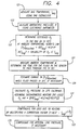
- FIG. 4 is a flowchart of the operational steps implemented by the analyzer 27 in determining the pO 2 of the calibrant located adjacent to the O 2 sensor of the sensor assembly 21.
- step 127 of the program the analyzer 27 measures the ambient temperature T amb and determines the accumulated transit time, t for the particular slug of calibrant that has just reached the O 2 sensor. Then, in step 129, the analyzer estimates the change in pO 2 that has occurred while that slug of calibrant has been disposed within the IV set 19. This change in pO 2 will result from any change in temperature from the temperature of the calibrant within the bag 17, and it is again determined using Henry's Law. This change in temperature is determined by monitoring the temperature of the IV set, which is assumed to correspond to the ambient temperature T amb , as indicated by the signal from the thermistor 35 (FIG. 1).
- F(T amb ,t) represents change in pO 2 during transit through the IV set, and it is determined empirically based on the geometry of the sensor assembly and on the speed at which the calibrant's temperature is raised.
- step 133 the analyzer 27 compensates for any loss due to heating by multiplying this pO 2 value by the following correction factor: (4) 1 - [k * (37 - T bag ) 1 ⁇ 2 ]
- the analyzer 27 compensates for the effects of any positive fluid pressure within the sensor assembly 21.
- a positive pressure might be required, for example, if the apparatus is being used to infuse the calibrant into an artery of the patient 25.
- the present invention provides an improved method for calibrating both a CO 2 sensor and an O 2 sensor that are part of an infusion fluid delivery and blood chemistry analysis apparatus.
- the method provides accurate calibration of these sensors by passing an infusible calibrant past them while correlating their resulting signals with calculated values of the calibrant's pCO 2 and pO 2 . These calculations are specially made based on predetermined diffusion rates for the CO 2 and O 2 from an infusion bag and from an IV set that connects the bag with the sensors.
Landscapes
- Health & Medical Sciences (AREA)
- Life Sciences & Earth Sciences (AREA)
- Physics & Mathematics (AREA)
- Engineering & Computer Science (AREA)
- Biomedical Technology (AREA)
- General Health & Medical Sciences (AREA)
- Pathology (AREA)
- Biophysics (AREA)
- Molecular Biology (AREA)
- Medical Informatics (AREA)
- Veterinary Medicine (AREA)
- Public Health (AREA)
- Animal Behavior & Ethology (AREA)
- Surgery (AREA)
- Heart & Thoracic Surgery (AREA)
- Optics & Photonics (AREA)
- Chemical & Material Sciences (AREA)
- Hematology (AREA)
- Urology & Nephrology (AREA)
- General Physics & Mathematics (AREA)
- Biochemistry (AREA)
- Ecology (AREA)
- Analytical Chemistry (AREA)
- Medicinal Chemistry (AREA)
- Food Science & Technology (AREA)
- Immunology (AREA)
- Chemical Kinetics & Catalysis (AREA)
- General Chemical & Material Sciences (AREA)
- Measurement Of The Respiration, Hearing Ability, Form, And Blood Characteristics Of Living Organisms (AREA)
- Investigating Or Analysing Biological Materials (AREA)
Claims (10)
- Verfahren zum Kalibrieren eines Sensors eines Typs, der einen vorbestimmten Parameter eines Testfluids mißt, umfassend:Geben einer Kalibrierungslösung in ein Behältnis, in welchem ein vorbestimmter Parameter der Kalibrierungslösung einen vorbestimmten Wert aufweist, und wobei das Behältnis derart konfiguriert wird, daß der Wert des vorbestimmten Parameters zeitlich auf eine vorbestimmte Weise variieren kann;Aussetzen des Sensors der vom Behältnis zugeführten Kalibrierungslösung, woraufhin der Sensor ein Kalibrierungslösungs-Signal erzeugt;Berechnen des Werts des vorbestimmten Parameters der dem Sensor zugeführten Kalibrierungslösung auf der Grundlage dessen erwarteter zeitlicher Variation und Vergleichen des berechneten Werts mit dem tatsächlich vom Sensor erzeugten Kalibrierungslösungs-Signal, um einen Kalibrierungsfaktor zu erzeugen;Aussetzen des Sensors dem Testfluid, woraufhin der Sensor ein Testfluid-Signal erzeugt; undAnpassen des Test-Fluidsignals entsprechend dem Kalibrierungsfaktor, um ein kalibriertes Testfluid-Signal zu erzeugen.
- Verfahren nach Anspruch 1, in welchem:die Kalibrierungslösung in einen Patienten infundierbar ist;das Testfluid Blut ist;das Verfahren als Teil einer Infusionsfluid-Abgabevorrichtung implementiert ist, welche einen Sensoranordnung umfaßt, die einen CO2 Sensor aufnimmt;der Schritt des Aussetzens vom Sensor der Kalibrierungslösung das Pumpen der Kalibrierungslösung durch die Sensoranordnung und in den Patienten umfaßt; undder Schritt des Aussetzens des Sensors dem Testfluid das Ziehen von Blut aus dem Patienten in die Sensoranordnung umfaßt.
- Verfahrens nach Anspruch 1 oder 2, in welchem:der vorbestimmte Parameter des zu messenden Testfluids der CO2 Partialdruck ist;der Sensor zur Messung des CO2 Partialdrucks konfiguriert wird;die Kalibrierungslösung eine vorbestimmte anfängliche CO2 Konzentration aufweist;das Behältnis eine Porosität aufweist, dies es gestattet, daß CO2 im Verlaufe der Zeit auf eine vorbestimmte Weise aus der Kalibrierungslösung entweicht; undder Berechnungschritt die Berechnung der CO2 Konzentration in der dem CO2 Sensor zugeführten Kalibrierungslösung auf der Grundlage deren erwartetem Entweichen aus dem Behältnis im Verlaufe der Zeit umfaßt.
- Verfahren nach einem der Ansprüche 1 bis 3, in welchem
der Sensor zur Messung des pH's konfiguriert ist;
die Kalibrierungslösung eine vorbestimmte anfängliche CO2 Konzentration aufweist;
das Behältnis eine Porosität aufweist, die es gestattet, daß CO2 im Verlaufe der Zeit auf eine vorbestimmte Weise aus der Kalibrierungslösung entweicht; und
der Berechnungschritt umfaßt:die Berechnung der CO2 Konzentration in der dem pH Sensor zugeführten Kalibrierungslösung auf der Grundlage deren erwartetem Entweichen aus dem Behältnis im Verlaufe der Zeit unddie Berechnung des pH's der dem pH Sensor zugeführten Kalibrierungslösung auf der Grundlage der berechneten CO2 Konzentration. - Verfahren nach einem der Ansprüche 1, 2, 3 oder 4, in welchem
der vorbestimmte Parameter des zu messenden Testfluids der O2 Partialdruck ist;
der Sensor zur Messung des O2 Partialdrucks konfiguriert wird;
die Kalibrierungslösung eine vorbestimmte anfängliche O2 Konzentration aufweist;
das Verfahren ferner einen Schritt der Messung der Temperatur der vom Behältnis geführten Kalibrierungslösung umfaßt;
das Behältnis eine Porosität aufweist, dies es gestattet, daß der O2 Partialdruck der von ihm geführten Kalibrierungslösung im Verlaufe der Zeit auf eine vorbestimmte Weise entsprechend Variationen der Temperatur der Kalibrierungslösung variiert; und
der Berechnungschritt die Berechnung des O2 Partialdrucks in der dem O2 Sensor zugeführten Kalibrierungslösung auf der Grundlage der gemessenen Temperatur der Kalibrierungslösung umfaßt. - Verfahren nach einem der Ansprüche 1 bis 5, in welchem
das Behältnis für die Kalibrierungslösung einen flexiblen Beutel und eine intravenöse Zuleitung umfaßt;
der flexible Beutel es gestattet, daß CO2 im Verlaufe der Zeit auf eine erste vorbestimmte Weise aus der von ihm geführten Kalibrierungslösung entweicht, und die intravenöse Zuleitung es gestattet, daß CO2 im Verlaufe der Zeit auf eine zweite vorbestimmte Weise aus der von ihr geführten Kalibrierungslösung entweicht; und
der Berechnungschritt die Berechnung der CO2 Konzentration in der dem CO2 Sensor zugeführten Kalibrierungslösung auf der Grundlage deren erwartetem Entweichen im Verlaufe der Zeit sowohl aus dem flexiblen Beutel als auch der intravenösen Zuleitung umfaßt. - Verfahren nach einem der Ansprüche 1 bis 6, in welchem der Berechnungsschritt die Ermittelung der Zeitdauern umfaßt, in denen die dem CO2 Sensor zugeführte Kalibrierungslösung sowohl im flexiblen Beutel als auch in der intravenösen Zuleitung verweilt hat.
- Verfahren nach einem der Ansprüche 1 bis 7, in welchem der Berechnungsschritt eine Messung der Temperatur der Kalibrierungslösung im Behältnis und die Ermittelung des erwarteten Entweichens von CO2 im Verlaufe der Zeit auf der Grundlage der gemessenen Temperatur umfaßt.
- Verfahren nach einem der Ansprüche 1 bis 8, umfassend:Aussetzen eines zweiten, auf pH ansprechenden Sensors der Kalibrierungslösung, woraufhin der zweite auf pH ansprechende Sensor ein Kalibrierungslösungs-pH-Signal erzeugt;Berechnen des pH der dem zweiten auf pH ansprechenden Sensor zugeführten Kalibrierungslösung auf der Grundlage des erwarteten Entweichens von CO2 aus dem Behältnis im Verlaufe der Zeit, und Vergleichen des berechneten pH's mit dem tatsächlich vom zweiten auf pH ansprechenden Sensor erzeugten Kalibrierungslösungs-pH-Signal, um einen pH-Kalibrierungsfaktor zu erzeugen;Aussetzen des zweiten auf pH ansprechenden Sensors dem Testfluid, woraufhin der Sensor ein Testfluid-pH-Signal erzeugt; undAnpassen des Test-pH-Fluidsignals entsprechend dem pH-Kalibrierungsfaktor.
- Verfahren nach einem der Ansprüche 1 bis 9 und ferner umfassend:Messen des Drucks der Umgebung; undAnpassen des berechneten Werts des O2 Partialdrucks der Kalibrierungslösung auf der Grundlage des gemessenen Drucks der Umgebung.
Applications Claiming Priority (3)
| Application Number | Priority Date | Filing Date | Title |
|---|---|---|---|
| US78394497A | 1997-01-17 | 1997-01-17 | |
| US783944 | 1997-01-17 | ||
| PCT/US1998/000702 WO1998032013A1 (en) | 1997-01-17 | 1998-01-14 | Method for calibrating sensors used in diagnostic testing |
Publications (2)
| Publication Number | Publication Date |
|---|---|
| EP0958499A1 EP0958499A1 (de) | 1999-11-24 |
| EP0958499B1 true EP0958499B1 (de) | 2002-08-07 |
Family
ID=25130895
Family Applications (1)
| Application Number | Title | Priority Date | Filing Date |
|---|---|---|---|
| EP98905955A Expired - Lifetime EP0958499B1 (de) | 1997-01-17 | 1998-01-14 | Verfahren zum kalibrieren von sensoren in diagnostischen testverfahren |
Country Status (5)
| Country | Link |
|---|---|
| US (1) | US6123827A (de) |
| EP (1) | EP0958499B1 (de) |
| JP (1) | JP3121356B2 (de) |
| DE (1) | DE69807042T2 (de) |
| WO (1) | WO1998032013A1 (de) |
Families Citing this family (154)
| Publication number | Priority date | Publication date | Assignee | Title |
|---|---|---|---|---|
| US7885697B2 (en) | 2004-07-13 | 2011-02-08 | Dexcom, Inc. | Transcutaneous analyte sensor |
| US6467953B1 (en) * | 1999-03-30 | 2002-10-22 | Medical Solutions, Inc. | Method and apparatus for monitoring temperature of intravenously delivered fluids and other medical items |
| US8480580B2 (en) | 1998-04-30 | 2013-07-09 | Abbott Diabetes Care Inc. | Analyte monitoring device and methods of use |
| US8974386B2 (en) | 1998-04-30 | 2015-03-10 | Abbott Diabetes Care Inc. | Analyte monitoring device and methods of use |
| US8346337B2 (en) | 1998-04-30 | 2013-01-01 | Abbott Diabetes Care Inc. | Analyte monitoring device and methods of use |
| US8688188B2 (en) | 1998-04-30 | 2014-04-01 | Abbott Diabetes Care Inc. | Analyte monitoring device and methods of use |
| US9066695B2 (en) | 1998-04-30 | 2015-06-30 | Abbott Diabetes Care Inc. | Analyte monitoring device and methods of use |
| US6949816B2 (en) | 2003-04-21 | 2005-09-27 | Motorola, Inc. | Semiconductor component having first surface area for electrically coupling to a semiconductor chip and second surface area for electrically coupling to a substrate, and method of manufacturing same |
| US6175752B1 (en) | 1998-04-30 | 2001-01-16 | Therasense, Inc. | Analyte monitoring device and methods of use |
| US8465425B2 (en) | 1998-04-30 | 2013-06-18 | Abbott Diabetes Care Inc. | Analyte monitoring device and methods of use |
| US6128519A (en) * | 1998-12-16 | 2000-10-03 | Pepex Biomedical, Llc | System and method for measuring a bioanalyte such as lactate |
| US7194371B1 (en) * | 2000-03-27 | 2007-03-20 | Cardiobeat.Com | Medical testing system and method |
| UA74188C2 (uk) * | 2000-06-01 | 2005-11-15 | Бп Кемікалз Лімітед | Поліетиленові плівки |
| CN100346158C (zh) | 2000-11-30 | 2007-10-31 | 松下电器产业株式会社 | 基质的定量方法 |
| US6560471B1 (en) | 2001-01-02 | 2003-05-06 | Therasense, Inc. | Analyte monitoring device and methods of use |
| US7238171B2 (en) | 2001-03-12 | 2007-07-03 | Medical Solutions, Inc. | Method and apparatus for controlling pressurized infusion and temperature of infused liquids |
| ATE487130T1 (de) | 2001-08-22 | 2010-11-15 | Instrumentation Lab Co | Verfahren und vorrichtung zur kalibrierung von sensoren |
| US8260393B2 (en) | 2003-07-25 | 2012-09-04 | Dexcom, Inc. | Systems and methods for replacing signal data artifacts in a glucose sensor data stream |
| US9282925B2 (en) | 2002-02-12 | 2016-03-15 | Dexcom, Inc. | Systems and methods for replacing signal artifacts in a glucose sensor data stream |
| US7613491B2 (en) | 2002-05-22 | 2009-11-03 | Dexcom, Inc. | Silicone based membranes for use in implantable glucose sensors |
| US8010174B2 (en) | 2003-08-22 | 2011-08-30 | Dexcom, Inc. | Systems and methods for replacing signal artifacts in a glucose sensor data stream |
| US8364229B2 (en) | 2003-07-25 | 2013-01-29 | Dexcom, Inc. | Analyte sensors having a signal-to-noise ratio substantially unaffected by non-constant noise |
| US9247901B2 (en) | 2003-08-22 | 2016-02-02 | Dexcom, Inc. | Systems and methods for replacing signal artifacts in a glucose sensor data stream |
| AU2003234944A1 (en) * | 2002-08-27 | 2004-03-18 | Bayer Healthcare, Llc | Methods of Determining Glucose Concentration in Whole Blood Samples |
| US9763609B2 (en) | 2003-07-25 | 2017-09-19 | Dexcom, Inc. | Analyte sensors having a signal-to-noise ratio substantially unaffected by non-constant noise |
| US8423113B2 (en) | 2003-07-25 | 2013-04-16 | Dexcom, Inc. | Systems and methods for processing sensor data |
| US8676287B2 (en) | 2003-08-01 | 2014-03-18 | Dexcom, Inc. | System and methods for processing analyte sensor data |
| US9135402B2 (en) | 2007-12-17 | 2015-09-15 | Dexcom, Inc. | Systems and methods for processing sensor data |
| US7591801B2 (en) | 2004-02-26 | 2009-09-22 | Dexcom, Inc. | Integrated delivery device for continuous glucose sensor |
| US8626257B2 (en) | 2003-08-01 | 2014-01-07 | Dexcom, Inc. | Analyte sensor |
| US20190357827A1 (en) | 2003-08-01 | 2019-11-28 | Dexcom, Inc. | Analyte sensor |
| US8369919B2 (en) | 2003-08-01 | 2013-02-05 | Dexcom, Inc. | Systems and methods for processing sensor data |
| US8761856B2 (en) | 2003-08-01 | 2014-06-24 | Dexcom, Inc. | System and methods for processing analyte sensor data |
| US8275437B2 (en) | 2003-08-01 | 2012-09-25 | Dexcom, Inc. | Transcutaneous analyte sensor |
| US8160669B2 (en) | 2003-08-01 | 2012-04-17 | Dexcom, Inc. | Transcutaneous analyte sensor |
| US7276029B2 (en) | 2003-08-01 | 2007-10-02 | Dexcom, Inc. | System and methods for processing analyte sensor data |
| US20080119703A1 (en) | 2006-10-04 | 2008-05-22 | Mark Brister | Analyte sensor |
| US7774145B2 (en) | 2003-08-01 | 2010-08-10 | Dexcom, Inc. | Transcutaneous analyte sensor |
| US8886273B2 (en) | 2003-08-01 | 2014-11-11 | Dexcom, Inc. | Analyte sensor |
| US8845536B2 (en) | 2003-08-01 | 2014-09-30 | Dexcom, Inc. | Transcutaneous analyte sensor |
| US7959569B2 (en) | 2003-08-01 | 2011-06-14 | Dexcom, Inc. | System and methods for processing analyte sensor data |
| US8233959B2 (en) | 2003-08-22 | 2012-07-31 | Dexcom, Inc. | Systems and methods for processing analyte sensor data |
| US20140121989A1 (en) | 2003-08-22 | 2014-05-01 | Dexcom, Inc. | Systems and methods for processing analyte sensor data |
| US7920906B2 (en) | 2005-03-10 | 2011-04-05 | Dexcom, Inc. | System and methods for processing analyte sensor data for sensor calibration |
| US8615282B2 (en) | 2004-07-13 | 2013-12-24 | Dexcom, Inc. | Analyte sensor |
| WO2005051170A2 (en) | 2003-11-19 | 2005-06-09 | Dexcom, Inc. | Integrated receiver for continuous analyte sensor |
| US9247900B2 (en) | 2004-07-13 | 2016-02-02 | Dexcom, Inc. | Analyte sensor |
| US8425416B2 (en) | 2006-10-04 | 2013-04-23 | Dexcom, Inc. | Analyte sensor |
| US8364230B2 (en) | 2006-10-04 | 2013-01-29 | Dexcom, Inc. | Analyte sensor |
| US8423114B2 (en) | 2006-10-04 | 2013-04-16 | Dexcom, Inc. | Dual electrode system for a continuous analyte sensor |
| US8287453B2 (en) | 2003-12-05 | 2012-10-16 | Dexcom, Inc. | Analyte sensor |
| US11633133B2 (en) | 2003-12-05 | 2023-04-25 | Dexcom, Inc. | Dual electrode system for a continuous analyte sensor |
| US20080200788A1 (en) * | 2006-10-04 | 2008-08-21 | Dexcorn, Inc. | Analyte sensor |
| US8425417B2 (en) | 2003-12-05 | 2013-04-23 | Dexcom, Inc. | Integrated device for continuous in vivo analyte detection and simultaneous control of an infusion device |
| WO2005057168A2 (en) | 2003-12-05 | 2005-06-23 | Dexcom, Inc. | Calibration techniques for a continuous analyte sensor |
| US8364231B2 (en) | 2006-10-04 | 2013-01-29 | Dexcom, Inc. | Analyte sensor |
| EP3263032B1 (de) | 2003-12-09 | 2024-01-24 | Dexcom, Inc. | Signalverarbeitung in einem durchgehenden analytsensor |
| US8808228B2 (en) | 2004-02-26 | 2014-08-19 | Dexcom, Inc. | Integrated medicament delivery device for use with continuous analyte sensor |
| US7783333B2 (en) | 2004-07-13 | 2010-08-24 | Dexcom, Inc. | Transcutaneous medical device with variable stiffness |
| US20060016700A1 (en) | 2004-07-13 | 2006-01-26 | Dexcom, Inc. | Transcutaneous analyte sensor |
| WO2006127694A2 (en) | 2004-07-13 | 2006-11-30 | Dexcom, Inc. | Analyte sensor |
| US8452368B2 (en) | 2004-07-13 | 2013-05-28 | Dexcom, Inc. | Transcutaneous analyte sensor |
| US8565848B2 (en) | 2004-07-13 | 2013-10-22 | Dexcom, Inc. | Transcutaneous analyte sensor |
| US7608042B2 (en) | 2004-09-29 | 2009-10-27 | Intellidx, Inc. | Blood monitoring system |
| US7972279B2 (en) | 2005-01-27 | 2011-07-05 | Instrumentation Laboratory Company | Method and system for managing patient data |
| US7722537B2 (en) * | 2005-02-14 | 2010-05-25 | Optiscan Biomedical Corp. | Method and apparatus for detection of multiple analytes |
| US20070123801A1 (en) * | 2005-11-28 | 2007-05-31 | Daniel Goldberger | Wearable, programmable automated blood testing system |
| US8092385B2 (en) | 2006-05-23 | 2012-01-10 | Intellidx, Inc. | Fluid access interface |
| WO2007143225A2 (en) | 2006-06-07 | 2007-12-13 | Abbott Diabetes Care, Inc. | Analyte monitoring system and method |
| US8447376B2 (en) | 2006-10-04 | 2013-05-21 | Dexcom, Inc. | Analyte sensor |
| US8478377B2 (en) | 2006-10-04 | 2013-07-02 | Dexcom, Inc. | Analyte sensor |
| US8562528B2 (en) | 2006-10-04 | 2013-10-22 | Dexcom, Inc. | Analyte sensor |
| US8275438B2 (en) | 2006-10-04 | 2012-09-25 | Dexcom, Inc. | Analyte sensor |
| US8449464B2 (en) | 2006-10-04 | 2013-05-28 | Dexcom, Inc. | Analyte sensor |
| US8298142B2 (en) | 2006-10-04 | 2012-10-30 | Dexcom, Inc. | Analyte sensor |
| US8417311B2 (en) | 2008-09-12 | 2013-04-09 | Optiscan Biomedical Corporation | Fluid component analysis system and method for glucose monitoring and control |
| US20200037874A1 (en) | 2007-05-18 | 2020-02-06 | Dexcom, Inc. | Analyte sensors having a signal-to-noise ratio substantially unaffected by non-constant noise |
| US20080306434A1 (en) | 2007-06-08 | 2008-12-11 | Dexcom, Inc. | Integrated medicament delivery device for use with continuous analyte sensor |
| EP4159114B1 (de) | 2007-10-09 | 2024-04-10 | DexCom, Inc. | Integriertes insulin-abgabesystem mit kontinuierlichem glucosesensor |
| JP5587782B2 (ja) | 2007-10-10 | 2014-09-10 | オプテイスカン・バイオメデイカル・コーポレーシヨン | グルコースのモニターおよび調節のための流体成分分析システムおよび方法 |
| US8417312B2 (en) | 2007-10-25 | 2013-04-09 | Dexcom, Inc. | Systems and methods for processing sensor data |
| US8290559B2 (en) | 2007-12-17 | 2012-10-16 | Dexcom, Inc. | Systems and methods for processing sensor data |
| CA2715628A1 (en) | 2008-02-21 | 2009-08-27 | Dexcom, Inc. | Systems and methods for processing, transmitting and displaying sensor data |
| US8396528B2 (en) | 2008-03-25 | 2013-03-12 | Dexcom, Inc. | Analyte sensor |
| US8523797B2 (en) * | 2008-05-08 | 2013-09-03 | Hospira, Inc. | Automated point-of-care fluid testing device and method of using the same |
| US7959598B2 (en) | 2008-08-20 | 2011-06-14 | Asante Solutions, Inc. | Infusion pump systems and methods |
| US8753290B2 (en) | 2009-03-27 | 2014-06-17 | Intellectual Inspiration, Llc | Fluid transfer system and method |
| WO2010111660A1 (en) | 2009-03-27 | 2010-09-30 | Dexcom, Inc. | Methods and systems for promoting glucose management |
| ES2847578T3 (es) | 2011-04-15 | 2021-08-03 | Dexcom Inc | Calibración avanzada de sensor de analito y detección de errores |
| WO2012159040A2 (en) | 2011-05-19 | 2012-11-22 | Pepex Biomedical Inc. | Fluid management and patient monitoring system |
| US9211381B2 (en) | 2012-01-20 | 2015-12-15 | Medical Solutions, Inc. | Method and apparatus for controlling temperature of medical liquids |
| US9656029B2 (en) | 2013-02-15 | 2017-05-23 | Medical Solutions, Inc. | Plural medical item warming system and method for warming a plurality of medical items to desired temperatures |
| US9561324B2 (en) | 2013-07-19 | 2017-02-07 | Bigfoot Biomedical, Inc. | Infusion pump system and method |
| US20150133861A1 (en) | 2013-11-11 | 2015-05-14 | Kevin P. McLennan | Thermal management system and method for medical devices |
| GB2523989B (en) | 2014-01-30 | 2020-07-29 | Insulet Netherlands B V | Therapeutic product delivery system and method of pairing |
| US10143795B2 (en) | 2014-08-18 | 2018-12-04 | Icu Medical, Inc. | Intravenous pole integrated power, control, and communication system and method for an infusion pump |
| CN107405446B (zh) | 2015-02-18 | 2020-09-29 | 英赛罗公司 | 流体输送和输注装置及其使用方法 |
| AU2016267763B2 (en) | 2015-05-26 | 2021-07-08 | Icu Medical, Inc. | Disposable infusion fluid delivery device for programmable large volume drug delivery |
| WO2017072346A1 (en) * | 2015-10-30 | 2017-05-04 | F. Hoffmann-La Roche Ag | Identification of calibration deviations of ph-measuring devices |
| EP3374905A1 (de) | 2016-01-13 | 2018-09-19 | Bigfoot Biomedical, Inc. | Benutzerschnittstelle für diabetesmanagementsystem |
| WO2017123703A2 (en) | 2016-01-14 | 2017-07-20 | Bigfoot Biomedical, Inc. | Occlusion resolution in medication delivery devices, systems, and methods |
| US10806859B2 (en) | 2016-01-14 | 2020-10-20 | Bigfoot Biomedical, Inc. | Adjusting insulin delivery rates |
| US12383166B2 (en) | 2016-05-23 | 2025-08-12 | Insulet Corporation | Insulin delivery system and methods with risk-based set points |
| EP3515535A1 (de) | 2016-09-23 | 2019-07-31 | Insulet Corporation | Flüssigkeitsabgabevorrichtung mit sensor |
| WO2018104134A1 (en) * | 2016-12-07 | 2018-06-14 | Radiometer Medical Aps | System and method for estimating a temperature of a liquid sample |
| CN109922716A (zh) | 2016-12-12 | 2019-06-21 | 比格福特生物医药公司 | 药物输送设备的警报和警惕以及相关的系统和方法 |
| US10758675B2 (en) | 2017-01-13 | 2020-09-01 | Bigfoot Biomedical, Inc. | System and method for adjusting insulin delivery |
| US10500334B2 (en) | 2017-01-13 | 2019-12-10 | Bigfoot Biomedical, Inc. | System and method for adjusting insulin delivery |
| US10881793B2 (en) | 2017-01-13 | 2021-01-05 | Bigfoot Biomedical, Inc. | System and method for adjusting insulin delivery |
| US10610644B2 (en) | 2017-01-13 | 2020-04-07 | Bigfoot Biomedical, Inc. | Insulin delivery methods, systems and devices |
| US11033682B2 (en) | 2017-01-13 | 2021-06-15 | Bigfoot Biomedical, Inc. | Insulin delivery methods, systems and devices |
| US10583250B2 (en) | 2017-01-13 | 2020-03-10 | Bigfoot Biomedical, Inc. | System and method for adjusting insulin delivery |
| US10552580B2 (en) * | 2017-02-07 | 2020-02-04 | Medtronic Minimed, Inc. | Infusion system consumables and related calibration methods |
| WO2019083939A1 (en) | 2017-10-24 | 2019-05-02 | Dexcom, Inc. | PRECONNECTED ANALYTE SENSORS |
| US11331022B2 (en) | 2017-10-24 | 2022-05-17 | Dexcom, Inc. | Pre-connected analyte sensors |
| USD928199S1 (en) | 2018-04-02 | 2021-08-17 | Bigfoot Biomedical, Inc. | Medication delivery device with icons |
| EP3788628B1 (de) | 2018-05-04 | 2024-12-11 | Insulet Corporation | Sicherheitsbeschränkungen für ein wirkstofffreisetzungssystem auf steueralgorithmusbasis |
| US12562251B1 (en) | 2018-05-09 | 2026-02-24 | Bigfoot Biomedical, Inc. | Computing architecture for assuring the provenance of medication therapy related parameters, and related systems, methods and devices |
| CN112789070A (zh) | 2018-09-28 | 2021-05-11 | 英赛罗公司 | 人造胰腺系统的活动模式 |
| US11565039B2 (en) | 2018-10-11 | 2023-01-31 | Insulet Corporation | Event detection for drug delivery system |
| USD920343S1 (en) | 2019-01-09 | 2021-05-25 | Bigfoot Biomedical, Inc. | Display screen or portion thereof with graphical user interface associated with insulin delivery |
| US12031941B2 (en) * | 2019-08-12 | 2024-07-09 | Emd Millipore Corporation | Methods to automatically calibrate pH sensors without sampling |
| USD939079S1 (en) | 2019-08-22 | 2021-12-21 | Icu Medical, Inc. | Infusion pump |
| US11801344B2 (en) | 2019-09-13 | 2023-10-31 | Insulet Corporation | Blood glucose rate of change modulation of meal and correction insulin bolus quantity |
| US11935637B2 (en) | 2019-09-27 | 2024-03-19 | Insulet Corporation | Onboarding and total daily insulin adaptivity |
| WO2021113647A1 (en) | 2019-12-06 | 2021-06-10 | Insulet Corporation | Techniques and devices providing adaptivity and personalization in diabetes treatment |
| US11833329B2 (en) | 2019-12-20 | 2023-12-05 | Insulet Corporation | Techniques for improved automatic drug delivery performance using delivery tendencies from past delivery history and use patterns |
| AU2021206190A1 (en) | 2020-01-06 | 2022-08-18 | Insulet Corporation | Prediction of meal and/or exercise events based on persistent residuals |
| EP4100958A1 (de) | 2020-02-03 | 2022-12-14 | Insulet Corporation | Einsatz von fuzzy-logik beim vorhersagen von benutzerverhalten, das die blutzuckerkonzentration beeinflusst |
| US11551802B2 (en) | 2020-02-11 | 2023-01-10 | Insulet Corporation | Early meal detection and calorie intake detection |
| US11986630B2 (en) | 2020-02-12 | 2024-05-21 | Insulet Corporation | Dual hormone delivery system for reducing impending hypoglycemia and/or hyperglycemia risk |
| US11547800B2 (en) | 2020-02-12 | 2023-01-10 | Insulet Corporation | User parameter dependent cost function for personalized reduction of hypoglycemia and/or hyperglycemia in a closed loop artificial pancreas system |
| US11324889B2 (en) | 2020-02-14 | 2022-05-10 | Insulet Corporation | Compensation for missing readings from a glucose monitor in an automated insulin delivery system |
| US12495994B2 (en) | 2020-02-20 | 2025-12-16 | Insulet Corporation | Meal bolus subcategories in model based insulin therapy |
| US11607493B2 (en) | 2020-04-06 | 2023-03-21 | Insulet Corporation | Initial total daily insulin setting for user onboarding |
| EP4185348A1 (de) | 2020-07-22 | 2023-05-31 | Insulet Corporation | Open-loop-insulinabgabebasalparameter auf basis von insulinabgabeaufzeichnungen |
| US11684716B2 (en) | 2020-07-31 | 2023-06-27 | Insulet Corporation | Techniques to reduce risk of occlusions in drug delivery systems |
| US12569619B2 (en) | 2020-09-21 | 2026-03-10 | Insulet Corporation | Techniques for determining automated insulin delivery dosages |
| WO2022072332A1 (en) | 2020-09-30 | 2022-04-07 | Insulet Corporation | Drug delivery device with integrated optical-based glucose monitor |
| EP4221588A1 (de) | 2020-09-30 | 2023-08-09 | Insulet Corporation | Sichere drahtlose kommunikation zwischen einem glucosemonitor und anderen vorrichtungen |
| US11160925B1 (en) | 2021-01-29 | 2021-11-02 | Insulet Corporation | Automatic drug delivery system for delivery of a GLP-1 therapeutic |
| US11904140B2 (en) | 2021-03-10 | 2024-02-20 | Insulet Corporation | Adaptable asymmetric medicament cost component in a control system for medicament delivery |
| WO2022192482A1 (en) | 2021-03-10 | 2022-09-15 | Insulet Corporation | A medicament delivery device with an adjustable and piecewise analyte level cost component to address persistent positive analyte level excursions |
| US12496398B2 (en) | 2021-05-28 | 2025-12-16 | Insulet Corporation | Threshold based automatic glucose control response |
| US12406760B2 (en) | 2021-06-07 | 2025-09-02 | Insulet Corporation | Exercise safety prediction based on physiological conditions |
| US12514980B2 (en) | 2021-06-30 | 2026-01-06 | Insulet Corporation | Adjustment of medicament delivery by a medicament delivery device based on menstrual cycle phase |
| US12521486B2 (en) | 2021-07-16 | 2026-01-13 | Insulet Corporation | Method for modification of insulin delivery during pregnancy in automatic insulin delivery systems |
| EP4409581A1 (de) | 2021-09-27 | 2024-08-07 | Insulet Corporation | Verfahren zur anpassung von parametern in hilfssystemen durch benutzereingabe |
| USD1052728S1 (en) | 2021-11-12 | 2024-11-26 | Icu Medical, Inc. | Medical fluid infusion pump |
| US11439754B1 (en) | 2021-12-01 | 2022-09-13 | Insulet Corporation | Optimizing embedded formulations for drug delivery |
| CN118401831A (zh) * | 2022-02-11 | 2024-07-26 | 默克专利股份有限公司 | 生物处理系统中的传感器测量补偿 |
| EP4243030A1 (de) | 2022-03-09 | 2023-09-13 | Insulet Corporation | Anpassung von medikamentenverabreichungsparametern in einem offenen regelkreis der medikamentenverabreichung |
| CN115372418A (zh) * | 2022-08-12 | 2022-11-22 | 深圳绿米联创科技有限公司 | 气体传感器的测试和校准方法、系统、电子设备 |
| WO2024147928A1 (en) | 2023-01-06 | 2024-07-11 | Insulet Corporation | Automatically or manually initiated meal bolus delivery with subsequent automatic safety constraint relaxation |
Family Cites Families (11)
| Publication number | Priority date | Publication date | Assignee | Title |
|---|---|---|---|---|
| US4573968A (en) * | 1983-08-16 | 1986-03-04 | Ivac Corporation | Infusion and blood chemistry monitoring system |
| US4786394A (en) * | 1985-08-29 | 1988-11-22 | Diamond Sensor Systems, Inc. | Apparatus for chemical measurement of blood characteristics |
| US4734184A (en) * | 1985-08-29 | 1988-03-29 | Diamond Sensor Systems, Inc. | Self-activating hydratable solid-state electrode apparatus |
| JPS6340532A (ja) * | 1986-04-05 | 1988-02-20 | 日本光電工業株式会社 | 血液成分の監視装置 |
| US4871439A (en) * | 1987-02-05 | 1989-10-03 | Steven Enzer | Disposable self-calibratable electrode package |
| JPH0287055A (ja) * | 1988-09-24 | 1990-03-27 | Terumo Corp | センサの較正液及び較正法 |
| US5165406A (en) * | 1990-09-13 | 1992-11-24 | Via Medical Corporation | Electrochemical sensor apparatus and method |
| US5246859A (en) * | 1990-10-15 | 1993-09-21 | Puritan-Bennett Corporation | Method of stabilizing a carbon dioxide sensor |
| US5271815A (en) * | 1991-12-26 | 1993-12-21 | Via Medical Corporation | Method for measuring glucose |
| US5330634A (en) * | 1992-08-28 | 1994-07-19 | Via Medical Corporation | Calibration solutions useful for analyses of biological fluids and methods employing same |
| US5431174A (en) * | 1994-04-04 | 1995-07-11 | Via Medical Corporation | Method of fluid delivery and collection |
-
1998
- 1998-01-14 DE DE69807042T patent/DE69807042T2/de not_active Expired - Fee Related
- 1998-01-14 JP JP10534496A patent/JP3121356B2/ja not_active Expired - Fee Related
- 1998-01-14 WO PCT/US1998/000702 patent/WO1998032013A1/en not_active Ceased
- 1998-01-14 EP EP98905955A patent/EP0958499B1/de not_active Expired - Lifetime
- 1998-09-03 US US09/146,986 patent/US6123827A/en not_active Expired - Lifetime
Also Published As
| Publication number | Publication date |
|---|---|
| JP2000509817A (ja) | 2000-08-02 |
| US6123827A (en) | 2000-09-26 |
| WO1998032013A1 (en) | 1998-07-23 |
| DE69807042T2 (de) | 2003-02-06 |
| DE69807042D1 (de) | 2002-09-12 |
| JP3121356B2 (ja) | 2000-12-25 |
| EP0958499A1 (de) | 1999-11-24 |
Similar Documents
| Publication | Publication Date | Title |
|---|---|---|
| EP0958499B1 (de) | Verfahren zum kalibrieren von sensoren in diagnostischen testverfahren | |
| US5330634A (en) | Calibration solutions useful for analyses of biological fluids and methods employing same | |
| ES2307254T3 (es) | Procedimiento para restaurar las propiedades funcionales de un sensor electroquimico. | |
| US5271815A (en) | Method for measuring glucose | |
| US4818361A (en) | Combined pH and dissolved carbon dioxide gas sensor | |
| ES2533440T3 (es) | Matriz de enzima reticulada | |
| US5697366A (en) | In situ calibration system for sensors located in a physiologic line | |
| ES2355333T3 (es) | Método y aparato para calibrar sensores . | |
| ES2316597T3 (es) | Instrumentos analiticos, biosensores y metodos. | |
| JP2011033639A (ja) | 水溶液から酸素損失の速度を減少するための組成物および方法 | |
| Johnstone | Measurement of arterial and capillary blood oxygen tension | |
| Dennhardt | Determination of O2 Partial Pressure in the Blood Gas Analyzer | |
| JPH0417049B2 (de) | ||
| Olievier | Performance of a Commercially Available Miniature PCO2 Electrode | |
| JPH0368692B2 (de) | ||
| Horvai | pH Measurements and Other Applications | |
| Bergveld et al. | sensors to microdialysis lab-on-a-chip | |
| JPH0256889B2 (de) | ||
| JPS60116332A (ja) | 血液中の気体濃度測定用装置 |
Legal Events
| Date | Code | Title | Description |
|---|---|---|---|
| PUAI | Public reference made under article 153(3) epc to a published international application that has entered the european phase |
Free format text: ORIGINAL CODE: 0009012 |
|
| 17P | Request for examination filed |
Effective date: 19990707 |
|
| AK | Designated contracting states |
Kind code of ref document: A1 Designated state(s): DE FR GB IT |
|
| RIN1 | Information on inventor provided before grant (corrected) |
Inventor name: RONG, DAITING Inventor name: SAVAGE, LAUREL Inventor name: BUSE, DAVID, A. Inventor name: WONG, DAVID, K. |
|
| GRAG | Despatch of communication of intention to grant |
Free format text: ORIGINAL CODE: EPIDOS AGRA |
|
| 17Q | First examination report despatched |
Effective date: 20011022 |
|
| GRAG | Despatch of communication of intention to grant |
Free format text: ORIGINAL CODE: EPIDOS AGRA |
|
| GRAH | Despatch of communication of intention to grant a patent |
Free format text: ORIGINAL CODE: EPIDOS IGRA |
|
| GRAH | Despatch of communication of intention to grant a patent |
Free format text: ORIGINAL CODE: EPIDOS IGRA |
|
| RAP1 | Party data changed (applicant data changed or rights of an application transferred) |
Owner name: METRACOR TECHNOLOGIES INC |
|
| GRAA | (expected) grant |
Free format text: ORIGINAL CODE: 0009210 |
|
| AK | Designated contracting states |
Kind code of ref document: B1 Designated state(s): DE FR GB IT |
|
| PG25 | Lapsed in a contracting state [announced via postgrant information from national office to epo] |
Ref country code: IT Free format text: LAPSE BECAUSE OF FAILURE TO SUBMIT A TRANSLATION OF THE DESCRIPTION OR TO PAY THE FEE WITHIN THE PRE;WARNING: LAPSES OF ITALIAN PATENTS WITH EFFECTIVE DATE BEFORE 2007 MAY HAVE OCCURRED AT ANY TIME BEFORE 2007. THE CORRECT EFFECTIVE DATE MAY BE DIFFERENT FROM THE ONE RECORDED.SCRIBED TIME-LIMIT Effective date: 20020807 Ref country code: FR Free format text: LAPSE BECAUSE OF NON-PAYMENT OF DUE FEES Effective date: 20020807 |
|
| REG | Reference to a national code |
Ref country code: GB Ref legal event code: FG4D |
|
| REF | Corresponds to: |
Ref document number: 69807042 Country of ref document: DE Date of ref document: 20020912 |
|
| PG25 | Lapsed in a contracting state [announced via postgrant information from national office to epo] |
Ref country code: GB Free format text: LAPSE BECAUSE OF NON-PAYMENT OF DUE FEES Effective date: 20030114 |
|
| PLBE | No opposition filed within time limit |
Free format text: ORIGINAL CODE: 0009261 |
|
| STAA | Information on the status of an ep patent application or granted ep patent |
Free format text: STATUS: NO OPPOSITION FILED WITHIN TIME LIMIT |
|
| 26N | No opposition filed |
Effective date: 20030508 |
|
| PG25 | Lapsed in a contracting state [announced via postgrant information from national office to epo] |
Ref country code: DE Free format text: LAPSE BECAUSE OF NON-PAYMENT OF DUE FEES Effective date: 20030801 |
|
| GBPC | Gb: european patent ceased through non-payment of renewal fee |