EP0957379A2 - Faseroptischer Wellenlängenfilter und Verfahren zu dessen Herstellung - Google Patents
Faseroptischer Wellenlängenfilter und Verfahren zu dessen Herstellung Download PDFInfo
- Publication number
- EP0957379A2 EP0957379A2 EP99104149A EP99104149A EP0957379A2 EP 0957379 A2 EP0957379 A2 EP 0957379A2 EP 99104149 A EP99104149 A EP 99104149A EP 99104149 A EP99104149 A EP 99104149A EP 0957379 A2 EP0957379 A2 EP 0957379A2
- Authority
- EP
- European Patent Office
- Prior art keywords
- ferrules
- optical fiber
- pair
- adhesive agent
- optical
- Prior art date
- Legal status (The legal status is an assumption and is not a legal conclusion. Google has not performed a legal analysis and makes no representation as to the accuracy of the status listed.)
- Granted
Links
Images


Classifications
-
- G—PHYSICS
- G02—OPTICS
- G02B—OPTICAL ELEMENTS, SYSTEMS OR APPARATUS
- G02B6/00—Light guides; Structural details of arrangements comprising light guides and other optical elements, e.g. couplings
- G02B6/24—Coupling light guides
- G02B6/26—Optical coupling means
- G02B6/28—Optical coupling means having data bus means, i.e. plural waveguides interconnected and providing an inherently bidirectional system by mixing and splitting signals
- G02B6/293—Optical coupling means having data bus means, i.e. plural waveguides interconnected and providing an inherently bidirectional system by mixing and splitting signals with wavelength selective means
- G02B6/29346—Optical coupling means having data bus means, i.e. plural waveguides interconnected and providing an inherently bidirectional system by mixing and splitting signals with wavelength selective means operating by wave or beam interference
- G02B6/29361—Interference filters, e.g. multilayer coatings, thin film filters, dichroic splitters or mirrors based on multilayers, WDM filters
- G02B6/2937—In line lens-filtering-lens devices, i.e. elements arranged along a line and mountable in a cylindrical package for compactness, e.g. 3- port device with GRIN lenses sandwiching a single filter operating at normal incidence in a tubular package
-
- G—PHYSICS
- G02—OPTICS
- G02B—OPTICAL ELEMENTS, SYSTEMS OR APPARATUS
- G02B6/00—Light guides; Structural details of arrangements comprising light guides and other optical elements, e.g. couplings
- G02B6/24—Coupling light guides
- G02B6/36—Mechanical coupling means
- G02B6/38—Mechanical coupling means having fibre to fibre mating means
- G02B6/3807—Dismountable connectors, i.e. comprising plugs
- G02B6/381—Dismountable connectors, i.e. comprising plugs of the ferrule type, e.g. fibre ends embedded in ferrules, connecting a pair of fibres
- G02B6/3818—Dismountable connectors, i.e. comprising plugs of the ferrule type, e.g. fibre ends embedded in ferrules, connecting a pair of fibres of a low-reflection-loss type
- G02B6/3822—Dismountable connectors, i.e. comprising plugs of the ferrule type, e.g. fibre ends embedded in ferrules, connecting a pair of fibres of a low-reflection-loss type with beveled fibre ends
-
- G—PHYSICS
- G02—OPTICS
- G02B—OPTICAL ELEMENTS, SYSTEMS OR APPARATUS
- G02B6/00—Light guides; Structural details of arrangements comprising light guides and other optical elements, e.g. couplings
- G02B6/24—Coupling light guides
- G02B6/36—Mechanical coupling means
- G02B6/38—Mechanical coupling means having fibre to fibre mating means
- G02B6/3807—Dismountable connectors, i.e. comprising plugs
- G02B6/3873—Connectors using guide surfaces for aligning ferrule ends, e.g. tubes, sleeves, V-grooves, rods, pins, balls
- G02B6/3881—Connectors using guide surfaces for aligning ferrule ends, e.g. tubes, sleeves, V-grooves, rods, pins, balls using grooves to align ferrule ends
Definitions
- the present invention relates to an optical fiber wavelength filter employed for selecting an optical wavelength in an optical fiber communication or an optical measurement system, and a manufacturing method for the same.
- the US Patent No. 5,706,379 has disclosed an optical fiber wavelength filter that employs a multilayer dielectric film filter formed on a glass substrate;
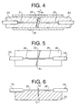
- Fig. 4 is a cross-sectional view showing the optical fiber wavelength filter.
- Optical fibers 21 and 22 are inserted into ceramic ferrules 23 and 24 and bonded therein to prepare a pair of ground ferrules with optical fibers. Then, a glass substrate filter 25 composed of a glass substrate and a multilayer dielectric film formed on the surface thereof is placed between the foregoing pair of ferrules 23 and 24 with optical fibers, and the optical axes of the ceramic ferrules 23 and 24 are aligned using an aligning sleeve 26 before securing them with an adhesive agent.
- This prior art has been posing a problem in that the use of the glass substrate filter 25, in which thickness t is normally a few hundred ⁇ m ( ⁇ 300 ⁇ m), causes transmitted light to be refracted by the glass substrate or mode field diffusion to take place. The optical axis of the refracted light is inevitably displaced from the central axis of the ferrules.
- the mechanical central axes of the ceramic ferrules with optical fibers are aligned by the inside diameter of the aligning sleeve and the misalignment of the optical axis of the transmitted light caused by the refraction can hardly be corrected.
- the results of the experiments carried out by the inventor have revealed that, when thickness t of the glass substrate filter is 300 ⁇ m, the measured value of the insertion loss is approximately 7 dB mainly due to the dislocated optical axis, or when the thickness is 500 ⁇ m, the insertion loss is approximately 9 dB. This means that it is difficult to control the insertion loss in this wavelength filter.
- a thermosetting adhesive agent is usually used in manufacturing the optical fiber wavelength filters employing the aforesaid aligning sleeves; this type of adhesive agent typically requires at least a few tens of minutes to completely harden.
- the US Patent No. 5,234,772 has disclosed a dielectric multilayer film filter and a manufacturing method for the same.
- the optical fiber wavelength filter employs a filter composed of a dielectric multilayer film formed on a fluorinated polyimide thin film (hereinafter referred to as "thin-film filter").
- the filter produced according to this process has an extremely thin wavelength filter owing to the use of the fluorinated polyimide thin film; hence, this filter is free from the deterioration in the optical properties resulting from the use of the thick glass substrate filter mentioned above.
- Figure 5 is a top plan view of an optical fiber wavelength filter employing the conventional thin-film filter
- Fig. 6 is a longitudinal sectional view of a wavelength filter employing the conventional thin-film filter.
- Optical fibers 35 and 36 are secured to a substrate 30 by an adhesive agent. Then, the optical fibers are cut and a groove 31 is formed across, then a thin-film filter 32 is inserted in the groove 31 and secured therein by an adhesive agent.
- the US Patent has also disclosed an example wherein a zirconia ferrule is used in place of the substrate 30, optical fibers being attached and bonded thereto, and the zirconia ferrule or a stainless flange is provided with a groove wherein the thin-film filter is disposed.
- the substrate 30, the substrate with optical fibers, the zirconia ferrule, or the like with the groove wherein the thin-film filter is disposed; it is not easy, however, to precisely form the groove having a width of about a few tens of ⁇ m.
- the variations in the machining dimension of the groove width directly affect the properties of the wavelength filter and lead to the variations in the optical properties such as insertion loss of the wavelength filter.
- the end surfaces of the optical fibers that are cut apart at the time of making the groove for holding the thin-film filter cannot be ground, so that the irregular reflection of light may take place on the connection end surfaces with consequent deterioration in optical properties.
- the conventional optical fiber wavelength filters have many problems in the manufacturing process or optical properties.
- the present invention has been made with a view toward solving the problems described above, and it is an object thereof to provide an optical fiber wavelength filter which is superior to the conventional ones described above in optical properties.
- Another object of the present invention is to provide a manufacturing method for the optical fiber wavelength filter.
- an optical fiber wavelength filter comprising a pair of ferrules, at least one of which is composed of a material transparent to a light ray containing a particular wavelength component, a pair of optical fibers which are supported by said ferrules and the distal end surfaces of which are grounded together with the end surfaces of said ferrules, a thin dielectric multilayer, film filter disposed between the ground distal end surfaces of said ferrules, and an adhesive agent which is cured by irradiating said dielectric multilayer film filter with a light ray containing said particular wavelength component and which is fixed between said ferrules.
- Said light ray containing said particular wavelength component is an ultraviolet ray
- said adhesive agent is an ultraviolet-curing resin adhesive agent
- at least one of said ferrules is a glass ferrule.
- Said thin multilayer film filter has a thickness of approximately a few tens of ⁇ m, and the exterior of said multilayer film filter lies within the joint surface of said ferrules when it is bonded.
- the distal ends of said ferrules are slant ground surfaces of 6 degrees or more.
- an optical fiber wavelength filter comprising the steps of preparing a pair of ferrules, at least one of which is composed of a material transparent to a light ray containing a particular wavelength component, bonding and securing optical fibers to said ferrules and grinding the distal end surfaces thereof, providing a thin multilayer film filter and an adhesive agent, which is hardened by a light ray containing said particular wavelength component, between the distal ends of said ferrules and performing optical axis alignment by an optical axis aligning support member which supports said ferrules and permits the adjustment of relative positions, and irradiating said adhesive agent between the distal ends of said pair of ferrules with a light ray containing said particular wavelength component from outside upon completion of said optical axis alignment so as to fix said pair of ferrules and said thin multilayer film filter into one piece.
- Said light ray containing said particular wavelength component is an ultraviolet ray
- said adhesive agent is an ultraviolet-curing resin adhesive agent
- at least one of said ferrules is a glass ferrule.
- Said pair of ferrules are the ferrules having substantially the same outside diameter and said optical axis aligning support member is a V-groove support member which provides a common V-groove surface to said pair of ferrules.
- a portion corresponding to the joining position of said ferrules supported by said V-groove support member is provided with a clearance groove.
- V-groove matched to the joint position of the ferrules supported by the V-groove support member is removed and a clearance groove is provided. This allows extra adhesive agent to be relieved, makes it easier to observe the joint condition, and permits ultraviolet rays to be irradiated sideways.
- Figure 1 is a longitudinal sectional view showing an embodiment of the optical fiber wavelength filter in accordance with the present invention.
- the optical fiber wavelength filter in accordance with this embodiment is constituted by: a pair of glass ferrules 1 and 2 with optical fibers 3 and 4 of optical fiber cables 5 and 6; a thin-film filter 9; an adhesive agent (not shown) which has been hardened by ultraviolet rays; hoods 7 and 8; and a protective pipe 10.
- the distal ends of the glass ferrules 1 and 2 have been ground with an angle of 6 degrees or more to minimize the feedback light attributable to Fresnel reflection at the boundary surface.
- the thin-film filter 9 may use the thin dielectric multilayer film filter manufactured by the method described above as the prior art.
- the filter may have any of the following wavelength properties: a short-wavelength type that passes light waves of short wavelengths, a long-wavelength type that passes those of long wavelengths, or a bandpass type that passes those of a particular wavelength.
- the hoods 7 and 8 are made of rubber or plastics to provide resilience.
- the hoods 7 and 8 function to secure the roots of the glass ferrules with the optical fibers with respect to the protective pipe 10 in order to safety house the optical fiber wavelength filter in the protective pipe 10; they do not function to align optical axes.
- These hoods 7 and 8 also serve to protect the ferrule connections of the optical fiber cables 5 and 6.
- the protective pipe 10 uses a stainless pipe; it may, however, use a resinous pipe.
- the optical fiber wavelength filter shown as the embodiment has an extremely simple structure, it provides high performance in which the insertion loss is 0.5 dB or less and the return loss is 55 dB or more.
- Figure 2 is a longitudinal sectional view illustrating the manufacturing process of the embodiment
- Fig. 3 is a cross-sectional view thereof.
- a pair of ferrules is prepared; at least one of them is made of a material transparent to a light ray that includes a particular wavelength component.
- the light ray which includes the particular wavelength component is an ultraviolet ray
- an ultraviolet-curing resin adhesive agent is used as the adhesive agent to make both glass ferrules 1 and 2 transparent to ultraviolet rays.
- the glass ferrules have the same outside diameter.
- optical fiber cables 5 and 6 are inserted in and bonded to the ferrules 1 and 2 in such a manner that the optical fibers 3 and 4 at the distal ends thereof are exposed so that they may be ground.
- the distal ends are ground with an angle.
- the ferrules with the optical fibers which have been ground are supported using a support member for aligning optical axes in order to align the optical axes of the optical fibers.
- a V-groove support member 13 that provides a V-groove surface common to the pair of ferrules 1 and 2 is used; V-groove surfaces 15A and 16A are made flush, while V-groove surfaces 15B and 16B are made flush.
- the ferrule 1 is supported by the V-groove surfaces 15A and 15B, while the ferrule 2 is supported by the V-groove surfaces 16A and 16B.
- the thin multilayer film filter 9 and ultraviolet-curing resin adhesive agents 11 and 12 are disposed between the ferrules 1 and 2, and the optical axes are aligned while lightly pushing them from above as indicated by the arrows.
- the distal ends of the optical fibers are pressed into contact while pushing the ferrules in the direction indicated by the arrows in Figs. 2 and 3, and one or both of the ferrules are turned to match the joint surfaces.
- the V-groove matched to the joint position of the ferrules 1 and 2 supported by the V-groove support member 13 is removed; instead, a clearance groove 14 is provided.
- a pair of adjustable stages with aligning V-grooves may be used instead of the aligning V-groove jig with the clearance groove 14 for relieving extra adhesive agent, and one or both of the stages may be three-dimensionally moved to achieve alignment with minimized insertion loss by making adjustment while measuring the properties of the optical fiber wavelength filter such as insertion loss by using an optical power meter.
- ultraviolet rays are irradiated from outside to expose the adhesive agents between the pair of ferrules 1 and 2 to the ultraviolet rays so as to instantly fix the pair of ferrules 1 and 2 and the thin-film filter 9 into one piece.
- the filter could be used as it is, or the hoods may be covered on both ferrules and housed in the protective pipe 10 as illustrated in Fig. 1.
- the distal ends of the ferrules have been ground with an angle; however, they may alternatively be ground at right angles. Even if ground surfaces of the ferrules may be spherical rather than plane, there should be no problem because the gap is filled with an adhesive agent for fixation.
- both ferrules are transparent to ultraviolet rays in the embodiment, it is not required that both ferrules be transparent; at least one of them needs to be transparent because all that is necessary is to let sufficient light reach the joint surface to cure the adhesive agent.
- the roots of the ferrules and the fiber cables may be wrapped with a heat-shrinkable tube and this assembly may be inserted and bonded in a protective pipe.
- the optical fiber wavelength filter in accordance with the present invention has a simple construction and it permits easier optical axis alignment and easier manufacture.
- the present invention makes it possible to provide a high-performance optical fiber wavelength filter at lower cost.
Landscapes
- Physics & Mathematics (AREA)
- General Physics & Mathematics (AREA)
- Optics & Photonics (AREA)
- Optical Couplings Of Light Guides (AREA)
- Light Guides In General And Applications Therefor (AREA)
- Mechanical Coupling Of Light Guides (AREA)
Applications Claiming Priority (2)
| Application Number | Priority Date | Filing Date | Title |
|---|---|---|---|
| JP12896398 | 1998-05-12 | ||
| JP10128963A JPH11326641A (ja) | 1998-05-12 | 1998-05-12 | 光ファイバ波長フィルタおよびその製造方法 |
Publications (3)
| Publication Number | Publication Date |
|---|---|
| EP0957379A2 true EP0957379A2 (de) | 1999-11-17 |
| EP0957379A3 EP0957379A3 (de) | 2003-01-15 |
| EP0957379B1 EP0957379B1 (de) | 2005-03-09 |
Family
ID=14997753
Family Applications (1)
| Application Number | Title | Priority Date | Filing Date |
|---|---|---|---|
| EP99104149A Expired - Lifetime EP0957379B1 (de) | 1998-05-12 | 1999-03-02 | Faseroptischer Wellenlängenfilter und Verfahren zu dessen Herstellung |
Country Status (4)
| Country | Link |
|---|---|
| US (1) | US6280099B1 (de) |
| EP (1) | EP0957379B1 (de) |
| JP (1) | JPH11326641A (de) |
| DE (1) | DE69924051T2 (de) |
Cited By (3)
| Publication number | Priority date | Publication date | Assignee | Title |
|---|---|---|---|---|
| US9442005B2 (en) | 2014-07-30 | 2016-09-13 | Corning Optical Communications LLC | Non-contact methods of measuring insertion loss in optical fiber connectors |
| US10473860B1 (en) | 2018-05-11 | 2019-11-12 | Alliance Fiber Optic Products, Inc. | Compact devices for multiplexing applications |
| US12326602B2 (en) | 2020-07-23 | 2025-06-10 | Opticis Co., Ltd. | Optical connector supporting bidirectional communication |
Families Citing this family (21)
| Publication number | Priority date | Publication date | Assignee | Title |
|---|---|---|---|---|
| EP1843495A1 (de) * | 1997-02-14 | 2007-10-10 | Nippon Telegraph and Telephone Corporation | Tellurit-Glas, optischer Verstärker und Lichtquelle |
| US6434283B2 (en) * | 1997-03-13 | 2002-08-13 | Litton Systems, Inc. | In-line fiber-optic polarizer |
| US6623174B2 (en) * | 2000-10-12 | 2003-09-23 | Tyco Electronics Corporation | Optical connector |
| KR100401805B1 (ko) * | 2001-04-09 | 2003-10-17 | (주) 래트론 | 가변형 광 필터 |
| TW509781B (en) * | 2001-05-10 | 2002-11-11 | Uconn Technology Inc | Measurement method and device of the slanting surface angle of optical device |
| DE10201127C2 (de) * | 2002-01-09 | 2003-11-20 | Infineon Technologies Ag | Anordnung zum Ein- und/oder Auskoppeln optischer Signale mindestens eines optischen Datenkanals in bzw. aus einem Lichtwellenleiter |
| US20030142923A1 (en) * | 2002-01-30 | 2003-07-31 | Chiaro Networks Ltd. | Fiberoptic array |
| US6813416B2 (en) * | 2002-02-20 | 2004-11-02 | Lightwaves 2020, Inc. | Miniature fiberoptic filter and method of manufacture therefor |
| US20040223682A1 (en) * | 2003-05-06 | 2004-11-11 | Yi Ding | Hybrid optical circuits with thin film filters |
| US7198549B2 (en) * | 2004-06-16 | 2007-04-03 | Cabot Microelectronics Corporation | Continuous contour polishing of a multi-material surface |
| KR20060055606A (ko) * | 2004-11-18 | 2006-05-24 | 한국전자통신연구원 | 온도 무의존 외부 공진 레이저 |
| EP2277272A1 (de) * | 2008-04-21 | 2011-01-26 | Oplink Communications, Inc | Fasernetzwerküberwachung |
| US8137001B2 (en) * | 2009-11-02 | 2012-03-20 | Harris Corporation | Repeatable optical waveguide interconnection including an index matching elastomeric solid layer and related methods |
| US8195016B2 (en) * | 2009-11-02 | 2012-06-05 | Harris Corporation | Optical fiber switch including an index matching elastomeric solid layer and related methods |
| US8175426B2 (en) * | 2009-11-02 | 2012-05-08 | Harris Corporation | Optical fiber switch including an index matching elastomeric solid layer providing core and cladding index of refraction matching and related methods |
| CN103217745A (zh) * | 2012-01-19 | 2013-07-24 | 王辉文 | 用于ftth中pon链路监测的光滤波器及制造工艺 |
| CN103676014B (zh) * | 2012-09-05 | 2015-09-09 | 武汉隽龙科技有限公司 | 具有光滤波功能的sc型光纤适配器制造工艺 |
| US9651737B2 (en) | 2015-09-24 | 2017-05-16 | Harris Corporation | Optical communication system having filter with index selectable material and related methods |
| JP6597439B2 (ja) * | 2016-03-24 | 2019-10-30 | 住友電気工業株式会社 | 光コネクタフェルール、光コネクタ及び光結合構造 |
| KR101953281B1 (ko) * | 2016-07-19 | 2019-02-28 | (주)파이버피아 | 설치 및 환경에 의한 오차가 없는 광섬유 센서를 이용한 센싱시스템 |
| EP3519873A1 (de) * | 2016-09-27 | 2019-08-07 | AFL Telecommunications LLC | Faseroptische adapter und verbinder mit wellenlängenfilterungskomponenten |
Family Cites Families (7)
| Publication number | Priority date | Publication date | Assignee | Title |
|---|---|---|---|---|
| US5208886A (en) * | 1990-01-17 | 1993-05-04 | At&T Bell Laboratories | Methods of making an optical fiber filter |
| EP0442801B1 (de) * | 1990-02-13 | 1995-05-10 | Nippon Telegraph And Telephone Corporation | Herstellungsverfahren von dielektrischen Vielschichtenfiltern |
| JP3099167B2 (ja) * | 1994-06-14 | 2000-10-16 | セイコーインスツルメンツ株式会社 | 光学フィルタ内蔵光通信用部品 |
| IT1271222B (it) | 1994-09-28 | 1997-05-27 | Sirti Spa | Filtro ottico per telecomunicazioni |
| US5892582A (en) * | 1996-10-18 | 1999-04-06 | Micron Optics, Inc. | Fabry Perot/fiber Bragg grating multi-wavelength reference |
| DE69733202D1 (de) * | 1996-10-18 | 2005-06-09 | Micron Optics Inc | Eine multiwellenlängenreferenz |
| EP0844506B1 (de) * | 1996-11-21 | 2003-08-13 | Sumitomo Electric Industries, Ltd. | Optischer Schalter und Schaltverfahren |
-
1998
- 1998-05-12 JP JP10128963A patent/JPH11326641A/ja active Pending
- 1998-07-31 US US09/127,760 patent/US6280099B1/en not_active Expired - Fee Related
-
1999
- 1999-03-02 EP EP99104149A patent/EP0957379B1/de not_active Expired - Lifetime
- 1999-03-02 DE DE69924051T patent/DE69924051T2/de not_active Expired - Fee Related
Cited By (5)
| Publication number | Priority date | Publication date | Assignee | Title |
|---|---|---|---|---|
| US9442005B2 (en) | 2014-07-30 | 2016-09-13 | Corning Optical Communications LLC | Non-contact methods of measuring insertion loss in optical fiber connectors |
| US10072972B2 (en) | 2014-07-30 | 2018-09-11 | Corning Optical Communications LLC | Non-contact methods of measuring insertion loss in optical fiber connectors |
| US10473860B1 (en) | 2018-05-11 | 2019-11-12 | Alliance Fiber Optic Products, Inc. | Compact devices for multiplexing applications |
| WO2019217117A1 (en) * | 2018-05-11 | 2019-11-14 | Alliance Fiber Optic Products, Inc. | Compact devices for wavelength-division multiplexing applications |
| US12326602B2 (en) | 2020-07-23 | 2025-06-10 | Opticis Co., Ltd. | Optical connector supporting bidirectional communication |
Also Published As
| Publication number | Publication date |
|---|---|
| EP0957379B1 (de) | 2005-03-09 |
| DE69924051T2 (de) | 2006-05-11 |
| US6280099B1 (en) | 2001-08-28 |
| EP0957379A3 (de) | 2003-01-15 |
| DE69924051D1 (de) | 2005-04-14 |
| JPH11326641A (ja) | 1999-11-26 |
Similar Documents
| Publication | Publication Date | Title |
|---|---|---|
| EP0957379B1 (de) | Faseroptischer Wellenlängenfilter und Verfahren zu dessen Herstellung | |
| CA2569263C (en) | Optical ferrule | |
| US5668905A (en) | Optical fiber ferrule assembly having angular index showing polarization plane | |
| US6324323B1 (en) | Adhesive-free lens-attached optical fibers to optical waveguide packaging system | |
| US10816735B2 (en) | Lensed connector ferrule assemblies and methods of fabricating the same | |
| JPH0552925B2 (de) | ||
| EP0399684B1 (de) | Laser-Modul mit optischer Faser und Methode zu seiner Herstellung | |
| EP2549313B1 (de) | Presshülse mit integrierter Faserausrichtung | |
| WO2001097589A2 (en) | Three-port filter and method of manufacture | |
| JPH11326641A5 (de) | ||
| JPH08286069A (ja) | 光ファイバ・アレー/光集積回路接続アッセンブリと、接続アッセンブリを保護するためのエンクロージャ | |
| US6934087B1 (en) | Fiber optic collimator and collimator array | |
| US7046877B2 (en) | Optical module | |
| CA2296471A1 (en) | Planar optical device connector and method for making same | |
| JP4012537B2 (ja) | 光モジュール及びその作製方法 | |
| JP3112255B2 (ja) | 光ファイバ用接続部材の製造方法 | |
| JPH06294911A (ja) | 光固定減衰器およびその製造方法 | |
| JPH08286070A (ja) | 光ファイバ・アレー/光集積回路接続アッセンブリで使用される光ファイバ・アレーを作るための方法 | |
| US20240255703A1 (en) | Optical connector and manufacturing method thereof | |
| JP3329951B2 (ja) | 光学素子と接続用光部品の接続構造 | |
| JP3132855B2 (ja) | 光結合器およびその結合方法 | |
| CA1241412A (en) | Method of splicing fiber optic cable | |
| AU729723C (en) | Planar optical device connector and method for making same | |
| Anderson et al. | Report: lightwave splicing and connector technology | |
| EP0274199A2 (de) | Kupplung zwischen optischen Fasern und optischen Wellenleitern |
Legal Events
| Date | Code | Title | Description |
|---|---|---|---|
| PUAI | Public reference made under article 153(3) epc to a published international application that has entered the european phase |
Free format text: ORIGINAL CODE: 0009012 |
|
| AK | Designated contracting states |
Kind code of ref document: A2 Designated state(s): AT BE CH CY DE DK ES FI FR GB GR IE IT LI LU MC NL PT SE |
|
| AX | Request for extension of the european patent |
Free format text: AL;LT;LV;MK;RO;SI |
|
| PUAL | Search report despatched |
Free format text: ORIGINAL CODE: 0009013 |
|
| AK | Designated contracting states |
Kind code of ref document: A3 Designated state(s): AT BE CH CY DE DK ES FI FR GB GR IE IT LI LU MC NL PT SE |
|
| AX | Request for extension of the european patent |
Free format text: AL;LT;LV;MK;RO;SI |
|
| 17P | Request for examination filed |
Effective date: 20030405 |
|
| AKX | Designation fees paid |
Designated state(s): DE GB |
|
| 17Q | First examination report despatched |
Effective date: 20031203 |
|
| GRAP | Despatch of communication of intention to grant a patent |
Free format text: ORIGINAL CODE: EPIDOSNIGR1 |
|
| GRAS | Grant fee paid |
Free format text: ORIGINAL CODE: EPIDOSNIGR3 |
|
| GRAA | (expected) grant |
Free format text: ORIGINAL CODE: 0009210 |
|
| AK | Designated contracting states |
Kind code of ref document: B1 Designated state(s): DE GB |
|
| REG | Reference to a national code |
Ref country code: GB Ref legal event code: FG4D |
|
| REG | Reference to a national code |
Ref country code: IE Ref legal event code: FG4D |
|
| REF | Corresponds to: |
Ref document number: 69924051 Country of ref document: DE Date of ref document: 20050414 Kind code of ref document: P |
|
| PLBE | No opposition filed within time limit |
Free format text: ORIGINAL CODE: 0009261 |
|
| STAA | Information on the status of an ep patent application or granted ep patent |
Free format text: STATUS: NO OPPOSITION FILED WITHIN TIME LIMIT |
|
| 26N | No opposition filed |
Effective date: 20051212 |
|
| PGFP | Annual fee paid to national office [announced via postgrant information from national office to epo] |
Ref country code: GB Payment date: 20070322 Year of fee payment: 9 |
|
| PGFP | Annual fee paid to national office [announced via postgrant information from national office to epo] |
Ref country code: DE Payment date: 20070331 Year of fee payment: 9 |
|
| GBPC | Gb: european patent ceased through non-payment of renewal fee |
Effective date: 20080302 |
|
| PG25 | Lapsed in a contracting state [announced via postgrant information from national office to epo] |
Ref country code: DE Free format text: LAPSE BECAUSE OF NON-PAYMENT OF DUE FEES Effective date: 20081001 |
|
| PG25 | Lapsed in a contracting state [announced via postgrant information from national office to epo] |
Ref country code: GB Free format text: LAPSE BECAUSE OF NON-PAYMENT OF DUE FEES Effective date: 20080302 |