EP0956499B2 - Détecteur de fibres et de matériaux étrangers basé sur une mesure d'absorption de la lumière et procédé de détection correspondant - Google Patents
Détecteur de fibres et de matériaux étrangers basé sur une mesure d'absorption de la lumière et procédé de détection correspondant Download PDFInfo
- Publication number
- EP0956499B2 EP0956499B2 EP98901263A EP98901263A EP0956499B2 EP 0956499 B2 EP0956499 B2 EP 0956499B2 EP 98901263 A EP98901263 A EP 98901263A EP 98901263 A EP98901263 A EP 98901263A EP 0956499 B2 EP0956499 B2 EP 0956499B2
- Authority
- EP
- European Patent Office
- Prior art keywords
- light
- measurement
- measurement volume
- detector
- textile material
- Prior art date
- Legal status (The legal status is an assumption and is not a legal conclusion. Google has not performed a legal analysis and makes no representation as to the accuracy of the status listed.)
- Expired - Lifetime
Links
Images

Classifications
-
- G—PHYSICS
- G01—MEASURING; TESTING
- G01N—INVESTIGATING OR ANALYSING MATERIALS BY DETERMINING THEIR CHEMICAL OR PHYSICAL PROPERTIES
- G01N21/00—Investigating or analysing materials by the use of optical means, i.e. using sub-millimetre waves, infrared, visible or ultraviolet light
- G01N21/84—Systems specially adapted for particular applications
- G01N21/88—Investigating the presence of flaws or contamination
- G01N21/89—Investigating the presence of flaws or contamination in moving material, e.g. running paper or textiles
- G01N21/8914—Investigating the presence of flaws or contamination in moving material, e.g. running paper or textiles characterised by the material examined
- G01N21/8915—Investigating the presence of flaws or contamination in moving material, e.g. running paper or textiles characterised by the material examined non-woven textile material
-
- G—PHYSICS
- G01—MEASURING; TESTING
- G01B—MEASURING LENGTH, THICKNESS OR SIMILAR LINEAR DIMENSIONS; MEASURING ANGLES; MEASURING AREAS; MEASURING IRREGULARITIES OF SURFACES OR CONTOURS
- G01B11/00—Measuring arrangements characterised by the use of optical techniques
- G01B11/08—Measuring arrangements characterised by the use of optical techniques for measuring diameters
- G01B11/10—Measuring arrangements characterised by the use of optical techniques for measuring diameters of objects while moving
- G01B11/105—Measuring arrangements characterised by the use of optical techniques for measuring diameters of objects while moving using photoelectric detection means
Definitions
- a detector of foreign fibres can be used for the detection of foreign fibres and foreign materials in the textile industry, for example in yarns, slivers and unformed fibre bands on, for example (though not exclusively), weaving machines, ring spinning machines, open-end spinning machines, air-jet spinning machines or chemical spinning machines, bobbin winding machines, doubling machines, cards, drawing benches, combing machines, bobbin frames, texturing machines, ...
- the principle based on contrast measurement against a background has the drawbacks that the background has to be matched to the yarn and also that this principle is unable to eliminate the influence of diameter variations of the measurement object itself to a sufficient extent.
- This drawback also applies to the principle according to which the reflection on the measurement object is normalized using diameter information. As a result, the sensitivity of these methods to foreign fibres and foreign materials is lower than desired.
- IEP-A-0 652 432 describes a detector and detection method for foreign fibres.
- the detector has three compartments: a first one in which a light source is placed, a second one through which a yarn runs and a third one, in which a sensor unit is placed.
- the sensor unit is sensitive to particular wavelengths of light. It comprises two sensors having different spectral responses. The sensors receive light directly reflected from the yarn. Other light is directed by a mirror away from the sensor.
- US-A-4 853 776 describes a fabric inspection method and apparatus for detecting flaws. It comprises a room (2) and a transporter for fabric. Strobe lights and image pick-up elements are arranged on opposite sides of the fabric in transportation. The strobe lights on each side are operated in turn to illuminate the fabric. The pick-up elements on the other side pick up transmissions through the fabric. An image processing unit is provided to detect flaws.
- the object of the detector according to the present invention is to provide a solution to the abovementioned drawbacks.
- the present invention provides a method according to claim 1 and a defector according to claim 13.
- the detection method for detecting foreign fibres or foreign materials according to the invention is based on measuring the absorption of light which fills a measurement volume within which a measurement object is situated. Said absorption of light is measured without separately driving light sources for reflection and transmission, and without separately detecting signals representative for reflection and transmission.
- the spectrum of the light which is used for this purpose is selected in such a way that the measurement object does not absorb this light to a significant extent. Use is made of the fact that in that case foreign fibres and foreign materials will have a greater absorption coefficient for the spectrum of the light used than the measurement object itself.
- the method is preferably carried out by introducing light into the measurement volume, in which the measurement object to be examined is situated, via at least one light source. Photodetection takes place around this measurement volume, with the result that all the light, or a representative sample of the light, inside the measurement volume is measured and converted into a proportional electrical signal. Comparison of this signal with a signal measured when the measurement volume was empty provides the absorption in the measurement volume, and interpretation of this provides the level of contamination of the measurement object.
- the essential feature of the principle is the detection of all the light in the measurement volume, or of a representative sample thereof which is taken uniformly over the entire measurement volume. Furthermore, there are no specific conditions placed on the illumination, detection and measurement volume, in contrast to the principles currently used for the detection of foreign fibres and foreign materials, the correct functioning of which depends on the selection of the background, the setting of the background illumination or on an auxiliary signal for normalization.
- the measurement volume contains a measurement object which is contaminated with a foreign fibre or foreign material
- not all the light incident on the measurement object is then returned into the measurement volume.
- the light which is incident on the foreign fibre or the foreign material is partially absorbed thereby and the quantity of light detected is considerably less.
- the resulting electrical signal is significantly less than the electrical signal measured when the measurement volume was empty or with an uncontaminated measurement object.
- the quantity of light in the measurement volume will be determined by the dimensions and absorption of the measurement object. If the dimensions do not change, the measurement signal can still always be used as a measure of the contamination.
- the absolute value of the light detected can be used to derive an absolute measure of the absorption of the light employed by the measurement object.
- the relative absorption can be derived by comparison with an uncontaminated measurement object.
- This evaluation can lead to assigning a contamination index in an automated manner to the measurement object, by associating a contamination index with each absorption.
- the electrical signal can be processed further in a conventional manner by means of analog or digital circuits or using programmable digital signal processing or microprocessor circuits. It is thus possible to take into account the amplitude and the length of the deviation, for example in order to decide whether it is necessary to interrupt the movement of the measurement object or the processing which the measurement object is undergoing, in order to remove the deviating parts from the measurement object, or for statistical characterization of the measurement object. Processing and using the signals in this way is usual both for detectors of foreign fibres which are based on other principles and for measurement equipment based on diameter or mass measurements which is known from the prior art.
- the spectrum of the measurement light has a considerable influence on the types of foreign fibres and foreign materials which can be detected using the detector according to the invention. This is linked to the spectral absorption properties of these contaminating materials.
- Some foreign fibres and foreign materials in the measurement object can be perceived visually as a change in intensity or a discoloration. Extensive tests have demonstrated that this visible contamination can best be detected using yellow or green measurement light.
- the light source used in the present invention does not necessarily have to be a light-emitting diode, also known as LED, but may also be an incandescent lamp or an arc lamp which fills the measurement volume with light, either directly or indirectly, via one or more optical conductors.
- the light source it is possible to use, for example, electroluminescent materials.
- a layer of a material of this kind is applied to a substrate.
- This substrate may take the form of a cylinder.
- the light source is preferably disposed in such a way that the space inside the measurement volume is illuminated uniformly.
- the measurement light emanating from the light source may optionally be intensity-modulated.
- intensity modulation of the measurement light at a specific frequency it is possible to distinguish it from ambient light and thus to suppress the latter effectively.
- One or more photosensitive elements can be used for the photodetection. Their number is not essential, but it is necessary that there is an arrangement which allows all the light in the measurement volume, or a representative sample thereof, to be measured.
- the photosensitive elements used must be sufficiently sensitive to the spectrum of the measurement light emitted by the light source.
- the photodetectors may, for example, be silicon photodiodes, but the invention is not limited to such detectors. These photodiodes are suitable for the detection of light in the visible spectrum and the near infrared (typically 400 to 1100 nm). Other photodetectors are known to the person skilled in the art for both shorter wavelengths (UV) and for longer wavelengths (IR), such as for example germanium or InGaAs photodiodes.
- Photodiodes are mostly constructed as discrete components.
- the current state of technology also allows photodetectors to be applied to a substrate in the form of an active layer. It is conceivable that this substrate may adopt a form which adjoins the measurement volume or forms the measurement volume, such as for example, although not exclusively, the form of a cylinder.
- This method is a perfect addition to the approach using an electroluminescent light source, which as stated above is also applied to a substrate in the form of an active layer.
- the shape of the measurement volume should allow all the light present, or a representative sample thereof to be measured by photodetection.
- This shape may, for example, be a sphere or a cylinder.
- One or more openings are provided in the measurement volume in order to allow the measurement object to enter and leave the measurement volume. According to a possible embodiment, this opening takes the form of a slot. On the other hand, it is possible to provide two openings in a sphere or cylinder, respectively for the entry and exit of the measurement object.
- the boundary of the measurement volume is resistant to the friction caused by the measurement object. It is preferably dirt-repellent and easy to clean. It is made from a material which is transparent to the measurement light or transmits the latter if the light source(s) and/or detector(s) are placed outside the measurement volume.
- the measurement volume may be positioned anywhere in the normal path of the measurement object, either as an extra component or to replace or supplement components which are already present in the path.
- illumination which comprises a plurality of colours or wavelengths or bands of wavelengths.
- the combination can be optimized for the detection of specific contaminants.
- the light from one or more broad-band light sources such as for example an arc lamp or incandescent lamp, the spectral distribution of which is optionally adapted to the requirements by active or passive optical filtering.
- the detection can be carried out by measuring the total resulting quantity of light in the measurement volume, or a representative, uniform sample thereof. This is used to obtain a total weighted absorption for the colours or wavelengths or bands of wavelengths used.
- the absorption can be measured separately for the various colours or wavelengths or bands of wavelengths.
- the light sources or groups of light sources which emit a different colour or wavelength or band of wavelengths can be switched on and off sequentially or can be intensity-modulated at a different frequency.
- the signals can be separated from one another using synchronous detection or electronic filtering.
- the only essential factor is that all the light present in the measurement volume, or at least a representative sample thereof, is detected for each colour or wavelength or band of wavelengths.
- Figure 1 and Figure 2 each show a detector 1 according to the invention. They each comprise at least one light source 2 and one or more photodetectors 3 which enclose a measurement volume 4. Both the light source 2 and the photodetectors 3 are situated around the measurement volume 4, through which a measurement object 5 to be examined is passing.
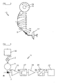
- Figure 3 shows a diagrammatic illustration of the path 13 of the yarn in an open-end spinning machine.
- a detector 1 for detecting foreign fibres and foreign materials in a measurement object 5, which is a yarn spun on an open-end spinning machine.
- a person skilled in the art is able to modify this embodiment for other applications, such as other types of spinning machines, bobbin winding machines, doubling machines, cards, combing machines, texturing machines, weaving machines, ...
- Known detectors 16 are usually placed on an open-end spinning machine in the path of the yarn between the navel 14 and the bobbin 15.
- the yarn 5 is wound onto the bobbin 15 from the navel 14 via drive and guide rolls 19.
- known detectors 16 in the path of the yarn are always provided with some form of slot, along which the yarn 5 is introduced into the measurement slot of the detector 16.
- Supports 20 ensure that the position of the yarn 5 in a detector 16 is stable.
- detectors of foreign fibres are integrated with the equipment for measuring diameter or mass. The detection method described here can likewise be carried out in this way.
- a significant problem is that there is not sufficient space available for this on every type or model of open-end spinning machine.
- a detector 1 based on absorption measurement can also be placed on open-end spinning machines between the navel 14 and the rotor 17 itself, where the so-called “spinning tube” 18, a tubular element which is essential to the open-end spinning process, forms a channel which guides the yarn outwards from the rotor 17.
- the tubular shape of the spinning tube 18 corresponds extremely well to the requirements of an ideal measurement volume.
- the detector 1 is placed on the spinning tube 18 or integrated therewith. This has a number of advantages:
- Spinning process demands such as a specific finish
- the components of the detector 1 are arranged on the outer circumference of the spinning tube 18. This means that the material forming the spinning tube 18 must be transparent or light-transmitting for the measurement light emanating from the light source 2. There is sufficient space and capacity to supplement and adapt the spinning tube 18 for the mounting of a detector 1.
- the spinning tube 18 is designed with a transparent wall 6.
- a light source 2 which comprises two light-transmitting electrodes 7 and an active layer 8.
- the active layer 8 consists, for example, of an electroluminescent material. This material is transparent or light-transmitting to the light emitted.
- a light-sensitive layer 3 which comprises two transparent electrodes 9, between which is situated a photodetection layer 10.
- the photodetection layer 10 preferably comprises a photodiode produced from amorphous silicon.
- the structure of the layers is made clearer by an enlarged detail 33 from detector 1 in Figure 1 .
- this arrangement fulfils the requirement of detecting all the light in the measurement volume 4.
- silicon photodiodes which are produced from monocrystalline silicon are used as photodetectors 3. It is ensured that the circumference of the measurement volume 4 is surrounded as completely as possible by the various silicon photodiodes.
- These photodiodes are selected in such a way that they are sensitive to the light which is emitted by the light source 2 used in the detector 1.
- a non-absorbing optical diffuser 12 is placed between the measurement volume 4 and the photodetectors 3.
- a non-absorbing, optically diffusing material is used for the wall of the spinning tube 18. All the light in the measurement volume 4 is ultimately incident on the diffuser 12. The spatial properties of that light are averaged out statistically in the diffuser 12. Some of this light is incident on the photodetectors 3, via the diffuser 12. In this way, a sample of all the light in the measurement volume 4 is measured, and the sample is taken uniformly over the entire measurement volume 4, with the result that this second preferred embodiment satisfies the requirements. In this way, the effect of the non-sensitive locations between the photodetectors 3, caused by the planar design of these photodetectors 3 and of the light sources 2, is eliminated.
- LEDs Light-emitting diodes
- one LED is sufficient for the detector 1 to function, but the greater quantity of light introduced into the measurement volume 4 by a plurality of LEDs provides a greater electro-optical signal-noise ratio.
- the light sources 2 are placed between the photodetectors 3 and illuminate the measurement volume 4 through the diffuser 12.
- Yellow LEDs are preferably used, owing to their high efficiency together with their absorption by most coloured foreign fibres and foreign materials.
- the electro-optical components of the detector 1 can be arranged on the spinning tube 18 in various ways.
- a first possibility is to attach the light sources 2 and the photodetectors 3 directly on the circumference.
- Another possibility is first to apply the components to a support, which is in turn attached to the outer wall of the spinning tube 18.
- Control circuit 22 is used to send a current 23 through the light source 2. As a result, the light source 2 emits light into the measurement volume 4.
- the signal current 24 from the photodetectors 3 is amplified with the aid of an amplifier 25.
- the amplified signal 26 is proportional to the absorption measured.
- the variations in the amplified signal 26 are amplified, via a high-pass filter 27, in an AC voltage amplifier 28.
- the output signal 29 from the AC voltage amplifier 28 is proportional to the variation in the absorption.
- This output signal 29 from the AC voltage amplifier 28 is fed to an analog-to-digital converter 30.
- the data 31 from the analog-to-digital converter 30 are processed further by a programmable digital computer 32.
Landscapes
- Engineering & Computer Science (AREA)
- Textile Engineering (AREA)
- Physics & Mathematics (AREA)
- Health & Medical Sciences (AREA)
- Life Sciences & Earth Sciences (AREA)
- Chemical & Material Sciences (AREA)
- Analytical Chemistry (AREA)
- Biochemistry (AREA)
- General Health & Medical Sciences (AREA)
- General Physics & Mathematics (AREA)
- Immunology (AREA)
- Pathology (AREA)
- Investigating Materials By The Use Of Optical Means Adapted For Particular Applications (AREA)
- Investigating Or Analysing Materials By Optical Means (AREA)
- Treatment Of Fiber Materials (AREA)
Claims (31)
- Procédé pour la détection de matières étrangères dans un matériau textile (5) situé dans un volume de mesure (4), le volume de mesure étant délimité par une paroi (6) entourant le matériau textile à l'exception d'une ou plusieurs ouvertures, comprenant les étapes consistant à :éclairer le matériau textile (5) à l'intérieur du volume de mesure (4) avec une lumière de mesure ayant une ou plusieurs longueurs d'onde en utilisant au moins une source de lumière, la ou les plusieurs longueurs d'onde de lumière étant sélectionnées afin qu'une matière étrangère et un matériau textile aient des absorptions spécifiques différentes de la lumière de mesure ;détecter au moins un échantillon représentatif de la lumière de mesure présente à l'intérieur du volume de mesure (4) prélevé dans le volume de mesure tout entier en utilisant un ou plusieurs photodétecteurs, au moins une source de lumière et le ou les plusieurs photodétecteurs étant positionnés à l'extérieur et autour du volume de mesure (4), le photodétecteur entourant complètement le volume de mesure ou la pluralité de photodétecteurs entourant le volume de mesure aussi complètement que possible, le volume de mesure étant éclairé uniformément par l'au moins une source de lumière ou un diffuseur étant installé entre le volume de mesure et le ou les plusieurs photodétecteurs ou un matériau diffusant optiquement est utilisé pour la paroi (6), le ou les plusieurs photodétecteurs produisant un premier signal électrique (24) en fonction de la lumière de mesure détectée durant l'étape de détection quand le matériau textile à détecter est présent dans le volume de mesure (4) ;obtenir à partir du premier signal électrique (24) une valeur d'absorption de l'absorption par le matériau textile (5) de la lumière de mesure, en comparant le premier signal électrique (24) à un second signal électrique déterminé en fonction de la lumière de mesure détectée dans le volume de mesure (4) lorsqu'aucun matériau textile ni matériau textile non contaminé n'étaient présents dans le volume de mesure (4) ; etdéterminer à partir de cette valeur d'absorption si une matière étrangère est présente dans le matériau textile (5).
- Procédé selon la revendication 1, caractérisé en ce que des sources de lumière pour la réflexion et la transmission ne sont pas commandées séparément, et des réflexions de l'arrière-plan et du matériau textile (5) ne sont pas nécessairement accordées.
- Procédé selon la revendication 1 ou 2, caractérisé en ce que la paroi (6) est une paroi perméable à la lumière.
- Procédé selon l'une quelconque des revendications 1 à 3, caractérisé en ce que le spectre de la lumière de mesure est choisi de façon à ce que le coefficient d'absorption du matériau textile (5) de cette lumière soit inférieur au coefficient d'absorption d'une matière étrangère.
- Procédé selon l'une quelconque des revendications 1 à 3, caractérisé en ce que le spectre de la lumière de mesure est choisi de façon à ce que le matériau textile (5) n'absorbe pas cette lumière de façon significative.
- Procédé selon l'une quelconque des revendications précédentes, caractérisé en ce qu'il comprend aussi les étapes suivantes :- le premier signal électrique (24) produit par transformation de la lumière détectée est un signal électrique proportionnel (24),- l'interprétation de cette valeur d'absorption donne le niveau de contamination par des matières étrangères.
- Procédé selon l'une quelconque des revendications précédentes, caractérisé en ce que la lumière de mesure a une pluralité de longueurs d'onde ou plusieurs largeurs de bande, les photodétecteurs détectent à différentes longueurs d'onde ou largeurs de bande et dans l'étape d'obtention, une valeur pour une absorption pondérée de la pluralité de longueurs d'onde ou de plusieurs largeurs de bande de la lumière est obtenue pour les longueurs d'onde utilisées.
- Procédé selon l'une quelconque des revendications 1 à 6, caractérisé en ce que la lumière qui est introduite dans le volume de mesure (4) est une lumière qui comporte plus d'une couleur ou longueur d'onde ou bande de longueurs d'onde, et la valeur de l'absorption est obtenue séparément pour chaque couleur ou longueur d'onde ou bande de longueurs d'onde.
- Procédé selon l'une des revendications 6 à 8, caractérisé en ce qu'un indice de contamination est associé au niveau de contamination.
- Procédé selon l'une des revendications précédentes, utilisé pendant que le matériau textile (5) est en mouvement ou en cours de traitement, caractérisé en ce que le procédé comprend de plus une étape qui arrête le mouvement ou le traitement quand une matière étrangère est détectée dans le matériau textile (5).
- Procédé selon l'une quelconque des revendications 1 à 10, caractérisé en ce que le volume de mesure est un cylindre, une sphère, un tube ou une fente.
- Procédé selon l'une quelconque des revendications 1 à 11, dans lequel la paroi (6) est résistante au frottement provoqué par le mouvement du matériau textile dans le volume de mesure (4).
- Détecteur (1) pour détecter des matières étrangères dans un matériau textile (5) qui est situé dans un volume de mesure (4), le détecteur comprenant :au moins une source de lumière (2) pour éclairer le matériau textile (5) dans le volume de mesure (4) avec une lumière de mesure ayant une ou plusieurs longueurs d'onde,un ou plusieurs photodétecteurs (3) qui transforment une lumière de mesure dans le volume de mesure (4) en un premier signal électrique (24), lorsque le matériau textile à détecter est présent dans le volume de mesure (4) etune unité de traitement de signal (21), caractérisé par :le volume de mesure étant délimité par une paroi (6) entourant le matériau textile à l'exception d'une ou plusieurs ouvertures ;la ou les plusieurs longueurs d'onde de lumière étant sélectionnées afin qu'une matière étrangère et un matériau textile aient des absorptions spécifiques différentes de la lumière de mesure ;au moins une source de lumière et le ou les plusieurs photodétecteurs (3) étant positionnés à l'extérieur et autour du volume de mesure (4) de telle manière que, de même que la forme du volume de mesure soit telle que le ou les plusieurs photodétecteurs détectent au moins un échantillon représentatif de la lumière de mesure présente dans le volume de mesure (4) comme prélevé dans le volume de mesure tout entier (4), le photodétecteur entourant complètement le volume de mesure ou la pluralité de photodétecteurs entourant le volume de mesure aussi complètement que possible, le volume de mesure étant éclairé uniformément par l'au moins une source de lumière ou un diffuseur étant installé entre le volume de mesure et le ou les plusieurs photodétecteurs ; ou un matériau diffusant optiquement est utilisé pour la paroi (6) ; et l'unité de traitement de signal étant conçue pour déterminer s'il y a des matières étrangères présentes dans le matériau textile (5) sur la base d'une valeur d'absorption obtenue par comparaison entre le premier signal électrique (24) et un second signal électrique déterminé en fonction de la lumière de mesure détectée dans le volume de mesure (4) lorsqu'aucun matériau textile ni matériau textile non contaminé n'étaient présents dans le volume de mesure (4).
- Détecteur (1) selon la revendication 13, caractérisé en ce que pour le spectre de la lumière de mesure le coefficient d'absorption du matériau textile (5) est inférieur au coefficient d'absorption d'une matière étrangère.
- Détecteur (1) selon la revendication 13 ou 14, caractérisé en ce que le spectre de la lumière de mesure n'est pas absorbé par le matériau textile (5) de façon significative.
- Détecteur (1) selon l'une quelconque des revendications 13 à 15, caractérisé en ce que la source de lumière (2) est sélectionnée parmi une LED, une lampe incandescente ou une lampe à arc.
- Détecteur (1) selon l'une quelconque des revendications 13 à 16, caractérisé en ce que la source de lumière (2) est une couche électroluminescente.
- Détecteur (1) selon une des revendications 13 à 17, caractérisé en ce que la source de lumière (2) émet une lumière jaune ou verte.
- Détecteur (1) selon une des revendications 13 à 18, caractérisé en ce que le ou les plusieurs photodétecteurs (3) sont des photodétecteurs au silicium.
- Détecteur (1) selon une des revendications 13 à 19, caractérisé en ce que le ou les plusieurs photodétecteurs (3) sont déposés sous vide sur un substrat.
- Détecteur (1) selon une des revendications 13 à 20, caractérisé en ce que la lumière émise par la source de lumière (2) est modulée en intensité.
- Détecteur (1) selon une des revendications 13 à 21, caractérisé en ce que la chambre de mesure (4) est un cylindre, une sphère, un tube ou une fente.
- Détecteur (1) selon l'une quelconque des revendications 13 à 22, caractérisé en ce que la paroi (6) est résistante au frottement provoqué par le mouvement du matériau textile dans le volume de mesure (4).
- Détecteur (1) selon une des revendications 13 à 23, caractérisé en ce que la paroi (6) est une paroi perméable à la lumière.
- Utilisation du détecteur (1) comme décrit dans une des revendications 13 à 24 pour la détection de fibres étrangères ou de matières étrangères sur une des machines sélectionnées parmi une machine à carder, un banc d'étirage, une fileuse à anneaux, une fileuse à jet d'air, une fileuse à bouts ouverts, une fileuse chimique, une enrouleuse de bobines, une doubleuse, une peigneuse, un châssis porte bobine, une machine à texturer, un métier à tisser.
- Détection de matières étrangères dans un fil par un détecteur (1) sur une fileuse à bouts ouverts en utilisant un détecteur comme décrit dans une des revendications 13 à 24, caractérisée en ce que la détection se fait au niveau du tube de filage (18).
- Détection de matières étrangères selon la revendication 26, caractérisée en ce que les éléments du détecteur (1) sont positionnés directement sur la circonférence du tube de filage (18).
- Détection de matières étrangères selon la revendication 26, caractérisée en ce que les éléments du détecteur (1) sont positionnés sur un support qui est fixé sur la paroi externe du tube de filage (18).
- Détection de matières étrangères dans un ruban en utilisant un détecteur (1) comme décrit dans une des revendications 13 à 24, caractérisée en ce que la détection est réalisée au niveau de l'avant-train ou au niveau de l'entrée du rotor d'une fileuse à bouts ouverts.
- Détection de matières étrangères dans un ruban en utilisant un détecteur (1) comme décrit dans une des revendications 13 à 24, caractérisée en ce que la détection est réalisée à la sortie d'une machine à carder.
- Détection de matières étrangères dans un ruban en utilisant un détecteur (1) comme décrit dans une des revendications 13 à 24, caractérisée en ce que la détection est réalisée à l'entrée ou à la sortie d'un banc d'étirage.
Priority Applications (1)
| Application Number | Priority Date | Filing Date | Title |
|---|---|---|---|
| DE69819302T DE69819302T3 (de) | 1997-01-28 | 1998-01-28 | Detektor und nachweisverfahren für fremdfasern und fremdmaterial basierend auf lichtabsorptionsmessung |
Applications Claiming Priority (3)
| Application Number | Priority Date | Filing Date | Title |
|---|---|---|---|
| BE9700078A BE1010882A5 (nl) | 1997-01-28 | 1997-01-28 | Een detector van vreemde vezels en vreemde materialen gebaseerd op een absorptiemeting van licht en overeenkomstige detectiemethode. |
| BE9700078 | 1997-01-28 | ||
| PCT/BE1998/000014 WO1998033061A1 (fr) | 1997-01-28 | 1998-01-28 | Detecteur de fibres et de materiaux etrangers base sur une mesure d'absorption de la lumiere et procede de detection correspondant |
Publications (3)
| Publication Number | Publication Date |
|---|---|
| EP0956499A1 EP0956499A1 (fr) | 1999-11-17 |
| EP0956499B1 EP0956499B1 (fr) | 2003-10-29 |
| EP0956499B2 true EP0956499B2 (fr) | 2012-06-06 |
Family
ID=3890301
Family Applications (1)
| Application Number | Title | Priority Date | Filing Date |
|---|---|---|---|
| EP98901263A Expired - Lifetime EP0956499B2 (fr) | 1997-01-28 | 1998-01-28 | Détecteur de fibres et de matériaux étrangers basé sur une mesure d'absorption de la lumière et procédé de détection correspondant |
Country Status (8)
| Country | Link |
|---|---|
| US (1) | US6201602B1 (fr) |
| EP (1) | EP0956499B2 (fr) |
| AT (1) | ATE253220T1 (fr) |
| AU (1) | AU5742898A (fr) |
| BE (1) | BE1010882A5 (fr) |
| CA (1) | CA2277170C (fr) |
| DE (1) | DE69819302T3 (fr) |
| WO (1) | WO1998033061A1 (fr) |
Families Citing this family (26)
| Publication number | Priority date | Publication date | Assignee | Title |
|---|---|---|---|---|
| DE19859274A1 (de) | 1998-12-22 | 2000-06-29 | Schlafhorst & Co W | Vorrichtung zur Erkennung von Fremdstoffen in strangförmigen textilen Material |
| US6650959B1 (en) | 1999-03-10 | 2003-11-18 | Barco N.V. | Method and apparatus for the detection of foreign materials in moving textile materials |
| DE69922154T3 (de) * | 1999-03-10 | 2009-07-16 | Belgian Monitoring Systems Bvba (Bms) | Verfahren und Vorrichtung zur Erfassung von Fremdstoffen in bewegendem Textilgut |
| EP1058112A1 (fr) * | 1999-05-31 | 2000-12-06 | Barco N.V. | Méthode et dispositif améliorés pour détecter des impuretés dans des matériaux textiles basés sur une mesure d'absorption de la lumière |
| DE10009131A1 (de) | 2000-02-26 | 2001-08-30 | Schlafhorst & Co W | Verfahren und Vorrichtung zur optischen Detektion von Verunreinigungen, insbesondere Fremdfasern, in längsbewegten Garn |
| DE10128324A1 (de) * | 2001-06-12 | 2003-01-09 | Matsushita Electric Works Europe Ag | Gerät zur optischen Prüfung des Inhalts von Blisterpackungen |
| DE50213638D1 (de) * | 2001-07-12 | 2009-08-06 | Uster Technologies Ag | Verfahren zur erkennung von fremdstoffen in einem textilen material |
| JP4261285B2 (ja) * | 2003-08-21 | 2009-04-30 | 村田機械株式会社 | 糸の異物検出装置 |
| ITMI20040252A1 (it) * | 2004-02-16 | 2004-05-16 | Tiziano Barea | Dispositivo per l'analisi ottica anche bidimensionale di un filo o filato |
| EP2108949A1 (fr) | 2005-06-15 | 2009-10-14 | Uster Technologies AG | Procede et dispositif pour detecter des matieres etrangeres dans un echantillon de controle allonge, solide et en deplacement |
| JP2007212423A (ja) * | 2006-01-16 | 2007-08-23 | Murata Mach Ltd | 異物検出装置および繊維機械および異物検出方法 |
| US7608794B2 (en) * | 2006-04-20 | 2009-10-27 | Sunsweet Growers, Inc. | Process and system for sorting and pitting fruit |
| DE102007056562A1 (de) * | 2007-11-23 | 2009-05-28 | Oerlikon Textile Gmbh & Co. Kg | Vorrichtung zur optischen Detektion von Verunreinigungen in längsbewegtem Garn |
| DE102008021502A1 (de) * | 2008-04-29 | 2009-11-05 | Herbert Kannegiesser Gmbh | Verfahren und Vorrichtung zum Sortieren, Vereinzeln und/oder Übergeben von Wäschestücken |
| JP5636785B2 (ja) * | 2010-07-23 | 2014-12-10 | 村田機械株式会社 | 繊維条体測定装置及び糸巻取機 |
| DE102010055523A1 (de) * | 2010-12-22 | 2012-06-28 | Trützschler GmbH & Co Kommanditgesellschaft | Vorrichtung in der Spinnereivorbereitung zum Erkennen von Fremdteilen aus Kunststoff, wie Prolypropylenbändchen, -gewebe und -folien u. dgl. |
| JP2016500438A (ja) * | 2012-12-10 | 2016-01-12 | ウステル・テヒノロジーズ・アクチエンゲゼルシヤフト | 移動する繊維材料を光学検査するための設備 |
| DE102013010468A1 (de) * | 2013-06-24 | 2014-12-24 | Trützschler GmbH & Co. Kommanditgesellschaft | Vorrichtung in der Spinnereivorbereitung zum Erkennen von Fremdteilen aus Kunststoff, wie Polypropylenbändchen, -gewebe und -folien u. dgl. in oder zwischen Faserflocken, z. B. aus Baumwolle |
| ITPO20150002A1 (it) * | 2015-02-06 | 2016-08-06 | Ecafil Best Spa Ind Filati | Sistema e metodo di controllo e programmazione della produzione di un gomitolo |
| CN107407628B (zh) | 2015-03-24 | 2020-05-08 | 乌斯特技术股份公司 | 基于led的纤维性能测量 |
| CZ29192U1 (cs) * | 2015-12-09 | 2016-02-22 | Rieter Cz S.R.O. | Distribuční systém vlhčicí kapaliny pro spřádací trysky tryskového dopřádacího stroje |
| GB201601213D0 (en) * | 2016-01-22 | 2016-03-09 | Mg Sensors Ltd | Yarn imaging device |
| EP3436766B1 (fr) * | 2016-04-01 | 2020-03-04 | Schleuniger Holding AG | Capteur mixte |
| GB201900914D0 (en) * | 2019-01-23 | 2019-03-13 | Proton Products International Ltd | Outline measurements of moving objects |
| CN110596136B (zh) * | 2019-09-26 | 2024-06-07 | 江苏兴达钢帘线股份有限公司 | 一种检测钢丝表面镀层颜色变化装置 |
| DE102021003136A1 (de) | 2021-06-21 | 2022-12-22 | Hubert Hergeth | Abfallkontrolle |
Citations (2)
| Publication number | Priority date | Publication date | Assignee | Title |
|---|---|---|---|---|
| US4739176A (en) † | 1985-04-04 | 1988-04-19 | Commonwealth Scientific And Industrial Research Organization | Monitoring for contaminants in textile product |
| EP0553445A2 (fr) † | 1992-01-31 | 1993-08-04 | Gebrüder Loepfe AG | Dispositif de détection des impuretés, notamment des fibres étrangères dans des textiles allongés |
Family Cites Families (10)
| Publication number | Priority date | Publication date | Assignee | Title |
|---|---|---|---|---|
| DE1938083B2 (de) * | 1969-07-26 | 1972-05-10 | Mahlo Gmbh, 8424 Saal | Verfahren zur automatischen fehlerueberwachung flaechenfoermiger werkstuecke mittels einer anzahl parallel nebeneinander angeordneter abtastsysteme |
| US3841761A (en) * | 1973-10-24 | 1974-10-15 | Neotec Corp | Method and apparatus for detecting faults in fabric |
| GB2095828B (en) * | 1981-03-31 | 1985-12-18 | Wool Dev Int | Detection of defects in fibrous arrays |
| JPS63249768A (ja) * | 1987-04-03 | 1988-10-17 | グンゼ株式会社 | 検反方法及びその装置 |
| CH683035A5 (de) * | 1992-01-31 | 1993-12-31 | Loepfe Ag Geb | Verfahren und Vorrichtung zur Detektion von Verunreinigungen, insbesondere Fremdfasern in langgestreckten, textilen Gebilden. |
| CH683378A5 (de) * | 1992-03-17 | 1994-02-28 | Zellweger Uster Ag | Verfahren und Vorrichtung zur Detektion von Verunreinigungen in einem textilen Prüfgut sowie Verwendung der Vorrichtung. |
| CH686803A5 (de) * | 1993-09-09 | 1996-06-28 | Luwa Ag Zellweger | Verfahren und Vorrichtung zur Detektion von Fremdstoffen in einem textilen Pruefgut. |
| EP0652432A1 (fr) * | 1993-11-04 | 1995-05-10 | BARCO nv/Automation | Dispositif de détection des impuretés, notamment des fibres étrangères dans des textiles en mouvement |
| AUPM533094A0 (en) * | 1994-04-27 | 1994-05-19 | Commonwealth Scientific And Industrial Research Organisation | Methods and apparatus for determining a first parameter(s) of an object |
| DE59604359D1 (de) * | 1995-09-06 | 2000-03-09 | Luwa Ag Zellweger | Garnsensor |
-
1997
- 1997-01-28 BE BE9700078A patent/BE1010882A5/nl active
-
1998
- 1998-01-28 CA CA002277170A patent/CA2277170C/fr not_active Expired - Fee Related
- 1998-01-28 WO PCT/BE1998/000014 patent/WO1998033061A1/fr not_active Ceased
- 1998-01-28 EP EP98901263A patent/EP0956499B2/fr not_active Expired - Lifetime
- 1998-01-28 AT AT98901263T patent/ATE253220T1/de not_active IP Right Cessation
- 1998-01-28 AU AU57428/98A patent/AU5742898A/en not_active Abandoned
- 1998-01-28 DE DE69819302T patent/DE69819302T3/de not_active Expired - Lifetime
-
1999
- 1999-07-26 US US09/359,891 patent/US6201602B1/en not_active Expired - Lifetime
Patent Citations (2)
| Publication number | Priority date | Publication date | Assignee | Title |
|---|---|---|---|---|
| US4739176A (en) † | 1985-04-04 | 1988-04-19 | Commonwealth Scientific And Industrial Research Organization | Monitoring for contaminants in textile product |
| EP0553445A2 (fr) † | 1992-01-31 | 1993-08-04 | Gebrüder Loepfe AG | Dispositif de détection des impuretés, notamment des fibres étrangères dans des textiles allongés |
Also Published As
| Publication number | Publication date |
|---|---|
| AU5742898A (en) | 1998-08-18 |
| BE1010882A5 (nl) | 1999-02-02 |
| DE69819302T3 (de) | 2012-10-31 |
| DE69819302D1 (de) | 2003-12-04 |
| EP0956499B1 (fr) | 2003-10-29 |
| CA2277170C (fr) | 2003-07-08 |
| US6201602B1 (en) | 2001-03-13 |
| EP0956499A1 (fr) | 1999-11-17 |
| CA2277170A1 (fr) | 1998-07-30 |
| ATE253220T1 (de) | 2003-11-15 |
| DE69819302T2 (de) | 2004-07-29 |
| WO1998033061A1 (fr) | 1998-07-30 |
Similar Documents
| Publication | Publication Date | Title |
|---|---|---|
| EP0956499B2 (fr) | Détecteur de fibres et de matériaux étrangers basé sur une mesure d'absorption de la lumière et procédé de détection correspondant | |
| JP3385547B2 (ja) | 繊維試験試料中の異種物質を検出するための方法と装置 | |
| US5414520A (en) | Process and device for detecting impurities in a textile test material | |
| US4739176A (en) | Monitoring for contaminants in textile product | |
| US6175408B1 (en) | Apparatus for detecting foreign substance in strand-like textile material | |
| JPH06505568A (ja) | 糸内の異物繊維の認識法 | |
| JPH07325049A (ja) | 異物材料の検出装置 | |
| US5371584A (en) | Apparatus for the detection of contaminants in an elongated textile product | |
| JP5820810B2 (ja) | 動く繊維材料の光学的走査装置及び方法 | |
| US7324201B2 (en) | Yarn sensor | |
| GB2095828A (en) | Detection of defects in fibrous arrays | |
| JPH04259851A (ja) | 材料ウェブの光電的識別方法と装置 | |
| US6044871A (en) | Optical feeler for monitoring a reserve of thread in weft feeders and weft feeder comprising said feeler | |
| US20240175806A1 (en) | Detecting a Mixture Ratio of Two Components of a Textile Fiber Structure | |
| EP1058112A1 (fr) | Méthode et dispositif améliorés pour détecter des impuretés dans des matériaux textiles basés sur une mesure d'absorption de la lumière | |
| GB2266176A (en) | Photoelectric monitoring of coin operated apparatus | |
| JP2008537591A (ja) | 細長い繊維材料を光学走査するための装置および方法 | |
| EP1229323A1 (fr) | Méthode et appareil pour la détection des fibres étrangers dans un fil | |
| WO2004072625A1 (fr) | Detection de contaminants dans une matiere textile allongee | |
| JP2002243417A (ja) | 糸条の形状特性の測定方法および測定装置並びに糸条の製造方法 | |
| CN119654545A (zh) | 研究包含两个组分的纺织品纤维结构 | |
| JP2001226869A (ja) | 毛羽状物検出装置 |
Legal Events
| Date | Code | Title | Description |
|---|---|---|---|
| PUAI | Public reference made under article 153(3) epc to a published international application that has entered the european phase |
Free format text: ORIGINAL CODE: 0009012 |
|
| 17P | Request for examination filed |
Effective date: 19990727 |
|
| AK | Designated contracting states |
Kind code of ref document: A1 Designated state(s): AT BE CH DE DK ES FR GB GR IE IT LI NL PT SE |
|
| 17Q | First examination report despatched |
Effective date: 20010903 |
|
| GRAH | Despatch of communication of intention to grant a patent |
Free format text: ORIGINAL CODE: EPIDOS IGRA |
|
| GRAS | Grant fee paid |
Free format text: ORIGINAL CODE: EPIDOSNIGR3 |
|
| GRAA | (expected) grant |
Free format text: ORIGINAL CODE: 0009210 |
|
| AK | Designated contracting states |
Kind code of ref document: B1 Designated state(s): AT BE CH DE DK ES FR GB GR IE IT LI NL PT SE |
|
| PG25 | Lapsed in a contracting state [announced via postgrant information from national office to epo] |
Ref country code: NL Free format text: LAPSE BECAUSE OF FAILURE TO SUBMIT A TRANSLATION OF THE DESCRIPTION OR TO PAY THE FEE WITHIN THE PRESCRIBED TIME-LIMIT Effective date: 20031029 Ref country code: AT Free format text: LAPSE BECAUSE OF FAILURE TO SUBMIT A TRANSLATION OF THE DESCRIPTION OR TO PAY THE FEE WITHIN THE PRESCRIBED TIME-LIMIT Effective date: 20031029 |
|
| REG | Reference to a national code |
Ref country code: GB Ref legal event code: FG4D |
|
| BECA | Be: change of holder's address |
Owner name: *BARCO N.V.PRESIDENT KENNEDYPARK 35, 8500 KORTRIJK Effective date: 20031029 |
|
| REG | Reference to a national code |
Ref country code: CH Ref legal event code: EP |
|
| REG | Reference to a national code |
Ref country code: IE Ref legal event code: FG4D |
|
| REF | Corresponds to: |
Ref document number: 69819302 Country of ref document: DE Date of ref document: 20031204 Kind code of ref document: P |
|
| PG25 | Lapsed in a contracting state [announced via postgrant information from national office to epo] |
Ref country code: IE Free format text: LAPSE BECAUSE OF NON-PAYMENT OF DUE FEES Effective date: 20040128 |
|
| PG25 | Lapsed in a contracting state [announced via postgrant information from national office to epo] |
Ref country code: SE Free format text: LAPSE BECAUSE OF FAILURE TO SUBMIT A TRANSLATION OF THE DESCRIPTION OR TO PAY THE FEE WITHIN THE PRESCRIBED TIME-LIMIT Effective date: 20040129 Ref country code: GR Free format text: LAPSE BECAUSE OF FAILURE TO SUBMIT A TRANSLATION OF THE DESCRIPTION OR TO PAY THE FEE WITHIN THE PRESCRIBED TIME-LIMIT Effective date: 20040129 Ref country code: DK Free format text: LAPSE BECAUSE OF FAILURE TO SUBMIT A TRANSLATION OF THE DESCRIPTION OR TO PAY THE FEE WITHIN THE PRESCRIBED TIME-LIMIT Effective date: 20040129 |
|
| PG25 | Lapsed in a contracting state [announced via postgrant information from national office to epo] |
Ref country code: ES Free format text: LAPSE BECAUSE OF FAILURE TO SUBMIT A TRANSLATION OF THE DESCRIPTION OR TO PAY THE FEE WITHIN THE PRESCRIBED TIME-LIMIT Effective date: 20040209 |
|
| RAP2 | Party data changed (patent owner data changed or rights of a patent transferred) |
Owner name: BARCO N.V. |
|
| REG | Reference to a national code |
Ref country code: CH Ref legal event code: NV Representative=s name: ROSENICH PAUL; GISLER CHRISTIAN PATENTBUERO PAUL R |
|
| NLV1 | Nl: lapsed or annulled due to failure to fulfill the requirements of art. 29p and 29m of the patents act | ||
| PLBQ | Unpublished change to opponent data |
Free format text: ORIGINAL CODE: EPIDOS OPPO |
|
| PLBI | Opposition filed |
Free format text: ORIGINAL CODE: 0009260 |
|
| ET | Fr: translation filed | ||
| PLAX | Notice of opposition and request to file observation + time limit sent |
Free format text: ORIGINAL CODE: EPIDOSNOBS2 |
|
| 26 | Opposition filed |
Opponent name: USTER TECHNOLOGIES AG Effective date: 20040710 |
|
| REG | Reference to a national code |
Ref country code: IE Ref legal event code: MM4A |
|
| PLBB | Reply of patent proprietor to notice(s) of opposition received |
Free format text: ORIGINAL CODE: EPIDOSNOBS3 |
|
| PG25 | Lapsed in a contracting state [announced via postgrant information from national office to epo] |
Ref country code: PT Free format text: LAPSE BECAUSE OF NON-PAYMENT OF DUE FEES Effective date: 20040329 |
|
| APBP | Date of receipt of notice of appeal recorded |
Free format text: ORIGINAL CODE: EPIDOSNNOA2O |
|
| APAH | Appeal reference modified |
Free format text: ORIGINAL CODE: EPIDOSCREFNO |
|
| PGFP | Annual fee paid to national office [announced via postgrant information from national office to epo] |
Ref country code: GB Payment date: 20071227 Year of fee payment: 11 |
|
| REG | Reference to a national code |
Ref country code: CH Ref legal event code: PUE Owner name: BELGIAN MONITORING SYSTEMS BVBA (BMS) Free format text: BARCO N.V.#PRESIDENT KENNEDYPARK 35#8500 KORTRIJK (BE) -TRANSFER TO- BELGIAN MONITORING SYSTEMS BVBA (BMS)#THEODOR SEVENSLAAN 106#8500 KORTRIJK (BE) |
|
| APBQ | Date of receipt of statement of grounds of appeal recorded |
Free format text: ORIGINAL CODE: EPIDOSNNOA3O |
|
| RAP2 | Party data changed (patent owner data changed or rights of a patent transferred) |
Owner name: BELGIAN MONITORING SYSTEMS BVBA (BMS) |
|
| REG | Reference to a national code |
Ref country code: FR Ref legal event code: TP |
|
| PLAB | Opposition data, opponent's data or that of the opponent's representative modified |
Free format text: ORIGINAL CODE: 0009299OPPO |
|
| R26 | Opposition filed (corrected) |
Opponent name: USTER TECHNOLOGIES AG Effective date: 20040710 |
|
| GBPC | Gb: european patent ceased through non-payment of renewal fee |
Effective date: 20090128 |
|
| PG25 | Lapsed in a contracting state [announced via postgrant information from national office to epo] |
Ref country code: GB Free format text: LAPSE BECAUSE OF NON-PAYMENT OF DUE FEES Effective date: 20090128 |
|
| APBU | Appeal procedure closed |
Free format text: ORIGINAL CODE: EPIDOSNNOA9O |
|
| PUAH | Patent maintained in amended form |
Free format text: ORIGINAL CODE: 0009272 |
|
| STAA | Information on the status of an ep patent application or granted ep patent |
Free format text: STATUS: PATENT MAINTAINED AS AMENDED |
|
| 27A | Patent maintained in amended form |
Effective date: 20120606 |
|
| AK | Designated contracting states |
Kind code of ref document: B2 Designated state(s): AT BE CH DE DK ES FR GB GR IE IT LI NL PT SE |
|
| REG | Reference to a national code |
Ref country code: CH Ref legal event code: AEN Free format text: AUFRECHTERHALTUNG DES PATENTES IN GEAENDERTER FORM |
|
| REG | Reference to a national code |
Ref country code: DE Ref legal event code: R102 Ref document number: 69819302 Country of ref document: DE Effective date: 20120606 |
|
| REG | Reference to a national code |
Ref country code: DE Ref legal event code: R082 Ref document number: 69819302 Country of ref document: DE Representative=s name: MICHALSKI HUETTERMANN & PARTNER PATENTANWAELTE, DE |
|
| REG | Reference to a national code |
Ref country code: FR Ref legal event code: PLFP Year of fee payment: 19 |
|
| PGFP | Annual fee paid to national office [announced via postgrant information from national office to epo] |
Ref country code: BE Payment date: 20151224 Year of fee payment: 19 Ref country code: FR Payment date: 20160121 Year of fee payment: 19 |
|
| PGFP | Annual fee paid to national office [announced via postgrant information from national office to epo] |
Ref country code: DE Payment date: 20170126 Year of fee payment: 20 Ref country code: CH Payment date: 20170109 Year of fee payment: 20 |
|
| PG25 | Lapsed in a contracting state [announced via postgrant information from national office to epo] |
Ref country code: BE Free format text: LAPSE BECAUSE OF NON-PAYMENT OF DUE FEES Effective date: 20170131 |
|
| PGFP | Annual fee paid to national office [announced via postgrant information from national office to epo] |
Ref country code: IT Payment date: 20170120 Year of fee payment: 20 |
|
| REG | Reference to a national code |
Ref country code: FR Ref legal event code: ST Effective date: 20170929 |
|
| PG25 | Lapsed in a contracting state [announced via postgrant information from national office to epo] |
Ref country code: FR Free format text: LAPSE BECAUSE OF NON-PAYMENT OF DUE FEES Effective date: 20170131 |
|
| REG | Reference to a national code |
Ref country code: DE Ref legal event code: R071 Ref document number: 69819302 Country of ref document: DE |
|
| REG | Reference to a national code |
Ref country code: CH Ref legal event code: PL |
|
| REG | Reference to a national code |
Ref country code: BE Ref legal event code: MM Effective date: 20170131 |