EP0955653A2 - Appareil de commutation électrique avec cornes d'arc intégrés avec contact fixe d'arc - Google Patents
Appareil de commutation électrique avec cornes d'arc intégrés avec contact fixe d'arc Download PDFInfo
- Publication number
- EP0955653A2 EP0955653A2 EP99108545A EP99108545A EP0955653A2 EP 0955653 A2 EP0955653 A2 EP 0955653A2 EP 99108545 A EP99108545 A EP 99108545A EP 99108545 A EP99108545 A EP 99108545A EP 0955653 A2 EP0955653 A2 EP 0955653A2
- Authority
- EP
- European Patent Office
- Prior art keywords
- contact
- arc
- arcing contact
- arcing
- runner
- Prior art date
- Legal status (The legal status is an assumption and is not a legal conclusion. Google has not performed a legal analysis and makes no representation as to the accuracy of the status listed.)
- Granted
Links
Images


Classifications
-
- H—ELECTRICITY
- H01—ELECTRIC ELEMENTS
- H01H—ELECTRIC SWITCHES; RELAYS; SELECTORS; EMERGENCY PROTECTIVE DEVICES
- H01H33/00—High-tension or heavy-current switches with arc-extinguishing or arc-preventing means
- H01H33/60—Switches wherein the means for extinguishing or preventing the arc do not include separate means for obtaining or increasing flow of arc-extinguishing fluid
-
- H—ELECTRICITY
- H01—ELECTRIC ELEMENTS
- H01H—ELECTRIC SWITCHES; RELAYS; SELECTORS; EMERGENCY PROTECTIVE DEVICES
- H01H9/00—Details of switching devices, not covered by groups H01H1/00 - H01H7/00
- H01H9/30—Means for extinguishing or preventing arc between current-carrying parts
- H01H9/46—Means for extinguishing or preventing arc between current-carrying parts using arcing horns
-
- H—ELECTRICITY
- H01—ELECTRIC ELEMENTS
- H01H—ELECTRIC SWITCHES; RELAYS; SELECTORS; EMERGENCY PROTECTIVE DEVICES
- H01H9/00—Details of switching devices, not covered by groups H01H1/00 - H01H7/00
- H01H9/30—Means for extinguishing or preventing arc between current-carrying parts
- H01H2009/305—Means for extinguishing or preventing arc between current-carrying parts including means for screening for arc gases as protection of mechanism against hot arc gases or for keeping arc gases in the arc chamber
-
- H—ELECTRICITY
- H01—ELECTRIC ELEMENTS
- H01H—ELECTRIC SWITCHES; RELAYS; SELECTORS; EMERGENCY PROTECTIVE DEVICES
- H01H73/00—Protective overload circuit-breaking switches in which excess current opens the contacts by automatic release of mechanical energy stored by previous operation of a hand reset mechanism
- H01H73/02—Details
- H01H73/04—Contacts
-
- H—ELECTRICITY
- H01—ELECTRIC ELEMENTS
- H01H—ELECTRIC SWITCHES; RELAYS; SELECTORS; EMERGENCY PROTECTIVE DEVICES
- H01H9/00—Details of switching devices, not covered by groups H01H1/00 - H01H7/00
- H01H9/30—Means for extinguishing or preventing arc between current-carrying parts
- H01H9/38—Auxiliary contacts on to which the arc is transferred from the main contacts
- H01H9/383—Arcing contact pivots relative to the movable contact assembly
Definitions
- This invention relates to electrical switching apparatus having arcing contacts which open after the main contacts to protect the main contacts from damage and wear caused by arcing. More particularly, it relates to the construction of the arc runner which transfers the arc from the arcing contacts to an arc chute where it is extinguished.
- Electrical switching apparatus for power distribution systems includes devices such as, for instance, circuit breakers, network protectors, transfer switches and disconnect switches.
- Power circuit breakers are typically used to connect a power distribution network to a power source. Such power circuit breakers must be able to withstand high currents for a period of time without tripping to give circuit breakers in the network time to respond and isolate the fault thereby localizing disruption of service. Thus, by the time the power circuit breaker responds, it may have to interrupt a sizable current. This results in the drawing of an arc as the circuit breaker contacts open. It is known to provide an arc chute adjacent to the opening path of the circuit breaker contacts. The arc chute is constructed of a number of spaced plates extending transverse to the arc. As the contacts open, the arc is transferred by electromagnetic forces to the arc plates which cool the arc and increase the arc voltage by breaking it up into sections, both of which help to extinguish the arc.
- a copper contact finger comes in contact with a stationary copper arcing contact (“toe block") after the breaker has begun to open.
- the main contacts then part followed by parting of the arcing contacts resulting in the striking of an arc between the copper arcing contacts. This protects the main contacts from damage due to arcing.
- an arc runner is mounted on top of the stationary arcing contact in order to provide a surface for the arc to run toward the arc chute. The arc is formed on the arcing contact and must travel across the joint to the arc runner.
- the electromagnetic force on the arc may not be adequate to force the arc to cross this joint.
- One end of the arc may remain on the stationary arcing contact, severely eroding the contact. If the arc does not move onto the arc runner it will not reach the arc chute in time for the breaker to interrupt.
- the arc when the arc is created on the arcing contact, it is more likely to travel along a sharp edge or corner of the part.
- Arc runners often have a slot up the center of the part to provide an attractive edge for the arc to run along.
- the edge of the slot encourages the arc to travel up the center of the arc runner, engaging the arc chute near the center and extinguishing the arc sooner.
- the arc may be attracted to the laterally extending edge of the stationary arcing contact instead of the slot in the arc runner. This may prevent the arc from running up the arc runner or cause the arc to run to one side of the pole where it may track along the inside wall of the arc chamber.
- the invention is directed to electrical switching apparatus in which the stationary arcing contact and the arc runner are integral thereby eliminating the joint between these two elements.
- This provides a single smooth surface from the point of arc creation to the top of the arc runner. The result is an increase in the speed of movement of the arc up the arc runner and into the arc chute, even at low current levels. Also, there is no top edge on the arcing contact which might lead the arc to one side of the arc chute.
- the integral arc runner can require fewer parts and may be easier to manufacture than the standard design.
- the integral arcing contact and arc runner comprises an electrically conductive member having a base surface in electrical contact with the line conductor of the electrical switching apparatus, an arcing contact surface which is adjacent to the stationary main contact carried by the line conductor, and a runner surface extending toward the arc chute.
- the arcing contact surface is substantially perpendicular to the base surface and at an obtuse angle to the runner surface.
- An arcuate surface provided between the arcing contact surface and the runner surface eliminates any sharp edges between the surfaces which could laterally divert the arc.
- the electrically conductive member is a sheet metal member such as copper or plated steel having a base section forming the base surface, an arcing contact section with the arcing contact surface and a runner section providing the runner surface.
- An arcuate section between the arcing contact section and the runner section forms the arcuate surface.
- a support member is provided between the arcing contact section and the housing to mechanically support and transmit the reaction forces on the stationary arcing contact section during opening and closing of the circuit breaker.
- the support member can be integrally formed with the housing or can be a separate member which is secured to the line conductor together with the sheet metal member by a common fastener.
- the invention is particularly suitable for electrical switching apparatus having "heel-toe” contact parting action wherein the "toe” is a section of a contact finger which forms the movable arcing contact.
- the stationary arcing contact section of the sheet metal member forms the toe block.
- the invention is applicable to electrical switching apparatus such as, for example, circuit breakers, network protectors, transfer switches and disconnect switches, and will be described as applied to a power circuit breaker.
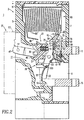
- Figures 1-3 illustrate a power air circuit breaker 1 having a housing 3 which includes a molded front casing 5 and rear casing 7 which together define pole chambers 9 each containing a pole device 11.
- the circuit breaker 1 has three poles, one for each phase in a three-phase system.
- Figures 1-3 are vertical sections through one of the pole chambers 9 taken along slightly different lines to show the pertinent features.
- Each pole includes a line side conductor 13 which projects out of the rear casing 7 for connection to a source of ac electric power (not shown).
- a load conductor 15 also projects out of the rear casing 7 (see Figure 1) for connection typically to the conductors of a load network (also not shown).
- Each pole device 11 has a pair of main contacts 17 which include a stationary main contact 19 and movable main contact 21.
- the movable main contact 21 is carried by a moving conductor assembly 23.
- This movable conductor assembly 23 includes a plurality of contact fingers 25 which are mounted in spaced axial relation on a pivot pin 27 secured in a contact carrier 29.
- the contact carrier 29 has a molded body 31 and a pair of legs 33 (only one shown) having pivots 35 rotatably supported in the housing 3 ( Figure 3).
- the contact carrier is rotated about the pivots 35 by a drive linkage 37 which includes a drive pin 39 which is received in a transverse passage 41 in the carrier body 31 through a slot 43 to which the drive pin 39 is keyed by flats 45.
- the drive pin 39 is fixed on a drive link 47 which pivots in a groove 49 in carrier body 31.
- the other end of the drive link 47 is pivotally connected by a pin 51 to pole arm 53 on a pole shaft 55 similarly connected to carriers in the other poles of the circuit breaker.
- the pole shaft 55 is rotated by an operating mechanism shown schematically at 57 mounted on the front of the front casing 5 and enclosed by a cover (not shown).
- a moving main contact 21 is fixed to each of the contact fingers 25 at a point spaced from the free end of the finger.
- the portion of the contact finger 25 adjacent the free end forms a moving arcing contact or "arc toe" 59.
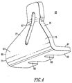
- the stationary arcing contact 61 which together with the arc toe 59 forms a pair of arcing contacts 63 and is provided by the integral arcing contact and runner 65.
- this integral arcing contact and runner 65 is an electrically conductive member having a base section 67 with a base surface 69, an arcing contact section 71 having an arcing contact surface 73, and a runner section 75 having a runner surface 77.
- the integral arcing contact and runner 65 is a sheet metal member made of copper or steel plated with nickel, copper or other suitable material.
- the integral arcing contact and runner 65 is mounted on the line conductor by a bolt 79 which extends through a support block 81, the base section 67, the line conductor 13 and is secured by a nut 80 seated in a slot 82 in the housing, as shown for instance in Figure 2.
- the arcing contact surface 73 of the integral arcing contact and runner 65 is parallel to the stationary main contact 19 but extends laterally farther toward the movable arcing contact or arc toe 59 for a purpose to be discussed.
- the runner section 75 forms an obtuse angle ⁇ with the arcing contact section 71 and leads upward and outward toward one side of an arc chute 83.
- the sheet metal member 65 is bent by an angle ⁇ of less than 90° in forming the arcing contact section 71 and the runner section 75.
- Arc chutes such as 83 are known and include a plurality of arc plates 85 held in spaced relation by a pair of arc side plates 87 (only one shown). At the other side of the arc chute 83 is a top arc plate 89 which extends downward and points toward the moving arcing contact 59, again for a purpose to be described.
- the contact fingers 25 are biased clockwise by pairs of helical compression springs 91 seated in recesses 93 in the carrier body 31.
- the operating mechanism 57 rotates the pole shaft 55 which in turn pivots the contact carrier 29 between open and closed positions to open and close the contacts.
- the contact carrier In the open position shown in Figure 3, the contact carrier is rotated counterclockwise so that the separable main contacts 17 and arcing contacts 63 are fully opened.
- the arc toes 59 contact the arcing contact surface 73 first as shown in Figure 2.
- the springs 91 compress as the contact fingers 25 rock about the pivot pin 27 until the main contacts 17 close.
- the rapid opening of the carrier brings the arc toes 59 adjacent the free end of the arc top plate 89 as shown in Figure 3 so that the arc extends from the arc toe 59 to the arc top plate and moves up the arc top plate into the arc plates 85 which breaks the arc up into shorter sections.
- this stretching of the arc and breaking it up into smaller sections increases the arc voltage.
- the increase in arc voltage, together with the cooling of the arc by ablation of the arc plates 85 promotes interruption of the arc.
- the integral stationary arcing contact and runner 65 eliminates the joint that was present between the prior art arc block forming the stationary arcing contact and the separate arc runner. This makes it easier for the arc to move from the stationary arcing contact 61 to the runner section 75 where it then is directed upward toward the arc chute by the edge created by the slot 97, which in the exemplary configuration is a closed slot. Also, since the arcing contact section 71 is a flat section transverse to the base section 67, the bend to the runner section is not as sharp as in the prior art separate arc runner which had a base section similar to the base section 67 which was then bent more than 90° to the runner section.
- the integral stationary arc contact and runner 65 also has an arcuate section 99 between the arcing contact section 71 and the runner section 75 which provides an arcuate surface 101 without any sharp lateral edges which could divert the arc to the sides or cause hesitation in movement of the arc toward the arc chute.
- the carrier 29 has a feature which concentrates the arc near the center of the stationary arcing contact 61 and therefore helps to direct the arc toward the center slot 97.
- the tail ends 103 of the contact fingers 25 are biased by the springs 91 against a stop ledge 105 on the carrier body 31.
- the center of this stop ledge 105 has a recess 107 (see Figure 1) which allows the center contact fingers 25 to rotate farther clockwise when the carrier is not in the closed position than the outer contact fingers (see Figure 3). Therefore, the arcing contacts 59 on the center contact fingers 25 are the first to contact during closing. More importantly, they are the last to separate on opening so that the arc is struck only between the arcing contacts at the center.
- the movable arcing contacts 59 strike the stationary arcing contacts 61 with a very large force during closing of the circuit breaker.
- the support block 81 transmits the reaction forces from the sheet metal integral arcing contact and runner 65 into the housing 3 to prevent distortion or bending of this sheet metal member.
- the support block could be integrally molded with the rear casing 7 of the housing 3.
Landscapes
- Arc-Extinguishing Devices That Are Switches (AREA)
- Breakers (AREA)
Applications Claiming Priority (2)
| Application Number | Priority Date | Filing Date | Title |
|---|---|---|---|
| US74234 | 1998-05-07 | ||
| US09/074,234 US5969314A (en) | 1998-05-07 | 1998-05-07 | Electrical switching apparatus having arc runner integral with stationary arcing contact |
Publications (3)
| Publication Number | Publication Date |
|---|---|
| EP0955653A2 true EP0955653A2 (fr) | 1999-11-10 |
| EP0955653A3 EP0955653A3 (fr) | 2000-06-28 |
| EP0955653B1 EP0955653B1 (fr) | 2006-04-12 |
Family
ID=22118478
Family Applications (1)
| Application Number | Title | Priority Date | Filing Date |
|---|---|---|---|
| EP99108545A Expired - Lifetime EP0955653B1 (fr) | 1998-05-07 | 1999-05-05 | Appareil de commutation électrique avec cornes d'arc intégrés avec contact fixe d'arc |
Country Status (11)
| Country | Link |
|---|---|
| US (1) | US5969314A (fr) |
| EP (1) | EP0955653B1 (fr) |
| KR (1) | KR100619107B1 (fr) |
| CN (1) | CN1097273C (fr) |
| AU (1) | AU742526B2 (fr) |
| BR (1) | BR9901963A (fr) |
| CA (1) | CA2271247C (fr) |
| DE (1) | DE69930781T2 (fr) |
| EG (1) | EG21686A (fr) |
| IL (1) | IL129470A (fr) |
| SG (1) | SG75948A1 (fr) |
Cited By (1)
| Publication number | Priority date | Publication date | Assignee | Title |
|---|---|---|---|---|
| WO2001039225A1 (fr) * | 1999-11-19 | 2001-05-31 | Siemens Aktiengesellschaft | Configuration de contact de commutation de commande comprenant un module fixe constitue d'un contact d'arc et d'une corne d'arc |
Families Citing this family (24)
| Publication number | Priority date | Publication date | Assignee | Title |
|---|---|---|---|---|
| US6232570B1 (en) * | 1999-09-16 | 2001-05-15 | General Electric Company | Arcing contact arrangement |
| US6376788B1 (en) * | 2001-01-08 | 2002-04-23 | Eaton Corporation | Magnetically collapsible toggle linkage for electrical switching apparatus |
| US6417474B1 (en) | 2001-05-15 | 2002-07-09 | Eaton Corporation | Electrical switching apparatus having an arc runner with an elongated raised ridge |
| US6747533B2 (en) | 2001-10-11 | 2004-06-08 | Eaton Corporation | One piece air-core coil mounting bracket |
| DE10219558B4 (de) * | 2002-04-26 | 2004-08-26 | Siemens Ag | Elektrischer Leistungsschalter mit einer Anschlussschiene und einem Lichtbogenhorn |
| FI116865B (fi) * | 2004-01-19 | 2006-03-15 | Abb Oy | Kytkinlaite |
| US20050279734A1 (en) * | 2004-06-17 | 2005-12-22 | Carothers Arthur D | Arc runner clinch assembly for electrical switching apparatus |
| US7034242B1 (en) | 2004-11-09 | 2006-04-25 | Eaton Corporation | Arc chute and circuit interrupter employing the same |
| US7105764B2 (en) * | 2005-01-13 | 2006-09-12 | Eaton Corporation | Monolithic stationary conductor and current limiting power switch incorporating same |
| US6977568B1 (en) | 2005-01-13 | 2005-12-20 | Eaton Corporation | Blow open moving contact assembly for electric power switching apparatus with a very high current interruption rating |
| DE102005047741B4 (de) * | 2005-09-29 | 2013-02-14 | Siemens Aktiengesellschaft | Elektrischer Schalter |
| US7202436B1 (en) * | 2005-10-28 | 2007-04-10 | Eaton Corporation | Secondary arc chute and electrical switching apparatus incorporating same |
| US7812276B2 (en) * | 2008-04-23 | 2010-10-12 | Eaton Corporation | Electrical switching apparatus, and arc chute and arc member therefor |
| US7830232B2 (en) * | 2009-01-06 | 2010-11-09 | Eaton Corporation | Arc runner assembly and electrical switching apparatus and method incorporating same |
| US9293282B2 (en) | 2010-06-16 | 2016-03-22 | Eaton Corporation | Moving seal with arc creepage surface for an air circuit breaker |
| CN102915894B (zh) * | 2012-10-29 | 2015-10-28 | 大全集团有限公司 | 直流断路器吹弧装置 |
| DE102013111953A1 (de) * | 2012-12-20 | 2014-06-26 | Eaton Electrical Ip Gmbh & Co. Kg | Schaltgerät |
| US9029727B2 (en) * | 2013-01-24 | 2015-05-12 | Eaton Corporation | Arc runners suitable for DC molded case circuit breakers and related methods |
| CN103198984B (zh) * | 2013-04-10 | 2015-05-27 | 四川中光防雷科技股份有限公司 | 一种高安全性电涌保护器 |
| CN105448616B (zh) * | 2015-12-31 | 2018-05-22 | 苏州万龙工控自动化有限公司 | 分散式接触动触头装置 |
| CN208240528U (zh) * | 2018-04-19 | 2018-12-14 | 施耐德电气工业公司 | 静触头组件和相应的开关触头 |
| US10483068B1 (en) | 2018-12-11 | 2019-11-19 | Eaton Intelligent Power Limited | Switch disconnector systems suitable for molded case circuit breakers and related methods |
| CN114678239B (zh) * | 2021-12-24 | 2023-09-29 | 河南平高通用电气有限公司 | 一种直流断路器的动侧触头组件及直流断路器 |
| CN114743826A (zh) * | 2022-04-01 | 2022-07-12 | 江苏大全凯帆开关股份有限公司 | 一种两极直流负荷开关 |
Citations (2)
| Publication number | Priority date | Publication date | Assignee | Title |
|---|---|---|---|---|
| GB1001239A (en) * | 1962-06-01 | 1965-08-11 | Reyrolle A & Co Ltd | Improvements relating to air-break electric circuit-breakers |
| EP0410902A1 (fr) * | 1989-07-26 | 1991-01-30 | Merlin Gerin | Disjoncteur basse tension à contacts multiples et à fortes intensités |
Family Cites Families (7)
| Publication number | Priority date | Publication date | Assignee | Title |
|---|---|---|---|---|
| US2471608A (en) * | 1944-04-22 | 1949-05-31 | Ite Circuit Breaker Ltd | Circuit breaker contact construction |
| DE1161350B (de) * | 1961-03-13 | 1964-01-16 | Licentia Gmbh | Kontaktanordnung fuer elektrische Selbstschalter mit strombegrenzender Ausschaltcharakteristik |
| US3662134A (en) * | 1969-06-11 | 1972-05-09 | Westinghouse Electric Corp | Circuit breaker with improved current path and contact means |
| US4229630A (en) * | 1980-03-17 | 1980-10-21 | Westinghouse Electric Corp. | Circuit breaker utilizing improved arc chambers |
| US4713504A (en) * | 1986-03-03 | 1987-12-15 | Westinghouse Electric Corp. | Circuit breaker with hinged arcing contact |
| US5057806A (en) * | 1988-08-01 | 1991-10-15 | Westinghouse Electric Corp. | Crossbar assembly |
| US4871889A (en) * | 1988-09-21 | 1989-10-03 | Siemens Energy & Automation, Inc. | Arcing contact assembly for a circuit breaker |
-
1998
- 1998-05-07 US US09/074,234 patent/US5969314A/en not_active Expired - Lifetime
-
1999
- 1999-04-15 IL IL12947099A patent/IL129470A/xx not_active IP Right Cessation
- 1999-04-21 SG SG1999001899A patent/SG75948A1/en unknown
- 1999-04-22 AU AU23891/99A patent/AU742526B2/en not_active Ceased
- 1999-05-03 BR BR9901963-9A patent/BR9901963A/pt not_active IP Right Cessation
- 1999-05-04 KR KR1019990016034A patent/KR100619107B1/ko not_active IP Right Cessation
- 1999-05-05 DE DE69930781T patent/DE69930781T2/de not_active Expired - Lifetime
- 1999-05-05 EP EP99108545A patent/EP0955653B1/fr not_active Expired - Lifetime
- 1999-05-05 EG EG50699A patent/EG21686A/xx active
- 1999-05-06 CN CN99106336A patent/CN1097273C/zh not_active Expired - Lifetime
- 1999-05-06 CA CA002271247A patent/CA2271247C/fr not_active Expired - Lifetime
Patent Citations (2)
| Publication number | Priority date | Publication date | Assignee | Title |
|---|---|---|---|---|
| GB1001239A (en) * | 1962-06-01 | 1965-08-11 | Reyrolle A & Co Ltd | Improvements relating to air-break electric circuit-breakers |
| EP0410902A1 (fr) * | 1989-07-26 | 1991-01-30 | Merlin Gerin | Disjoncteur basse tension à contacts multiples et à fortes intensités |
Cited By (1)
| Publication number | Priority date | Publication date | Assignee | Title |
|---|---|---|---|---|
| WO2001039225A1 (fr) * | 1999-11-19 | 2001-05-31 | Siemens Aktiengesellschaft | Configuration de contact de commutation de commande comprenant un module fixe constitue d'un contact d'arc et d'une corne d'arc |
Also Published As
| Publication number | Publication date |
|---|---|
| KR19990088050A (ko) | 1999-12-27 |
| KR100619107B1 (ko) | 2006-09-01 |
| EP0955653A3 (fr) | 2000-06-28 |
| EG21686A (en) | 2002-02-27 |
| IL129470A (en) | 2003-06-24 |
| DE69930781D1 (de) | 2006-05-24 |
| AU2389199A (en) | 1999-11-18 |
| CA2271247C (fr) | 2008-03-11 |
| BR9901963A (pt) | 2000-01-18 |
| DE69930781T2 (de) | 2007-04-12 |
| IL129470A0 (en) | 2000-02-29 |
| US5969314A (en) | 1999-10-19 |
| AU742526B2 (en) | 2002-01-03 |
| CN1097273C (zh) | 2002-12-25 |
| EP0955653B1 (fr) | 2006-04-12 |
| CA2271247A1 (fr) | 1999-11-07 |
| CN1238540A (zh) | 1999-12-15 |
| SG75948A1 (en) | 2000-10-24 |
Similar Documents
| Publication | Publication Date | Title |
|---|---|---|
| US5969314A (en) | Electrical switching apparatus having arc runner integral with stationary arcing contact | |
| EP1388154B1 (fr) | Dispositif de commutation electrique comprenant une spire conductrice munie d'une arete saillante allongee | |
| AU2002304367A1 (en) | Electrical switching apparatus having an arc runner with an elongated raised ridge | |
| US5210385A (en) | Low voltage circuit breaker with multiple contacts for high currents | |
| US4263492A (en) | Circuit breaker with anti-bounce mechanism | |
| CN110998771B (zh) | 电气开关设备及其碎屑屏障 | |
| US5874699A (en) | Molded case circuit breaker and moving conductor assembly therefor | |
| CA1167495A (fr) | Disjoncteur multipolaire a dispositif limiteur d'intensite perfectionne | |
| CA1140189A (fr) | Disjoncteur a dispositif d'extinction d'arc ameliore | |
| CA2213671C (fr) | Interrupteur a manoeuvrer par perche isolante | |
| PL198718B1 (pl) | Układ zestyku opalnego | |
| CA1127690A (fr) | Contacts de decharge en arc doubles pour disjoncteur | |
| EP0095038A2 (fr) | Disjoncteur limiteur de courant ayant un dispositif de contact amélioré | |
| EP0208295A2 (fr) | Disjoncteur de limitation de courant avec structure de commutation de l'arc | |
| MXPA99004244A (es) | Aparato interruptor electrico que tiene corredor de arco integral con contacto estacionario que forma arco | |
| EP0898292A2 (fr) | Appareil de commande electrique | |
| EP1346385B1 (fr) | Disjoncteur de limitation de courant automatique | |
| IE61137B1 (en) | Circuit breaker | |
| US20220344120A1 (en) | Slim circuit breaker | |
| JPH0334234A (ja) | 回路遮断器 | |
| JP4407072B2 (ja) | 回路遮断器 | |
| JPH0381919A (ja) | ガス絶縁開閉器 | |
| JPH09171758A (ja) | 回路遮断器 |
Legal Events
| Date | Code | Title | Description |
|---|---|---|---|
| PUAI | Public reference made under article 153(3) epc to a published international application that has entered the european phase |
Free format text: ORIGINAL CODE: 0009012 |
|
| AK | Designated contracting states |
Kind code of ref document: A2 Designated state(s): DE FR GB |
|
| AX | Request for extension of the european patent |
Free format text: AL;LT;LV;MK;RO;SI |
|
| PUAL | Search report despatched |
Free format text: ORIGINAL CODE: 0009013 |
|
| AK | Designated contracting states |
Kind code of ref document: A3 Designated state(s): AT BE CH CY DE DK ES FI FR GB GR IE IT LI LU MC NL PT SE |
|
| AX | Request for extension of the european patent |
Free format text: AL;LT;LV;MK;RO;SI |
|
| 17P | Request for examination filed |
Effective date: 20001205 |
|
| AKX | Designation fees paid |
Free format text: DE FR GB |
|
| 17Q | First examination report despatched |
Effective date: 20040428 |
|
| GRAP | Despatch of communication of intention to grant a patent |
Free format text: ORIGINAL CODE: EPIDOSNIGR1 |
|
| GRAC | Information related to communication of intention to grant a patent modified |
Free format text: ORIGINAL CODE: EPIDOSCIGR1 |
|
| GRAS | Grant fee paid |
Free format text: ORIGINAL CODE: EPIDOSNIGR3 |
|
| GRAA | (expected) grant |
Free format text: ORIGINAL CODE: 0009210 |
|
| AK | Designated contracting states |
Kind code of ref document: B1 Designated state(s): DE FR GB |
|
| REG | Reference to a national code |
Ref country code: GB Ref legal event code: FG4D |
|
| REF | Corresponds to: |
Ref document number: 69930781 Country of ref document: DE Date of ref document: 20060524 Kind code of ref document: P |
|
| RAP2 | Party data changed (patent owner data changed or rights of a patent transferred) |
Owner name: EATON CORPORATION |
|
| ET | Fr: translation filed | ||
| PLBE | No opposition filed within time limit |
Free format text: ORIGINAL CODE: 0009261 |
|
| STAA | Information on the status of an ep patent application or granted ep patent |
Free format text: STATUS: NO OPPOSITION FILED WITHIN TIME LIMIT |
|
| 26N | No opposition filed |
Effective date: 20070115 |
|
| PGFP | Annual fee paid to national office [announced via postgrant information from national office to epo] |
Ref country code: GB Payment date: 20080407 Year of fee payment: 10 |
|
| GBPC | Gb: european patent ceased through non-payment of renewal fee |
Effective date: 20090505 |
|
| PG25 | Lapsed in a contracting state [announced via postgrant information from national office to epo] |
Ref country code: GB Free format text: LAPSE BECAUSE OF NON-PAYMENT OF DUE FEES Effective date: 20090505 |
|
| PGFP | Annual fee paid to national office [announced via postgrant information from national office to epo] |
Ref country code: FR Payment date: 20100525 Year of fee payment: 12 |
|
| REG | Reference to a national code |
Ref country code: FR Ref legal event code: ST Effective date: 20120131 |
|
| PG25 | Lapsed in a contracting state [announced via postgrant information from national office to epo] |
Ref country code: FR Free format text: LAPSE BECAUSE OF NON-PAYMENT OF DUE FEES Effective date: 20110531 |
|
| PGFP | Annual fee paid to national office [announced via postgrant information from national office to epo] |
Ref country code: DE Payment date: 20180419 Year of fee payment: 20 |
|
| REG | Reference to a national code |
Ref country code: DE Ref legal event code: R082 Ref document number: 69930781 Country of ref document: DE Ref country code: DE Ref legal event code: R081 Ref document number: 69930781 Country of ref document: DE Owner name: EATON INTELLIGENT POWER LIMITED, IE Free format text: FORMER OWNER: EATON CORP., CLEVELAND, OHIO, US |
|
| REG | Reference to a national code |
Ref country code: DE Ref legal event code: R071 Ref document number: 69930781 Country of ref document: DE |