EP0955186A2 - Pneumatic radial tires - Google Patents
Pneumatic radial tires Download PDFInfo
- Publication number
- EP0955186A2 EP0955186A2 EP99303557A EP99303557A EP0955186A2 EP 0955186 A2 EP0955186 A2 EP 0955186A2 EP 99303557 A EP99303557 A EP 99303557A EP 99303557 A EP99303557 A EP 99303557A EP 0955186 A2 EP0955186 A2 EP 0955186A2
- Authority
- EP
- European Patent Office
- Prior art keywords
- widthwise
- belt layer
- outer end
- layer
- maximum
- Prior art date
- Legal status (The legal status is an assumption and is not a legal conclusion. Google has not performed a legal analysis and makes no representation as to the accuracy of the status listed.)
- Granted
Links
Images


Classifications
-
- B—PERFORMING OPERATIONS; TRANSPORTING
- B60—VEHICLES IN GENERAL
- B60C—VEHICLE TYRES; TYRE INFLATION; TYRE CHANGING; CONNECTING VALVES TO INFLATABLE ELASTIC BODIES IN GENERAL; DEVICES OR ARRANGEMENTS RELATED TO TYRES
- B60C9/00—Reinforcements or ply arrangement of pneumatic tyres
- B60C9/18—Structure or arrangement of belts or breakers, crown-reinforcing or cushioning layers
- B60C9/28—Structure or arrangement of belts or breakers, crown-reinforcing or cushioning layers characterised by the belt or breaker dimensions or curvature relative to carcass
-
- B—PERFORMING OPERATIONS; TRANSPORTING
- B60—VEHICLES IN GENERAL
- B60C—VEHICLE TYRES; TYRE INFLATION; TYRE CHANGING; CONNECTING VALVES TO INFLATABLE ELASTIC BODIES IN GENERAL; DEVICES OR ARRANGEMENTS RELATED TO TYRES
- B60C9/00—Reinforcements or ply arrangement of pneumatic tyres
- B60C9/18—Structure or arrangement of belts or breakers, crown-reinforcing or cushioning layers
- B60C9/20—Structure or arrangement of belts or breakers, crown-reinforcing or cushioning layers built-up from rubberised plies each having all cords arranged substantially parallel
- B60C9/2003—Structure or arrangement of belts or breakers, crown-reinforcing or cushioning layers built-up from rubberised plies each having all cords arranged substantially parallel characterised by the materials of the belt cords
- B60C9/2009—Structure or arrangement of belts or breakers, crown-reinforcing or cushioning layers built-up from rubberised plies each having all cords arranged substantially parallel characterised by the materials of the belt cords comprising plies of different materials
-
- B—PERFORMING OPERATIONS; TRANSPORTING
- B60—VEHICLES IN GENERAL
- B60C—VEHICLE TYRES; TYRE INFLATION; TYRE CHANGING; CONNECTING VALVES TO INFLATABLE ELASTIC BODIES IN GENERAL; DEVICES OR ARRANGEMENTS RELATED TO TYRES
- B60C9/00—Reinforcements or ply arrangement of pneumatic tyres
- B60C9/18—Structure or arrangement of belts or breakers, crown-reinforcing or cushioning layers
- B60C9/20—Structure or arrangement of belts or breakers, crown-reinforcing or cushioning layers built-up from rubberised plies each having all cords arranged substantially parallel
- B60C2009/2041—Structure or arrangement of belts or breakers, crown-reinforcing or cushioning layers built-up from rubberised plies each having all cords arranged substantially parallel with an interrupted belt ply, e.g. using two or more portions of the same ply
-
- Y—GENERAL TAGGING OF NEW TECHNOLOGICAL DEVELOPMENTS; GENERAL TAGGING OF CROSS-SECTIONAL TECHNOLOGIES SPANNING OVER SEVERAL SECTIONS OF THE IPC; TECHNICAL SUBJECTS COVERED BY FORMER USPC CROSS-REFERENCE ART COLLECTIONS [XRACs] AND DIGESTS
- Y10—TECHNICAL SUBJECTS COVERED BY FORMER USPC
- Y10T—TECHNICAL SUBJECTS COVERED BY FORMER US CLASSIFICATION
- Y10T152/00—Resilient tires and wheels
- Y10T152/10—Tires, resilient
- Y10T152/10495—Pneumatic tire or inner tube
- Y10T152/10765—Characterized by belt or breaker structure
- Y10T152/10792—Structure where each bias angle reinforcing cord ply has no opposingly angled ply
-
- Y—GENERAL TAGGING OF NEW TECHNOLOGICAL DEVELOPMENTS; GENERAL TAGGING OF CROSS-SECTIONAL TECHNOLOGIES SPANNING OVER SEVERAL SECTIONS OF THE IPC; TECHNICAL SUBJECTS COVERED BY FORMER USPC CROSS-REFERENCE ART COLLECTIONS [XRACs] AND DIGESTS
- Y10—TECHNICAL SUBJECTS COVERED BY FORMER USPC
- Y10T—TECHNICAL SUBJECTS COVERED BY FORMER US CLASSIFICATION
- Y10T152/00—Resilient tires and wheels
- Y10T152/10—Tires, resilient
- Y10T152/10495—Pneumatic tire or inner tube
- Y10T152/10765—Characterized by belt or breaker structure
- Y10T152/10801—Structure made up of two or more sets of plies wherein the reinforcing cords in one set lie in a different angular position relative to those in other sets
Definitions
- This invention relates to a pneumatic radial tire capable of controlling separation failure at belt end.
- an end portion of the tread in the pneumatic radial tire is subjected to a tensional deformation in the circumferential direction every the contacting with a flat road surface due to an influence of crown radius.
- At the tread end portion subjected to such a tensional deformation are located outer side end portions of plural belt layers in which cords are slantly embedded in these layers in opposite directions with respect to an equatorial plane of the tire, so that the cords crossed with each other at this position are subjected to the above tensional deformation every the arrival at the ground contacting region and repeatedly deform in a direction of crushing a diamond shape.
- the ends of the cords embedded in the belt layer are exposed at the outer end of the belt layer in the widthwise direction and are cut faces not subjected to brass plating or the like for enhancing an adhesion to rubber, so that the ends of the cords are repeatedly pulled apart from the surrounding rubber due to the influence of the above tensile strain and hence slight cracks are created in the rubber located in the vicinity of the cord ends exposed at the outer end of the belt layer in the widthwise direction.
- the aforementioned displacement becomes maximum at a widthwise outer end of a narrow-width belt layer arranged at an outside of a maximum-width belt layer in the radial direction and containing cords arranged in an oppositely inclination direction to cords of the maximum-width belt layer.
- a pneumatic radial tire comprising a radial carcass of at least one rubberized cord ply toroidally extending between a pair of bead cores, a belt superimposed about a crown portion of the carcass and comprised of at least two belt layers, and a tread arranged at an outside of the belt in a radial direction
- the belt comprises a maximum-width belt layer containing many cords slantly arranged with respect to an equatorial plane of the tire and a narrow-width belt layer arranged at the outside of the maximum-width belt layer in the radial direction and containing many cords arranged in an oppositely inclined direction to the cords of the maximum-width belt layer
- an improvement wherein a reinforcing layer containing many cords arranged in an oppositely inclined direction to the cords of the maximum-width belt layer is arranged so as to overlap with an outer end portion of the maximum-width belt layer located outward from an outer end of the
- the reinforcing layer when the reinforcing layer is arranged so as to overlap with the widthwise outer end portion of the maximum-width belt layer located outward from the widthwise outer end of the narrow-width belt layer in the widthwise direction and contains many cords arranged in an oppositely inclination direction to the cords of the maximum-width belt layer, a diamond shape defined by the cords embedded in the reinforcing layer and the cords embedded in the maximum-width belt layer are also deformed in a crushed direction due to the same tensional deformation in the circumferential direction as mentioned above, so that the reinforcing layer, widthwise outer end portion of the maximum-width belt layer and rubber surrounding them (including rubber located outward from the widthwise outer end of the narrow-width belt layer in the widthwise direction) displace inward in the widthwise direction together, whereby the tensile strain in the widthwise direction produced at the boundary between the widthwise outer end of the narrow-width belt layer and the rubber located outward from the widthwise outer end in the widthwise direction is
- the cords of the reinforcing layer are inextensible cords and the reinforcing layer is closely arranged at the inside of the maximum-width belt layer in the radial direction, or the widthwise outer end of the reinforcing layer is located inward from the widthwise outer end of the maximum-width belt layer in the widthwise direction, whereby the belt end separation of the narrow-width belt layer can surely be prevented while controlling the separation failure at the widthwise outer end of the reinforcing layer.
- the widthwise inner end of the reinforcing layer is located in the vicinity of the widthwise outer end of the narrow-width belt layer and an inclination angle A of the cord embedded in the reinforcing layer with respect to the equatorial plane of the tire is within a range of 4° to 60°. In this case, the belt end separation of the narrow-width belt layer can further be prevented.
- the reinforcing layer is extended inward in the widthwise direction so as to form a one-piece body on the equatorial plane and an inclination angle B of the cord embedded in the reinforcing layer is not less than 34° with respect to the equatorial plane.
- an inclination angle B of the cord embedded in the reinforcing layer is not less than 34° with respect to the equatorial plane.
- the cords of the reinforcing layer are organic fiber cords and the reinforcing layer is arranged at the outside of the maximum-width belt layer in the radial direction. Even in this case, the belt end separation of the narrow-width belt layer can effectively be prevented.
- the widthwise inner end of the reinforcing layer is located at the outside of the narrow-width belt layer in the radial direction and inward from the widthwise outer end thereof in the widthwise direction, and the widthwise outer end of the reinforcing layer is located outward from the widthwise outer end of the maximum-width belt layer in the widthwise direction, or further an inclination angle C of the cord embedded in the reinforcing layer is not less than 7° with respect to the equatorial plane. In this case, the belt end separation of the narrow-width belt layer can surely be prevented.
- numeral 11 is a first embodiment of the heavy duty pneumatic radial tire for use in truck and bus according to the invention.
- the tire 11 comprises a pair of bead portions 13, a pair of sidewall portions 14 extending outward from these bead portions 13 in a radial direction of the tire, and a tread portion 15 of an approximately cylindrical form connecting radially outer ends of the sidewall portions 14 to each other.
- the tire 11 comprises a carcass 18 toroidally extending between a pair of bead cores 17 embedded in the bead portions 13 and reinforcing the sidewall portions 14 and the tread portion 15. Each end portion of the carcass 18 is wound around the bead core 17 provided with a stiffener 19 from inside of the tire toward outside thereof.
- the carcass 18 is comprised of at least one rubberized carcass ply, one carcass ply 20 in this embodiment, which contains many inextensible cords 21 such as steel cords embedded therein and extending substantially in the radial direction (which are inclined at an angle of 80-90° with respect to an equatorial plane S of the tire).
- Numeral 24 is a belt arranged at the outside of the carcass 18 in the radial direction, which is comprised by laminating at least two belt layers (three belt layers in the illustrated embodiment).
- a maximum-width belt layer 25 having a widest width is arranged at an innermost side in the radial direction
- a narrow-width belt layer 26 having a width somewhat narrower than the width of the maximum-width belt layer 25 is arranged at the outside of the maximum-width belt layer 25 in the radial direction and adjacent thereto
- a minimum-width belt layer 27 having a width fairly narrower than the width of the narrow-width belt layer 26 is arranged at the outside of the narrow-width belt layer 26 in the radial direction and adjacent thereto.
- the cords embedded in each belt layer are inclined within a range of 10-25° with respect to the equatorial plane S, and the cords of at least two belt layers among these belt layers are crossed with each other.
- the inclination angle of the cord 28 in the maximum-width belt layer 25 is 18° upward to the right
- the inclination angle of the cord 29 in the narrow-width belt layer 26 is 18° upward to the left
- the inclination angle of the cord 30 in the minimum-width belt layer 27 is 18° upward to the right
- the inclination directions of the cords in these adjoining belt layers are opposite to each other.
- a cushion rubber 31 having substantially a triangular shape at a section and a maximum gauge at a widthwise outer end 29a of the narrow-width belt layer 26 is interposed between a widthwise outer end portion of the maximum-width belt layer 25 and a widthwise outer end portion of the narrow-width belt layer 26.
- Numeral 32 is a tread arranged at the outside of the belt 24 in the radial direction.
- a plurality of main grooves 33 extending in the circumferential direction and many lateral grooves (not shown) crossing with these main grooves 33.
- Numeral 35 is a pair of reinforcing layers.
- the reinforcing layer 35 is arranged so as to overlap with the widthwise outer end portion 25a of the maximum-width belt layer 25 or a portion of the maximum-width belt layer 25 located outward from the widthwise outer end 26a of the narrow-width belt layer 26.
- In the reinforcing layer 35 are embedded many cords 36 slantly arranged with respect to the equatorial plane S and in parallel to each other, in which the inclination direction of the cord 36 is opposite to that of the cord 28 in the maximum-width belt layer 25.
- the reinforcing layer 35 containing many cords 36 arranged in a direction opposite to the cords 28 of the maximum-width belt layer 25 is arranged so as to overlap with the widthwise outer end portion 25a of the maximum-width belt layer 25, the diamond shape defined by the cords 36 of the reinforcing layer 35 and the cords 28 existing in the widthwise outer end portion 25a of the maximum-width belt layer 25 is deformed in a crushed form due to the tensional deformation in the circumferential direction at the ground contact region of the running tire 11.
- the reinforcing layer 35, the widthwise outer end portion 25a of the maximum-width belt layer 25 and rubber surrounding them displace inward in the widthwise direction together, so that the tensile strain in the widthwise direction produced at the boundary between the widthwise outer end 26a of the narrow-width belt layer 26 and the rubber located outward from the widthwise outer end 26a in the widthwise direction is decreased (or it is a compression strain according to circumstances), whereby the occurrence and development of cracks in the rubber located in the vicinity of ends of the cords 29 in the narrow-width belt layer 26 are effectively controlled. In this way, the belt end separation of the narrow-width belt layer 26 is also prevented effectively.
- the cord 36 in the reinforcing layer 35 is an inextensible cord such as steel cord or aramid cord
- the influence of such a cord to the cord 28 embedded in the widthwise outer end portion 25a becomes larger and the control of the separation failure can be ensured.
- the reinforcing layer 35 containing the inextensible cords 36 therein is arranged at the outside of the widthwise outer end portion 25a in the radial direction, stress concentration occurs in the widthwise outer end 35a of the reinforcing layer 35 and there is feared the occurrence of separation failure prior to the belt end separation in the widthwise outer end 26a of the narrow-width belt layer 26.
- the reinforcing layer 35 is closely arranged at the inside of the widthwise outer end portion 25a of the maximum-width belt layer 25 in the radial direction largely exerting upon the effect of controlling the widthwise deformation through the carcass 18 as in the illustrated embodiment.
- the width of the reinforcing layer 35 is widened so as to locate the widthwise outer end 35a outward from the widthwise outer end 25b of the maximum-width belt layer 25, a large tensile strain is created in the widthwise outer end 35a of the reinforcing layer 35 and hence there is feared the occurrence of the separation failure at the widthwise outer end 35a of the reinforcing layer 35 rather than the widthwise outer end 26a of the narrow-width belt layer 26. Therefore, it is favorable that the widthwise outer end 35a of the reinforcing layer 35 is located inward from the widthwise outer end 25b of the maximum-width belt layer 25 in the widthwise direction as in illustrated embodiment.
- the width of the reinforcing layer 35 is narrowed so as to terminate the widthwise inner end 35b in the vicinity of the widthwise outer end 26a of the narrow-width belt layer 26.
- an inclination angle A of the cord 36 in the reinforcing layer 35 with respect to the equatorial plane S is within a range of 4-60°, preferably not more than 50°.
- the inclination angle A is 10°.
- a radial tire for truck and bus having a tire size of 11R22.5 and comprising maximum-width, narrow-width and minimum-width belt layers as shown in Figs. 1 and 2, each of which layers containing steel cords of 3 ⁇ 0.2 + 6 ⁇ 0.38 mm arranged at an end count of 25 cords/5 cm and inclined at the aforementioned angle, and a reinforcing layer containing steel cords of 3 ⁇ 0.2 + 6 ⁇ 0.38 mm arranged at an end count of 25 cords/5 cm as shown in Figs.
- the widths of the maximum-width, narrow-width and minimum-width belt layers and the reinforcing layer are 180 mm, 150 mm, 80 mm and 20 mm, respectively, and the widthwise outer end of the reinforcing layer is located inward by 7 mm from the widthwise outer end of the maximum-width belt layer in the widthwise direction.
- the tensile strain in widthwise direction in Fig. 3 is represented by an index on the basis that strain produced in the widthwise outer end of the narrow-width belt layer including no reinforcing layer is 1.
- a reinforcing layer 38 is comprised of a single layer continued in the widthwise direction by extending each of the reinforcing layers as in the first embodiment inward in the widthwise direction and integrally uniting them at the equatorial plane S in order to enhance the hoop effect of the belt 24 while simplifying the production.
- an inclination angle B of an inextensible cord 39 such as steel cord embedded in the reinforcing layer 38 is not less than 34°. In this embodiment, the inclination angle B is 52° upward to the left.
- portions of the cords 39 in the reinforcing layer 38 existing so as to overlap with the widthwise outer end portion 25a of the maximum-width belt layer 25 act to displace rubber surrounding the widthwise outer end portion 25a inward in the widthwise direction as mentioned in the first embodiment, while portions of the cords 39 overlapping with the central portion 25c of the maximum-width belt layer 25 extend substantially in the widthwise direction so as to serve as a strut bar, whereby the narrowing of the widthwise central portion 25c is controlled and hence the tensile strain in the widthwise direction at the widthwise outer end 26a of the narrow-width belt layer 26 is effectively controlled.
- a reinforcing layer 44 is comprised of organic fiber cords 45 having a small stiffness instead of the inextensible cord such as steel cord. Since the organic fiber cord is low in the influence upon the cord 28 at the widthwise outer end portion 25a, if the reinforcing layer 44 is arranged at the inside of the maximum-width belt layer 25 in the radial direction, rubber located at the outside of the widthwise outer end portion 25a in the radial direction can not sufficiently be displaced inward in the radial direction.
- the reinforcing layer 44 is arranged at the outside of the widthwise outer end portion 25a in the radial direction to sandwich rubber located at the outside of the widthwise outer end portion 25a in the radial direction between the widthwise outer end portion 25a and the reinforcing layer 44, whereby the influence upon the rubber is enhanced to ensure the displacement inward in the radial direction.
- the reinforcing layer 44 is arranged outward at a certain distance from the widthwise outer end portion 25a in the radial direction, so that the displacement of the cushion rubber 31 inward in the radial direction through the widthwise outer end portion 25a and the reinforcing layer 44 becomes small.
- the widthwise outer end 44a of the reinforcing layer 44 is located outward from the widthwise outer end 25a of the maximum-width belt layer 25 in the widthwise direction and the widthwise inner end 44b of the reinforcing layer 44 is located at the outside of the narrow-width belt layer 26 in the radial direction and inward from the widthwise outer end 26a of the narrow-width belt layer 26 in the widthwise direction, whereby the widthwise outer ends 25b, 26a of the maximum-width belt layer 25 and the narrow-width belt layer 26 are covered with the reinforcing layer 44 so as to largely displace the cushion rubber 31 inward in the radial direction.
- an inclination angle C of the cord 45 in the reinforcing layer 44 is not less than 7° with respect to the equatorial plane S of the tire.
- the cords 45 are extended substantially in the circumferential direction and hence the tensile strain in the widthwise direction at the widthwise outer end 26a of the narrow-width belt layer 26 can not effectively be controlled as shown in Fig. 9.
- the conditions for the data shown in Fig. 9 are the same as the conditions for the data shown in Fig.
- the reinforcing layer containing organic fiber cords of nylon-6 (1260 d/2) arranged at an end count of 30 cords/5 cm and inclined at an angle C of 20° with respect to the equatorial plane S is arranged at the outsides of the maximum-width belt layer and the narrow-width belt layer as shown in Figs. 7 and 8 and the widthwise outer end of the reinforcing layer is located outward by 15 mm from the widthwise outer end of the maximum-width belt layer in the widthwise direction and the widthwise inner end thereof is located inward by 30 mm from the widthwise outer end of the narrow-width belt layer in the widthwise direction.
- the widthwise inner end of the reinforcing layer 44 is extended in the vicinity of the widthwise outer end of the minimum-width belt layer 27 so as to cover the widthwise outer end portion of the narrow-width belt layer from the outside in the radial direction.
- the reinforcing layer 44 used in the third embodiment may be added to the tire 11 shown in the first embodiment, or the reinforcing layer 44 used in the third embodiment may be added to the tire shown in the second embodiment, whereby the belt end separation can more surely be controlled.
- each of these tires is mounted onto a truck and run on general-purpose road including unpaved road over a distance of 70,000 km.
- the tire is cut to measure a length of crack created in the widthwise outer end of the narrow-width belt layer.
- the index value of the crack length in the test tires 1, 2, 3, 4 and 5 is 50, 30, 55, 28 and 33, respectively.
- the belt end separation can effectively be prevented in the pneumatic radial tire.
Abstract
Description
- This invention relates to a pneumatic radial tire capable of controlling separation failure at belt end.
- There are known pneumatic radial tires for truck, bus and the like, which are particularly used under a heavy load and recapped plural times after the wearing of a tire tread. In this type of the tire, there has recently been caused a problem that cracks are created at a side end of a belt layer in a widthwise direction thereof in the use over a long time of period and grow inward in the widthwise direction or outward in the radial direction between the belt layers with the lapse of time to cause a separation failure and hence make the use of the tire impossible. Such cracks are considered to be created due to the following fact. That is, an end portion of the tread in the pneumatic radial tire is subjected to a tensional deformation in the circumferential direction every the contacting with a flat road surface due to an influence of crown radius. At the tread end portion subjected to such a tensional deformation are located outer side end portions of plural belt layers in which cords are slantly embedded in these layers in opposite directions with respect to an equatorial plane of the tire, so that the cords crossed with each other at this position are subjected to the above tensional deformation every the arrival at the ground contacting region and repeatedly deform in a direction of crushing a diamond shape. And also, such a deformation is caused when the tread end portion of the tire rides on projections such as stones and the like during the running on bad road to largely deform rubber in this end portion. As the cords are deformed as mentioned above, the width of the belt layer becomes narrow and hence the outer end of the belt layer in the widthwise direction somewhat displaces inward in the widthwise direction repeatedly, while rubber located outward from the outer end of the belt layer in the widthwise direction is left at this position. As a result, tensile strain in the widthwise direction is caused at the boundary between the rubber and the outer end of the belt layer in the widthwise direction. Moreover, the ends of the cords embedded in the belt layer are exposed at the outer end of the belt layer in the widthwise direction and are cut faces not subjected to brass plating or the like for enhancing an adhesion to rubber, so that the ends of the cords are repeatedly pulled apart from the surrounding rubber due to the influence of the above tensile strain and hence slight cracks are created in the rubber located in the vicinity of the cord ends exposed at the outer end of the belt layer in the widthwise direction. On the other hand, the aforementioned displacement becomes maximum at a widthwise outer end of a narrow-width belt layer arranged at an outside of a maximum-width belt layer in the radial direction and containing cords arranged in an oppositely inclination direction to cords of the maximum-width belt layer. Therefore, it is considered that the above slight cracks are first created at the widthwise outer end of the narrow-width belt layer and developed by shearing strain or the like repeatedly produced between the belt layers during the running with the lapse of time to cause separation failure at belt end (hereinafter referred to as belt end separation).
- In order to solve this problem, there have hitherto been proposed a method of arranging a low-hardness and thick cushion rubber between the widthwise outer end of the maximum-width belt layer and the widthwise outer end of the narrow-width belt layer for controlling the shearing strain produced between the belt layers to prevent the development of the cracks, and a method of piling a reinforcing layer containing cords extended substantially in the circumferential direction on the belt layer for controlling the increase of the size of the belt layer accompanied with the inflation under inner pressure or the running to prevent the development of the cracks.
- However, these methods can develop an effect to a certain level, but have a problem that the occurrence of the belt end separation can not sufficiently be controlled.
- It is, therefore, an object of the invention to provide a pneumatic radial tire capable of effectively controlling the belt end separation.
- According to the invention, there is the provision of in a pneumatic radial tire comprising a radial carcass of at least one rubberized cord ply toroidally extending between a pair of bead cores, a belt superimposed about a crown portion of the carcass and comprised of at least two belt layers, and a tread arranged at an outside of the belt in a radial direction, in which the belt comprises a maximum-width belt layer containing many cords slantly arranged with respect to an equatorial plane of the tire and a narrow-width belt layer arranged at the outside of the maximum-width belt layer in the radial direction and containing many cords arranged in an oppositely inclined direction to the cords of the maximum-width belt layer, an improvement wherein a reinforcing layer containing many cords arranged in an oppositely inclined direction to the cords of the maximum-width belt layer is arranged so as to overlap with an outer end portion of the maximum-width belt layer located outward from an outer end of the narrow-width belt layer in the widthwise direction thereof.
- When the cords embedded in the widthwise outer end portions of the maximum-width belt layer and the narrow-width belt layer arrive at a ground contact region during the running of the pneumatic radial tire, a diamond shape defined by these cords is deformed in a crushed direction due to the influence of a crown curvature, whereby the widthwise outer end of the narrow-width belt layer displaces inward in the widthwise direction at maximum. Therefore, when the reinforcing layer is arranged so as to overlap with the widthwise outer end portion of the maximum-width belt layer located outward from the widthwise outer end of the narrow-width belt layer in the widthwise direction and contains many cords arranged in an oppositely inclination direction to the cords of the maximum-width belt layer, a diamond shape defined by the cords embedded in the reinforcing layer and the cords embedded in the maximum-width belt layer are also deformed in a crushed direction due to the same tensional deformation in the circumferential direction as mentioned above, so that the reinforcing layer, widthwise outer end portion of the maximum-width belt layer and rubber surrounding them (including rubber located outward from the widthwise outer end of the narrow-width belt layer in the widthwise direction) displace inward in the widthwise direction together, whereby the tensile strain in the widthwise direction produced at the boundary between the widthwise outer end of the narrow-width belt layer and the rubber located outward from the widthwise outer end in the widthwise direction is decreased (or it is a compression strain according to circumstances). As a result, the occurrence and development of cracks in the rubber located in the vicinity of cord ends of the narrow-width belt layer are effectively controlled and hence the belt end separation is effectively prevented.
- In a preferable embodiment of the invention, the cords of the reinforcing layer are inextensible cords and the reinforcing layer is closely arranged at the inside of the maximum-width belt layer in the radial direction, or the widthwise outer end of the reinforcing layer is located inward from the widthwise outer end of the maximum-width belt layer in the widthwise direction, whereby the belt end separation of the narrow-width belt layer can surely be prevented while controlling the separation failure at the widthwise outer end of the reinforcing layer.
- In another preferable embodiment of the invention, the widthwise inner end of the reinforcing layer is located in the vicinity of the widthwise outer end of the narrow-width belt layer and an inclination angle A of the cord embedded in the reinforcing layer with respect to the equatorial plane of the tire is within a range of 4° to 60°. In this case, the belt end separation of the narrow-width belt layer can further be prevented.
- In the other preferable embodiment of the invention, the reinforcing layer is extended inward in the widthwise direction so as to form a one-piece body on the equatorial plane and an inclination angle B of the cord embedded in the reinforcing layer is not less than 34° with respect to the equatorial plane. In this case, the hoop effect of the belt can be enhanced while simplifying the production.
- In a further preferable embodiment of the invention, the cords of the reinforcing layer are organic fiber cords and the reinforcing layer is arranged at the outside of the maximum-width belt layer in the radial direction. Even in this case, the belt end separation of the narrow-width belt layer can effectively be prevented.
- In a still further preferable embodiment of the invention, the widthwise inner end of the reinforcing layer is located at the outside of the narrow-width belt layer in the radial direction and inward from the widthwise outer end thereof in the widthwise direction, and the widthwise outer end of the reinforcing layer is located outward from the widthwise outer end of the maximum-width belt layer in the widthwise direction, or further an inclination angle C of the cord embedded in the reinforcing layer is not less than 7° with respect to the equatorial plane. In this case, the belt end separation of the narrow-width belt layer can surely be prevented.
- The invention will be described with reference to the accompanying drawings, wherein:
- Fig. 1 is a diagrammatically section view of a first embodiment of the pneumatic radial tire according to the invention:
- Fig. 2 is a plan view partly broken away of the tire shown in Fig. 1;
- Fig. 3 is a graph showing a relation between a tensile strain in widthwise direction and an inclination angle A;
- Fig. 4 is a diagrammatically section view of a second embodiment of the pneumatic radial tire according to the invention:
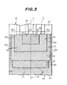
- Fig. 5 is a plan view partly broken away of the tire shown in Fig. 4;
- Fig. 6 is a graph showing a relation between a tensile strain in widthwise direction and an inclination angle B;
- Fig. 7 is a diagrammatically section view of a third embodiment of the pneumatic radial tire according to the invention:
- Fig. 8 is a plan view partly broken away of the tire shown in Fig. 7;
- Fig. 9 is a graph showing a relation between a tensile strain in widthwise direction and an inclination angle C.
- In Figs. 1 and 2,
numeral 11 is a first embodiment of the heavy duty pneumatic radial tire for use in truck and bus according to the invention. Thetire 11 comprises a pair ofbead portions 13, a pair ofsidewall portions 14 extending outward from thesebead portions 13 in a radial direction of the tire, and atread portion 15 of an approximately cylindrical form connecting radially outer ends of thesidewall portions 14 to each other. Further, thetire 11 comprises acarcass 18 toroidally extending between a pair ofbead cores 17 embedded in thebead portions 13 and reinforcing thesidewall portions 14 and thetread portion 15. Each end portion of thecarcass 18 is wound around thebead core 17 provided with astiffener 19 from inside of the tire toward outside thereof. Thecarcass 18 is comprised of at least one rubberized carcass ply, onecarcass ply 20 in this embodiment, which contains manyinextensible cords 21 such as steel cords embedded therein and extending substantially in the radial direction (which are inclined at an angle of 80-90° with respect to an equatorial plane S of the tire). - Numeral 24 is a belt arranged at the outside of the
carcass 18 in the radial direction, which is comprised by laminating at least two belt layers (three belt layers in the illustrated embodiment). Among these belt layers, a maximum-width belt layer 25 having a widest width is arranged at an innermost side in the radial direction, and a narrow-width belt layer 26 having a width somewhat narrower than the width of the maximum-width belt layer 25 is arranged at the outside of the maximum-width belt layer 25 in the radial direction and adjacent thereto, and further a minimum-width belt layer 27 having a width fairly narrower than the width of the narrow-width belt layer 26 is arranged at the outside of the narrow-width belt layer 26 in the radial direction and adjacent thereto. In the threebelt layers cord 28 in the maximum-width belt layer 25 is 18° upward to the right, and the inclination angle of thecord 29 in the narrow-width belt layer 26 is 18° upward to the left, and the inclination angle of thecord 30 in the minimum-width belt layer 27 is 18° upward to the right, and the inclination directions of the cords in these adjoining belt layers are opposite to each other. - In order to mitigate strain concentration between the
belt layers cushion rubber 31 having substantially a triangular shape at a section and a maximum gauge at a widthwise outer end 29a of the narrow-width belt layer 26 is interposed between a widthwise outer end portion of the maximum-width belt layer 25 and a widthwise outer end portion of the narrow-width belt layer 26. - Numeral 32 is a tread arranged at the outside of the
belt 24 in the radial direction. In an outer surface of thetread 32 are formed a plurality ofmain grooves 33 extending in the circumferential direction and many lateral grooves (not shown) crossing with thesemain grooves 33. - Numeral 35 is a pair of reinforcing layers. The reinforcing
layer 35 is arranged so as to overlap with the widthwiseouter end portion 25a of the maximum-width belt layer 25 or a portion of the maximum-width belt layer 25 located outward from the widthwiseouter end 26a of the narrow-width belt layer 26. In the reinforcinglayer 35 are embeddedmany cords 36 slantly arranged with respect to the equatorial plane S and in parallel to each other, in which the inclination direction of thecord 36 is opposite to that of thecord 28 in the maximum-width belt layer 25. - When the reinforcing
layer 35 containingmany cords 36 arranged in a direction opposite to thecords 28 of the maximum-width belt layer 25 is arranged so as to overlap with the widthwiseouter end portion 25a of the maximum-width belt layer 25, the diamond shape defined by thecords 36 of the reinforcinglayer 35 and thecords 28 existing in the widthwiseouter end portion 25a of the maximum-width belt layer 25 is deformed in a crushed form due to the tensional deformation in the circumferential direction at the ground contact region of therunning tire 11. In this case, thereinforcing layer 35, the widthwiseouter end portion 25a of the maximum-width belt layer 25 and rubber surrounding them (including rubber located outward from the widthwiseouter end 26a of the narrow-width belt layer 26 in the widthwise direction) displace inward in the widthwise direction together, so that the tensile strain in the widthwise direction produced at the boundary between the widthwiseouter end 26a of the narrow-width belt layer 26 and the rubber located outward from the widthwiseouter end 26a in the widthwise direction is decreased (or it is a compression strain according to circumstances), whereby the occurrence and development of cracks in the rubber located in the vicinity of ends of thecords 29 in the narrow-width belt layer 26 are effectively controlled. In this way, the belt end separation of the narrow-width belt layer 26 is also prevented effectively. - Moreover, when the outer diameter of the tire is increased during the running for a long time or due to rise of the tire temperature, strain based on the increase of the tire diameter is added to the above strain repeatedly produced during the running in the widthwise
outer end 26a of he narrow-width belt layer 26. In this embodiment, however, such an increase of the tire diameter acts to increase the quantity of displacing the rubber surrounding the widthwiseouter end portion 25a inward in the widthwise direction, so that the belt end separation is further effectively prevented. - When the
cord 36 in the reinforcinglayer 35 is an inextensible cord such as steel cord or aramid cord, the influence of such a cord to thecord 28 embedded in the widthwiseouter end portion 25a becomes larger and the control of the separation failure can be ensured. However, when the reinforcinglayer 35 containing theinextensible cords 36 therein is arranged at the outside of the widthwiseouter end portion 25a in the radial direction, stress concentration occurs in the widthwiseouter end 35a of thereinforcing layer 35 and there is feared the occurrence of separation failure prior to the belt end separation in the widthwiseouter end 26a of the narrow-width belt layer 26. Therefore, it is favorable that when thecord 36 of the reinforcinglayer 35 is the inextensible cord, the reinforcinglayer 35 is closely arranged at the inside of the widthwiseouter end portion 25a of the maximum-width belt layer 25 in the radial direction largely exerting upon the effect of controlling the widthwise deformation through thecarcass 18 as in the illustrated embodiment. - Further, when the
cord 36 of the reinforcinglayer 35 is the inextensible cord, if the width of the reinforcinglayer 35 is made wider, the control of the separation failure can be ensured. However, when the width of the reinforcinglayer 35 is widened so as to locate the widthwiseouter end 35a outward from the widthwiseouter end 25b of the maximum-width belt layer 25, a large tensile strain is created in the widthwiseouter end 35a of the reinforcinglayer 35 and hence there is feared the occurrence of the separation failure at the widthwiseouter end 35a of thereinforcing layer 35 rather than the widthwiseouter end 26a of the narrow-width belt layer 26. Therefore, it is favorable that the widthwiseouter end 35a of the reinforcinglayer 35 is located inward from the widthwiseouter end 25b of the maximum-width belt layer 25 in the widthwise direction as in illustrated embodiment. - In the illustrated embodiment, the width of the reinforcing
layer 35 is narrowed so as to terminate the widthwiseinner end 35b in the vicinity of the widthwiseouter end 26a of the narrow-width belt layer 26. In this case, it is preferable that an inclination angle A of thecord 36 in the reinforcinglayer 35 with respect to the equatorial plane S is within a range of 4-60°, preferably not more than 50°. In the illustrated embodiment, the inclination angle A is 10°. When the inclination angle A is less than 4°, thecords 36 are substantially extended in the circumferential direction and hence the tensile strain in the widthwise direction is hardly reduced in the widthwiseouter end 26a of the narrow-width belt layer 26 as shown in Fig. 3, while when it exceeds 60°, thecords 36 are substantially extended in the widthwise direction and hence the tensile strain in the widthwise direction is hardly reduced in the widthwiseouter end 26a of the narrow-width belt layer 26 as shown in Fig. 3. As the value of the inclination angle A becomes smaller within the above range, the tensile strain in the widthwise direction can be reduced. - The data shown in Fig. 3 are determined by calculation under the following conditions. That is, there is provided a radial tire for truck and bus having a tire size of 11R22.5 and comprising maximum-width, narrow-width and minimum-width belt layers as shown in Figs. 1 and 2, each of which layers containing steel cords of 3 × 0.2 + 6 × 0.38 mm arranged at an end count of 25 cords/5 cm and inclined at the aforementioned angle, and a reinforcing layer containing steel cords of 3 × 0.2 + 6 × 0.38 mm arranged at an end count of 25 cords/5 cm as shown in Figs. 1 and 2, and then the measurement is carried out by applying a load corresponding to the above tire size in load/inflation table of Standards Manual 1998 of The European Tire and Rim Technical Organization. In this case, the widths of the maximum-width, narrow-width and minimum-width belt layers and the reinforcing layer are 180 mm, 150 mm, 80 mm and 20 mm, respectively, and the widthwise outer end of the reinforcing layer is located inward by 7 mm from the widthwise outer end of the maximum-width belt layer in the widthwise direction. Moreover, the tensile strain in widthwise direction in Fig. 3 is represented by an index on the basis that strain produced in the widthwise outer end of the narrow-width belt layer including no reinforcing layer is 1.
- Next, a second embodiment of the invention is described with reference to Figs. 4 and 5. In this embodiment, a reinforcing
layer 38 is comprised of a single layer continued in the widthwise direction by extending each of the reinforcing layers as in the first embodiment inward in the widthwise direction and integrally uniting them at the equatorial plane S in order to enhance the hoop effect of thebelt 24 while simplifying the production. In this case, it is preferable that an inclination angle B of aninextensible cord 39 such as steel cord embedded in the reinforcinglayer 38 is not less than 34°. In this embodiment, the inclination angle B is 52° upward to the left. - When the inclination angle B is less than 34°, a contracting quantity of a
central portion 25c sandwiched between both widthwiseouter end portions 25a in the widthwise direction is increased due to the influence of the reinforcinglayer 38 and hence the tensile strain in the widthwise direction at the widthwiseouter end 26a of the narrow-width belt layer 26 can not effectively be controlled as shown in Fig. 6. - When the reinforcing
layer 38 is arranged at the inside of the maximum-width belt layer 25 in the radial direction, portions of thecords 39 in the reinforcinglayer 38 existing so as to overlap with the widthwiseouter end portion 25a of the maximum-width belt layer 25 act to displace rubber surrounding the widthwiseouter end portion 25a inward in the widthwise direction as mentioned in the first embodiment, while portions of thecords 39 overlapping with thecentral portion 25c of the maximum-width belt layer 25 extend substantially in the widthwise direction so as to serve as a strut bar, whereby the narrowing of the widthwisecentral portion 25c is controlled and hence the tensile strain in the widthwise direction at the widthwiseouter end 26a of the narrow-width belt layer 26 is effectively controlled. When the inclination angle B exceeds 70°, the former effect is hardly expected, but the latter effect increases, so that the tensile strain in the widthwise direction at the widthwiseouter end 26a of the narrow-width belt layer 26 can effectively be controlled even when the inclination angle B finally increases near to 90°. The conditions for the data shown in Fig. 6 are the same as in Fig. 3 except that the width of the reinforcing layer is 165 mm. - Then, a third embodiment of the invention is described with reference to Figs. 7 and 8. In this embodiment, a reinforcing
layer 44 is comprised oforganic fiber cords 45 having a small stiffness instead of the inextensible cord such as steel cord. Since the organic fiber cord is low in the influence upon thecord 28 at the widthwiseouter end portion 25a, if the reinforcinglayer 44 is arranged at the inside of the maximum-width belt layer 25 in the radial direction, rubber located at the outside of the widthwiseouter end portion 25a in the radial direction can not sufficiently be displaced inward in the radial direction. For this end, it is necessary that when thecord 45 is the organic fiber cord, the reinforcinglayer 44 is arranged at the outside of the widthwiseouter end portion 25a in the radial direction to sandwich rubber located at the outside of the widthwiseouter end portion 25a in the radial direction between the widthwiseouter end portion 25a and the reinforcinglayer 44, whereby the influence upon the rubber is enhanced to ensure the displacement inward in the radial direction. - In the illustrated embodiment, since a relatively
thick cushion rubber 31 as previously mentioned is arranged at the outside of the widthwiseouter end portion 25a in the radial direction, the reinforcinglayer 44 is arranged outward at a certain distance from the widthwiseouter end portion 25a in the radial direction, so that the displacement of thecushion rubber 31 inward in the radial direction through the widthwiseouter end portion 25a and the reinforcinglayer 44 becomes small. In the illustrated embodiment, therefore, the widthwise outer end 44a of the reinforcinglayer 44 is located outward from the widthwiseouter end 25a of the maximum-width belt layer 25 in the widthwise direction and the widthwiseinner end 44b of the reinforcinglayer 44 is located at the outside of the narrow-width belt layer 26 in the radial direction and inward from the widthwiseouter end 26a of the narrow-width belt layer 26 in the widthwise direction, whereby the widthwise outer ends 25b, 26a of the maximum-width belt layer 25 and the narrow-width belt layer 26 are covered with the reinforcinglayer 44 so as to largely displace thecushion rubber 31 inward in the radial direction. - In this embodiment, it is favorable that an inclination angle C of the
cord 45 in the reinforcinglayer 44 is not less than 7° with respect to the equatorial plane S of the tire. When the inclination angle C is less than 7°, thecords 45 are extended substantially in the circumferential direction and hence the tensile strain in the widthwise direction at the widthwiseouter end 26a of the narrow-width belt layer 26 can not effectively be controlled as shown in Fig. 9. The conditions for the data shown in Fig. 9 are the same as the conditions for the data shown in Fig. 3 except that the reinforcing layer containing organic fiber cords of nylon-6 (1260 d/2) arranged at an end count of 30 cords/5 cm and inclined at an angle C of 20° with respect to the equatorial plane S is arranged at the outsides of the maximum-width belt layer and the narrow-width belt layer as shown in Figs. 7 and 8 and the widthwise outer end of the reinforcing layer is located outward by 15 mm from the widthwise outer end of the maximum-width belt layer in the widthwise direction and the widthwise inner end thereof is located inward by 30 mm from the widthwise outer end of the narrow-width belt layer in the widthwise direction. In the illustrated embodiment, the widthwise inner end of the reinforcinglayer 44 is extended in the vicinity of the widthwise outer end of the minimum-width belt layer 27 so as to cover the widthwise outer end portion of the narrow-width belt layer from the outside in the radial direction. - In the invention, the reinforcing
layer 44 used in the third embodiment may be added to thetire 11 shown in the first embodiment, or the reinforcinglayer 44 used in the third embodiment may be added to the tire shown in the second embodiment, whereby the belt end separation can more surely be controlled. - There are provided six tires, i.e. a conventional tire wherein the reinforcing layer is omitted from the tire used for the measurement of the data in Fig. 3, a test tire 1 used for obtaining the data of Fig. 3, a test tire 2 used for obtaining the data of Fig. 6, a test tire 3 used for obtaining the data of Fig. 9, a test tire 4 obtained by adding the reinforcing layer of the test tire 3 to the test tire 1, and a test tire 5 obtained by adding the reinforcing layer of the test tire 3 to the test tire 2 for evaluating the resistance to belt end separation. Then, each of these tires is mounted onto a truck and run on general-purpose road including unpaved road over a distance of 70,000 km. Thereafter, the tire is cut to measure a length of crack created in the widthwise outer end of the narrow-width belt layer. When the measured result is represented by an index on the basis that the conventional tire is 100, the index value of the crack length in the test tires 1, 2, 3, 4 and 5 is 50, 30, 55, 28 and 33, respectively. As seen from these results, the belt end separation is effectively controlled in the tires according to the invention.
- As mentioned above, according to the invention, the belt end separation can effectively be prevented in the pneumatic radial tire.
Claims (8)
- A pneumatic radial tire (11) comprising a radial carcass (18) of at least one rubberized cord ply (20) toroidally extending between a pair of bead cores (17), a belt (24) superimposed about a crown portion of the carcass and comprised of at least two belt layers, and a tread (32) arranged at an outside of the belt in a radial direction, in which the belt (24) comprises a maximum-width belt layer (25) containing cords (28) slantly arranged with respect to an equatorial plane (S) of the tire and a narrow-width belt layer (26) arranged at the outside of the maximum-width belt layer in the radial direction and containing cords (29) arranged in an oppositely inclined direction to the cords (28) of the maximum-width belt layer (25), characterized in that a reinforcing layer (35;38;44) containing cords (36;39;45) arranged in an oppositely inclined direction to the cords (28) of the maximum-width belt layer (25) is arranged so as to overlap with an outer end portion (25a) of the maximum-width belt layer (25) located outward from an outer end (26a) of the narrow-width belt layer (26) in the widthwise direction thereof.
- A pneumatic radial tire as claimed in claim 1, characterized in that the cords (36;39) of the reinforcing layer (35;38) are inextensible cords and the reinforcing layer is closely arranged at the inside of the maximum-width belt layer (25) in the radial direction.
- A pneumatic radial tire as claimed in claim 1 or 2, characterized in that the widthwise outer end (35a) of the reinforcing layer (35) is located inward from the widthwise outer end (25b) of the maximum-width belt layer (25) in the widthwise direction.
- A pneumatic radial tire as claimed in any of claims 1 to 3, characterized in that the widthwise inner end (35b) of the reinforcing layer (35) is located in the vicinity of the widthwise outer end (26a) of the narrow-width belt layer (26) and an inclination angle A of the cord (36) embedded in the reinforcing layer (35) with respect to the equatorial plane (S) of the tire is within a range of 4° to 60°.
- A pneumatic radial tire as claimed in claim 1 or 2, characterized in that the reinforcing layer (38) is extended inward in the widthwise direction so as to form a one-piece body on the equatorial plane (S) and an inclination angle B of the cord (39) embedded in the reinforcing layer (38) is not less than 34° with respect to the equatorial plane.
- A pneumatic radial tire as claimed in claim 1, characterized in that the cords (45) of the reinforcing layer (44) are organic fiber cords and the reinforcing layer is arranged at the outside of the maximum-width belt layer (25) in the radial direction.
- A pneumatic radial tire as claimed in claim 6, characterized in that the widthwise inner end (44b) of the reinforcing layer (44) is located at the outside of the narrow-width belt layer (26) in the radial direction and inward from the widthwise outer end (26a) thereof in the widthwise direction, and the widthwise outer end (44a) of the reinforcing layer (44) is located outward from the widthwise outer end (25b) of the maximum-width belt layer (25) in the widthwise direction.
- A pneumatic radial tire as claimed in claim 6 or 7, characterized in that an inclination angle C of the cord (45) embedded in the reinforcing layer (44) is not less than 7° with respect to the equatorial plane (S).
Applications Claiming Priority (2)
| Application Number | Priority Date | Filing Date | Title |
|---|---|---|---|
| JP14224698 | 1998-05-08 | ||
| JP14224698A JP4073081B2 (en) | 1998-05-08 | 1998-05-08 | Pneumatic radial tire |
Publications (3)
| Publication Number | Publication Date |
|---|---|
| EP0955186A2 true EP0955186A2 (en) | 1999-11-10 |
| EP0955186A3 EP0955186A3 (en) | 2001-10-31 |
| EP0955186B1 EP0955186B1 (en) | 2004-07-14 |
Family
ID=15310853
Family Applications (1)
| Application Number | Title | Priority Date | Filing Date |
|---|---|---|---|
| EP99303557A Expired - Lifetime EP0955186B1 (en) | 1998-05-08 | 1999-05-06 | Pneumatic radial tires |
Country Status (5)
| Country | Link |
|---|---|
| US (2) | US6668890B1 (en) |
| EP (1) | EP0955186B1 (en) |
| JP (1) | JP4073081B2 (en) |
| DE (1) | DE69918601T2 (en) |
| ES (1) | ES2224553T3 (en) |
Cited By (4)
| Publication number | Priority date | Publication date | Assignee | Title |
|---|---|---|---|---|
| US7086440B2 (en) * | 2003-11-14 | 2006-08-08 | The Goodyear Tire & Rubber Company | Pneumatic tire with annular reinforcing strip layer |
| FR2887808A1 (en) * | 2005-06-30 | 2007-01-05 | Michelin Soc Tech | PNEUMATIC FOR HEAVY VEHICLES |
| EP3189980A1 (en) * | 2016-01-08 | 2017-07-12 | Continental Reifen Deutschland GmbH | Pneumatic tyres for a vehicle |
| EP3871904A4 (en) * | 2018-10-23 | 2022-08-10 | The Yokohama Rubber Co., Ltd. | Pneumatic tire |
Families Citing this family (9)
| Publication number | Priority date | Publication date | Assignee | Title |
|---|---|---|---|---|
| FR2800673B1 (en) * | 1999-11-08 | 2002-10-18 | Michelin Soc Tech | TOP FRAME FOR RADIAL TIRES |
| DE60209105T2 (en) * | 2001-03-16 | 2006-08-31 | Bridgestone Corp. | TIRE |
| BRPI0511785B8 (en) * | 2004-06-23 | 2018-04-24 | Exxonmobil Upstream Res Co | methods for liquefying a natural gas stream |
| FR2887816A1 (en) * | 2005-06-30 | 2007-01-05 | Michelin Soc Tech | PNEUMATIC FOR HEAVY VEHICLES |
| JP2008024105A (en) * | 2006-07-19 | 2008-02-07 | Bridgestone Corp | Pneumatic radial tire |
| JP2008024104A (en) * | 2006-07-19 | 2008-02-07 | Bridgestone Corp | Pneumatic tire for heavy load |
| KR101375905B1 (en) * | 2006-09-22 | 2014-03-18 | 스미도모 고무 고교 가부시기가이샤 | Heavy duty radial tire |
| US8776854B2 (en) | 2011-08-29 | 2014-07-15 | The Goodyear Tire & Rubber Company | Pneumatic tire with improved crown durability |
| JP5628946B2 (en) * | 2013-02-12 | 2014-11-19 | 株式会社ブリヂストン | Heavy duty tire |
Citations (9)
| Publication number | Priority date | Publication date | Assignee | Title |
|---|---|---|---|---|
| JPS50132604A (en) * | 1974-04-05 | 1975-10-21 | ||
| GB2017019A (en) * | 1978-03-28 | 1979-10-03 | Semperit Ag | Braced-tread radial cord carcass tyre |
| DE3327670A1 (en) * | 1983-07-30 | 1985-02-07 | Continental Gummi-Werke Ag, 3000 Hannover | Pneumatic tyre for a vehicle |
| US4669520A (en) * | 1984-08-24 | 1987-06-02 | Bridgestone Corporation | Heavy duty pneumatic radial tires |
| JPH0367703A (en) * | 1989-08-07 | 1991-03-22 | Bridgestone Corp | Heavy duty pneumatic radial tire |
| LU87862A1 (en) * | 1990-12-18 | 1991-05-07 | Goodyear Tire & Rubber | PNEUMATIC BANDAGE |
| US5111864A (en) * | 1987-12-25 | 1992-05-12 | Bridgestone Corporation | Heavy duty pneumatic radial tires whose belt includes a pair of narrow-width auxiliary protective strips |
| EP0581503A1 (en) * | 1992-07-24 | 1994-02-02 | Bridgestone Corporation | Heavy-duty radial tire |
| EP0698509A2 (en) * | 1994-08-25 | 1996-02-28 | Bridgestone Corporation | Heavy duty pneumatic radial tyres |
Family Cites Families (6)
| Publication number | Priority date | Publication date | Assignee | Title |
|---|---|---|---|---|
| GB1483053A (en) * | 1973-09-22 | 1977-08-17 | Dunlop Ltd | Pneumatic tyres |
| FR2316091A1 (en) * | 1975-06-30 | 1977-01-28 | Uniroyal | PNEUMATIC WHEEL BANDAGE WRAP |
| JPS6144006A (en) * | 1984-08-07 | 1986-03-03 | Bridgestone Corp | Belt construction of radial tire |
| IT1217183B (en) * | 1988-04-22 | 1990-03-14 | Pirelli | MOTORCYCLE TIRE |
| JPH02158403A (en) * | 1988-12-13 | 1990-06-18 | Yokohama Rubber Co Ltd:The | Pneumatic radial-ply tire |
| JPH09207518A (en) * | 1996-02-08 | 1997-08-12 | Sumitomo Rubber Ind Ltd | Air-filled tire |
-
1998
- 1998-05-08 JP JP14224698A patent/JP4073081B2/en not_active Expired - Fee Related
-
1999
- 1999-05-06 DE DE69918601T patent/DE69918601T2/en not_active Expired - Lifetime
- 1999-05-06 ES ES99303557T patent/ES2224553T3/en not_active Expired - Lifetime
- 1999-05-06 EP EP99303557A patent/EP0955186B1/en not_active Expired - Lifetime
- 1999-05-07 US US09/306,634 patent/US6668890B1/en not_active Expired - Fee Related
-
2003
- 2003-10-15 US US10/684,689 patent/US6976518B2/en not_active Expired - Fee Related
Patent Citations (9)
| Publication number | Priority date | Publication date | Assignee | Title |
|---|---|---|---|---|
| JPS50132604A (en) * | 1974-04-05 | 1975-10-21 | ||
| GB2017019A (en) * | 1978-03-28 | 1979-10-03 | Semperit Ag | Braced-tread radial cord carcass tyre |
| DE3327670A1 (en) * | 1983-07-30 | 1985-02-07 | Continental Gummi-Werke Ag, 3000 Hannover | Pneumatic tyre for a vehicle |
| US4669520A (en) * | 1984-08-24 | 1987-06-02 | Bridgestone Corporation | Heavy duty pneumatic radial tires |
| US5111864A (en) * | 1987-12-25 | 1992-05-12 | Bridgestone Corporation | Heavy duty pneumatic radial tires whose belt includes a pair of narrow-width auxiliary protective strips |
| JPH0367703A (en) * | 1989-08-07 | 1991-03-22 | Bridgestone Corp | Heavy duty pneumatic radial tire |
| LU87862A1 (en) * | 1990-12-18 | 1991-05-07 | Goodyear Tire & Rubber | PNEUMATIC BANDAGE |
| EP0581503A1 (en) * | 1992-07-24 | 1994-02-02 | Bridgestone Corporation | Heavy-duty radial tire |
| EP0698509A2 (en) * | 1994-08-25 | 1996-02-28 | Bridgestone Corporation | Heavy duty pneumatic radial tyres |
Non-Patent Citations (1)
| Title |
|---|
| PATENT ABSTRACTS OF JAPAN vol. 015, no. 225 (M-1122), 10 June 1991 (1991-06-10) & JP 03 067703 A (BRIDGESTONE CORP), 22 March 1991 (1991-03-22) * |
Cited By (7)
| Publication number | Priority date | Publication date | Assignee | Title |
|---|---|---|---|---|
| US7086440B2 (en) * | 2003-11-14 | 2006-08-08 | The Goodyear Tire & Rubber Company | Pneumatic tire with annular reinforcing strip layer |
| FR2887808A1 (en) * | 2005-06-30 | 2007-01-05 | Michelin Soc Tech | PNEUMATIC FOR HEAVY VEHICLES |
| WO2007003557A1 (en) * | 2005-06-30 | 2007-01-11 | Société de Technologie Michelin | Tyre for heavy vehicles |
| US8291951B2 (en) | 2005-06-30 | 2012-10-23 | Michelin Recherche Et Technique S.A. | Tire for heavy vehicles |
| EP3189980A1 (en) * | 2016-01-08 | 2017-07-12 | Continental Reifen Deutschland GmbH | Pneumatic tyres for a vehicle |
| EP3871904A4 (en) * | 2018-10-23 | 2022-08-10 | The Yokohama Rubber Co., Ltd. | Pneumatic tire |
| EP4194227A1 (en) * | 2018-10-23 | 2023-06-14 | The Yokohama Rubber Co., Ltd. | Pneumatic tire |
Also Published As
| Publication number | Publication date |
|---|---|
| DE69918601D1 (en) | 2004-08-19 |
| US20040079463A1 (en) | 2004-04-29 |
| EP0955186A3 (en) | 2001-10-31 |
| US6668890B1 (en) | 2003-12-30 |
| US6976518B2 (en) | 2005-12-20 |
| JP4073081B2 (en) | 2008-04-09 |
| ES2224553T3 (en) | 2005-03-01 |
| EP0955186B1 (en) | 2004-07-14 |
| DE69918601T2 (en) | 2005-07-28 |
| JPH11321230A (en) | 1999-11-24 |
Similar Documents
| Publication | Publication Date | Title |
|---|---|---|
| EP0628435B1 (en) | Pneumatic motorcycle tyre | |
| US5435369A (en) | Truck tire with split overlay | |
| JP3645277B2 (en) | Pneumatic tire | |
| GB2132574A (en) | Pneumatic radial tire and method of manufacturing the same | |
| JP3942649B2 (en) | Heavy duty radial tire | |
| US6668890B1 (en) | Pneumatic radial tires | |
| JPH0133362B2 (en) | ||
| US20100282391A1 (en) | Pneumatic tire | |
| CN101213086A (en) | Tyre for heavy vehicle | |
| KR100573196B1 (en) | Radial tyre top reinforcement | |
| CN101213096B (en) | Tyre for heavy vehicle | |
| JPS64241B2 (en) | ||
| US8763664B2 (en) | Reinforcement comprising two reinforcing materials and tire comprising such a reinforcement | |
| JP2007015638A (en) | Pneumatic tire | |
| EP0317487B1 (en) | Radial-ply pneumatic tire with reverse curvature carcass ply | |
| EP2724872A1 (en) | Motorcycle pneumatic tire | |
| EP0987129B1 (en) | Pneumatic radial tires | |
| AU725389B2 (en) | Crown reinforcement for a tyre | |
| JPS63151504A (en) | Pneumatic radial tyre | |
| JP4939681B2 (en) | Heavy duty pneumatic radial tire | |
| JP3338486B2 (en) | Pneumatic tire | |
| EP0865942B1 (en) | Heavy duty pneumatic radial tyres | |
| JP4691256B2 (en) | Tread support membrane | |
| US5078191A (en) | Off-the-road heavy duty pneumatic radial tires for decreasing inner rubber peeling and cracking in the vicinity of the shoulder portion | |
| JP4230581B2 (en) | Heavy duty pneumatic radial tire |
Legal Events
| Date | Code | Title | Description |
|---|---|---|---|
| PUAI | Public reference made under article 153(3) epc to a published international application that has entered the european phase |
Free format text: ORIGINAL CODE: 0009012 |
|
| AK | Designated contracting states |
Kind code of ref document: A2 Designated state(s): AT BE CH CY DE DK ES FI FR GB GR IE IT LI LU MC NL PT SE Kind code of ref document: A2 Designated state(s): DE ES FR GB IT |
|
| AX | Request for extension of the european patent |
Free format text: AL;LT;LV;MK;RO;SI |
|
| PUAL | Search report despatched |
Free format text: ORIGINAL CODE: 0009013 |
|
| AK | Designated contracting states |
Kind code of ref document: A3 Designated state(s): AT BE CH CY DE DK ES FI FR GB GR IE IT LI LU MC NL PT SE |
|
| AX | Request for extension of the european patent |
Free format text: AL;LT;LV;MK;RO;SI |
|
| 17P | Request for examination filed |
Effective date: 20020204 |
|
| AKX | Designation fees paid |
Free format text: DE ES FR GB IT |
|
| 17Q | First examination report despatched |
Effective date: 20030514 |
|
| GRAP | Despatch of communication of intention to grant a patent |
Free format text: ORIGINAL CODE: EPIDOSNIGR1 |
|
| GRAS | Grant fee paid |
Free format text: ORIGINAL CODE: EPIDOSNIGR3 |
|
| GRAA | (expected) grant |
Free format text: ORIGINAL CODE: 0009210 |
|
| AK | Designated contracting states |
Kind code of ref document: B1 Designated state(s): DE ES FR GB IT |
|
| REG | Reference to a national code |
Ref country code: GB Ref legal event code: FG4D |
|
| REF | Corresponds to: |
Ref document number: 69918601 Country of ref document: DE Date of ref document: 20040819 Kind code of ref document: P |
|
| ET | Fr: translation filed | ||
| REG | Reference to a national code |
Ref country code: ES Ref legal event code: FG2A Ref document number: 2224553 Country of ref document: ES Kind code of ref document: T3 |
|
| PLBE | No opposition filed within time limit |
Free format text: ORIGINAL CODE: 0009261 |
|
| STAA | Information on the status of an ep patent application or granted ep patent |
Free format text: STATUS: NO OPPOSITION FILED WITHIN TIME LIMIT |
|
| 26N | No opposition filed |
Effective date: 20050415 |
|
| PGFP | Annual fee paid to national office [announced via postgrant information from national office to epo] |
Ref country code: ES Payment date: 20070524 Year of fee payment: 9 |
|
| PGFP | Annual fee paid to national office [announced via postgrant information from national office to epo] |
Ref country code: GB Payment date: 20070502 Year of fee payment: 9 |
|
| PGFP | Annual fee paid to national office [announced via postgrant information from national office to epo] |
Ref country code: IT Payment date: 20070507 Year of fee payment: 9 |
|
| GBPC | Gb: european patent ceased through non-payment of renewal fee |
Effective date: 20080506 |
|
| PG25 | Lapsed in a contracting state [announced via postgrant information from national office to epo] |
Ref country code: GB Free format text: LAPSE BECAUSE OF NON-PAYMENT OF DUE FEES Effective date: 20080506 |
|
| REG | Reference to a national code |
Ref country code: ES Ref legal event code: FD2A Effective date: 20080507 |
|
| PG25 | Lapsed in a contracting state [announced via postgrant information from national office to epo] |
Ref country code: IT Free format text: LAPSE BECAUSE OF NON-PAYMENT OF DUE FEES Effective date: 20080506 |
|
| PG25 | Lapsed in a contracting state [announced via postgrant information from national office to epo] |
Ref country code: ES Free format text: LAPSE BECAUSE OF NON-PAYMENT OF DUE FEES Effective date: 20080507 |
|
| PGFP | Annual fee paid to national office [announced via postgrant information from national office to epo] |
Ref country code: DE Payment date: 20120502 Year of fee payment: 14 |
|
| PGFP | Annual fee paid to national office [announced via postgrant information from national office to epo] |
Ref country code: FR Payment date: 20120608 Year of fee payment: 14 |
|
| PG25 | Lapsed in a contracting state [announced via postgrant information from national office to epo] |
Ref country code: DE Free format text: LAPSE BECAUSE OF NON-PAYMENT OF DUE FEES Effective date: 20131203 |
|
| REG | Reference to a national code |
Ref country code: DE Ref legal event code: R119 Ref document number: 69918601 Country of ref document: DE Effective date: 20131203 |
|
| REG | Reference to a national code |
Ref country code: FR Ref legal event code: ST Effective date: 20140131 |
|
| PG25 | Lapsed in a contracting state [announced via postgrant information from national office to epo] |
Ref country code: FR Free format text: LAPSE BECAUSE OF NON-PAYMENT OF DUE FEES Effective date: 20130531 |