JP4691256B2 - Tread support membrane - Google Patents
Tread support membrane Download PDFInfo
- Publication number
- JP4691256B2 JP4691256B2 JP2000583728A JP2000583728A JP4691256B2 JP 4691256 B2 JP4691256 B2 JP 4691256B2 JP 2000583728 A JP2000583728 A JP 2000583728A JP 2000583728 A JP2000583728 A JP 2000583728A JP 4691256 B2 JP4691256 B2 JP 4691256B2
- Authority
- JP
- Japan
- Prior art keywords
- ply
- reinforcing
- side wall
- crown
- reinforcement
- Prior art date
- Legal status (The legal status is an assumption and is not a legal conclusion. Google has not performed a legal analysis and makes no representation as to the accuracy of the status listed.)
- Expired - Fee Related
Links
Images


Classifications
-
- B—PERFORMING OPERATIONS; TRANSPORTING
- B60—VEHICLES IN GENERAL
- B60C—VEHICLE TYRES; TYRE INFLATION; TYRE CHANGING; CONNECTING VALVES TO INFLATABLE ELASTIC BODIES IN GENERAL; DEVICES OR ARRANGEMENTS RELATED TO TYRES
- B60C17/00—Tyres characterised by means enabling restricted operation in damaged or deflated condition; Accessories therefor
- B60C17/01—Tyres characterised by means enabling restricted operation in damaged or deflated condition; Accessories therefor utilising additional inflatable supports which become load-supporting in emergency
- B60C17/02—Tyres characterised by means enabling restricted operation in damaged or deflated condition; Accessories therefor utilising additional inflatable supports which become load-supporting in emergency inflated or expanded in emergency only
-
- Y—GENERAL TAGGING OF NEW TECHNOLOGICAL DEVELOPMENTS; GENERAL TAGGING OF CROSS-SECTIONAL TECHNOLOGIES SPANNING OVER SEVERAL SECTIONS OF THE IPC; TECHNICAL SUBJECTS COVERED BY FORMER USPC CROSS-REFERENCE ART COLLECTIONS [XRACs] AND DIGESTS
- Y10—TECHNICAL SUBJECTS COVERED BY FORMER USPC
- Y10T—TECHNICAL SUBJECTS COVERED BY FORMER US CLASSIFICATION
- Y10T152/00—Resilient tires and wheels
- Y10T152/10—Tires, resilient
- Y10T152/10495—Pneumatic tire or inner tube
- Y10T152/10522—Multiple chamber
- Y10T152/10576—Annular chambers
- Y10T152/10594—Mutually free walls
Abstract
Description
【0001】
(技術分野)
本発明はタイヤのトレッド用の支持手段に関する。上記支持手段は上記タイヤとその取付けリムとで、車両用の走行組立体を構成しており、この走行組立体はタイヤの必然的な予期しない圧力損失後に走行することができ、上記タイヤは特に重車両のチューウブレス型または土木工学型である。
【0002】
(背景技術)
フランス出願第FR2756221号はタイヤのキャビティの圧力P1より大きい圧力P0まで膨らまされる補強ゴム製の環状面形膜をトレッド用支持手段として述べ、且つ請求しており、この環状面形膜は膨らまし状態で、推薦圧力で使用されるタイヤの負荷半径REより小さいクラウン半径RMを有し、上記膜は少なくともそのクラウンにおいて、コードまたはケーブルよりなる少なくとも1つの層により補強されており、上記膜の上記クラウンは更に周方向配向のコードまたはケーブルよりなる少なくとも1つのたが嵌め補強体を備えており、このたが嵌め補強体はクラウン半径RMと表面1cmあたりの圧力との積に少なくとも等しい層1cmあたりの破断荷重を有し、その結果、層1cmあたりの張力はタイヤが受けることができる最大の遠心力に起因した張力と同等になり、タイヤが受ける圧力損失の場合に存在し、初めの差圧P0−P1より大きい差圧P0−P'1の場合、すなわち、通常走行中、たが嵌めコードまたはケーブルの破断を許容する。上記たが嵌め補強体は一般にクラウン補強層間に位置決めされた少なくとも1つの層で構成されるか、或いは下層を半径方向に覆う保護層または指示バンドに形成された凹部に位置決めされたいくつかのバンドで構成されている。
【0003】
低温状態、すなわち、20℃で測定した上記膜の内圧は、関係するタイヤの寸法に応じて、0.5x10⁵Paと5.0x10⁵Paとの間の量だけタイヤの内キャビティの圧力P1より大きい。環状面形膜のクラウン半径RMが好ましくはタイヤの負荷半径REの0.80倍と0.97倍との間にあると仮定すると、主のタイヤの加熱の理由で、高すぎる差圧により、タイヤ自身の或る数の特性、例えば、過剰に大きいたが嵌め補強体を必要としながら、タイヤのカーカス補強体の寿命に悪影響する恐れがある。
【0004】
上記膜のクラウンは好ましくは、各々において互いに平行であり、1つから次まで交差されて周方向と50°と85°との間の角度をなすコードまたはケーブルよるなり2つの層により補強されている。ケーブルまたはコードは有利には軽さ、可撓性および良好な耐腐食性の理由で織物であり、好ましくは芳香族ポリアミド製である。2つの層の軸方向端部は好ましくは、Sがタイヤのカーカス補強体の最大の軸方向幅であるとすると、層の幅が好ましくはSと1.30Sとの間であるように、膜の側壁部に位置決めされている。
【0005】
差圧P0−P1は、タイヤがパンクし、且つたが嵌め層が判断した場合に増大し、環状面形支持膜はタイヤのキャビティの中へ伸張し、タイヤのキャビティ内の圧力降下にかかわらず、全体が走行し続けることが可能である。
【0006】
上記フランス特許出願に記載の発明による環状面形支持膜は各々が半径芳香のコードまたはケーブルよりなる少なくとも1つの層により補強された側壁部を備えてもよく、これらの側壁部は有利にはタイヤの金属取付けリムに開口する半径方向溝を備えている。
【0007】
タイヤ、その取付けリムおよび膜のより構成された組立体の通常の走行条件下、このタイヤに薦められる負荷条件、圧力条件および速度条件下で、膜は実際に一定であってタイヤの負荷半径より小さい赤道半径を保持し、側壁部の外壁部は大部分がタイヤの内壁部と永久接触している。上記壁部間に存在する摩擦の結果、タイヤの内壁部を覆う不透過性ゴム層が早期に劣化し、磨耗する。
【0008】
上記欠点を解消するために、フランス特許出願第97/16450号は、膜に特定の側壁構成を与えることを提案している。すなわち、構成によりたが嵌め層の破断後に破断を許容する環状補強要素のまわりに側壁部補強層がいずれかの側で巻かれており、上記側壁部補強層は、膨らまし状態では、或る高さ以降、膜と最も近い側壁部の内壁部との間に接触が無いようになっている子午線輪郭を有する。換言すると、環状補強要素の存在により、膨らまし状態で且つ通常の走行中、タイヤキャビティ内の圧力損失時に支持膜の通常の完全伸張を妨げないで、側壁補強層の所望の子午線輪郭を維持することが可能である。
【0009】
膜の側壁補強層の環状要素または巻きつけビードワイヤの存在により、下記の2つの主な欠点が生じる。
【0010】
− 破断後にビードワイヤの切片の位置を制御することは不可能とは言わないが困難であり、かくして、特に、赤道平面に対する伸張後の膜のクラウンの位置決めの目立った非対称が非常に頻繁に見られ、これにより装備した車両に或る駆動問題を引き起こしていた。
【0011】
− いわゆる閉鎖支持膜(この膜の横断面は連続した外形を有する)の場合、巻きつけビードワイヤの破断は上記ビードワイヤの下に半径方向に位置決めされた膜部分の大きい伸張を引き起こし、その結果、上記部分が破断し、上記膜から膨らましガスが逃げる。
【0012】
上記欠点を解消するために、第1に、タイヤキャビティの膨らまし圧が消去されるときにタイヤのキャビティを埋めることが可能な伸張可能な環状面形膜の原理、第2に、通常の走行の場合に膜とタイヤの内壁部との間の最も低い可能性の接触長さの原理と保持しながら、本発明による補強ゴム膜は、
− タイヤP用のトレッド支持手段として使用され、上記タイヤPと、呼称直径がDSであり、フランジが外径DRを有するタイヤの取付けリムJとともに、タイヤが圧力損失を受けると、走行することが可能である走行組立体を構成し、
− タイヤのキャビティの圧力P1より大きい圧力P0まで膨らまされ、
− 膨らまし状態で、推薦圧力で使用されるタイヤの負荷半径REより小さいクラウン半径RMを有し、
− クラウンにおいて、各々において互いに平行であり、且つ1つから次まで交差されているコードまたはケーブルよりなる少なくとも2つの層により補強されており、上記層の少なくとも一方は、コードまたはケーブルよりなる少なくとも1つの層で構成されており、且つ第1に、通常走行中に存在する差圧P0−P1に起因して張力により増大されたタイヤが受ける最大の遠心力による張力、第2に、P0−P1より大きい差圧P0−P'1のためのコードまたはケーブルの破断を阻止することを可能にする層1cmあたりの破断荷重を有する所謂たが嵌め層であり、
− 少なくとも1つの層により側壁部の各々において補強されている。本発明によるこの補強ゴム膜は、子午線断面で見て、以下の点を特徴としている。
【0013】
− 側壁補強層は側壁層の作用により誘発される張力の作用下で破断しない伸張不可能な環状補強要素のまわりに巻くことによって側壁部の各下部分に固定され、上記環状補強要素の内径Dは値DRと、リム座部の幅LSと上記座部の傾斜角のタンジェントとの積をDSから引いた値との間であり、
― 上記側壁補強層は補強要素で構成されており、各要素は螺旋状に巻かれたコードまたはケーブルにより取囲まれたコアを備えており、上記コアは、第1に、差圧P0−P1および上記要素が受ける最大の遠心力に起因して層の各要素あたり張力より大きく、且つ第2に、P0−P1より大きい差圧P0−P'1の場合で、たが嵌め層の要素の破断後、側壁層の上記要素の破断を許容する程度の破断荷重を有しており、
― 側壁層の上記補強要素は、コアの破断伸び率aAより大きい伸び率の場合、伸び率の関数としての牽引力の変化が実質的にゼロであるセグメントを有する相対伸び率aの関数としての張力を表す曲線を有しており、
− 補強要素の破断伸び率aRは膜の外側子午線長さに対するタイヤの内側子午線長さと膜の外側子午線長さとの差の比に少なくとも等しい。
【0014】
好ましくは、伸張不可能な補強要素の内径Dは値DSと、リム座部の幅LSと上記座部の傾斜角度のタンジェントとの積をDSから引いた値との間にある。
【0015】
膜のクラウンはクラウンのところの上記層の存在が効果的であるときに層により補強されると言える。膜の側壁部は側壁部に実際に層が存在するなら、層により補強されると言え、かくして、2つの膜ビードワイヤに固定された層は側壁補強層であるだけではなく、クラウン補強層でもある。
【0016】
(発明を実施するための最良の形態)
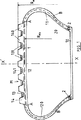
本発明による環状面形膜Mは、第1例(図1)では、そのクラウン(1)が閉じられ、且つ補強されている。この膜は、その薄い厚さがその半径方向内側部分(10)にわたって一定であるが、その側壁部(11)およびそのクラウン(1)のところで厚くなっている。膜は2つの層(120)により全体的に補強されており、各層は、互いに平行であり、且つ集成体の赤道線XX'と50°と85°との間の角度、より正確には60°に等しい角度をなしている補強要素で構成されており、この角度は層の一方では一方向で、他方の層では反対方向のものである。2つの層(120)各々の幅はその端部の一方が膜Mの肩部のうちの一方の領域に位置決めされ、層(120)の他端部Bが、上記肩部と反対の側に位置決めされた膜側壁部の下部分において環状の補強要素(2)のまわりに巻いた後に形成する上向き部(20)の端部であるような幅である。従って、2つの層(20)は、膜Mのクラウンの領域AAにおいて、各々において互いに平行であり、1つから次まで交差されて、赤道方向と60°の角度をなす要素の2つのクラウン補強層の機能を果たし、また側壁部の領域ABにおいて側壁補強層の機能を果たし、各側壁部は赤道方向と90°より小さく且つ赤道平面で測定した角度より大きい可変角度をなす要素層で補強されている。
【0017】
容易に伸張可能であるかくして形成された2つのクラウン層(120)の集成体(12)上には、凹部‘141)により互いにから分離された截頭円錐形浮彫り要素(140)を備えたゴム支持バンド(14)が設けられるのがよい。これらの截頭円錐形「ブロック」はブロック(140)の2つの軸方向隣接列間に芳香族ポリアミド製の3本のコードで構成された周ケーブルよりなるたが嵌めストリップ(131)が配置されるようにバンド(14)の表面に周方向の列を構成する。かくして構成され且つたが嵌め集成体(13)を構成する3本の周ケーブル(それらの数はブロック(140)の列間の軸方向ギャップの数に等しい)よりなるストリップ(131)よりなる集成体は、第1に遠心力に起因する力に抗して、第2に差圧p0−p1(p0は10x105Paに等しい環状面形膜Mの膨らまし圧力であり、p1は9.0x10⁵Paに等しいタイヤPの圧力である)に起因する力に抗して膜Mをたが嵌めする機能を果たす。上記たが嵌め機能により、集成体の通常の走行条件下、すなわち、このタイヤ用に薦められる負荷、圧力および速度条件下で、膜Mおよびそのクラウン層が通常の走行条件下で実際に一定であり且つタイヤPの負荷半径REより小さいそれぞれの半径RM、RM1を保持することが可能である。
【0018】
各環状要素は167x2のポリアミド製ケーブルを巻くことによって構成されている。このような組成物は側壁層の補強要素の環状要素に及ぼされる必要な強さの少なくとも1.05倍の引張り強さおよび事実上完全な伸張性を上記環状要素に与え、かくして環状要素(2)は上記条件下でできるだけタイヤの取付けリムに半径方向に近接して配置され、図示の場合、その内径はリムの呼称直径DSと値DSマイナス積LS x tan aとの間である(LSはタイヤビード座部の軸方向幅であり、tan aは取付けリムの座部の傾斜角度のタンジェントである)。
【0019】
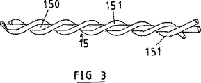
側壁およびクラウン補強層(120)の各補強要素(15)(図3)は122x1レーヨン補強要素で形成されているコア(150)で構成されている。このコアは7.5%の相対伸び率ε A の場合に6.2daNの破壊荷重FRAを有する(図4)(曲線の点Mは相対伸び率の関数としての力を表している。上記コアのまわりには、167テックスのコード(151)が巻かれており、各コード(151)がそれ自身に撚られており、2本のコードがコア(150)のまわりに撚られている。破断コア要素と称するかくして得られた補強要素(15)はコア(150)の破断時の伸び率ε A よりはるかに大きい90%の破断伸び率ε R (曲線上の点R)を有しており、従って、上記コアの破断後、補強要素(15)はそれ自身が破断する前の高い伸びポテンシャルを有し(曲線の部分NR)、上記ポテンシャルは80%より大きいと推定される。上記ポテンシャルは、タイヤキャビティが充填されるまで、膜の完全な伸張を許容するのに非常に十分である。何故なら、必要十分な伸び率が膜の外側子午線長さに対するタイヤの内側子午線長さと膜の外側子午線長さとの差の比に等しいからであり、上記長さはビードワイヤからビードワイヤまで測定したものである。
【0020】
先に考察した場合では、たが嵌めバンド(131)の周方向補強要素は或る差圧P0−P'1で破断する。層(120)用に使用した要素(15)の構造と同様な構造を有する補強要素をたが嵌めバンド用の補強要素として使用することが含まれず、本発明の範囲から逸脱することは明らかである。例えば、各たが嵌め要素は110x1の芳香族ポリアミド製コアと、上記コアのまわりに巻かれた167x2の2本の芳香族ポリアミド製ケーブルとで構成されている。たが嵌め要素のコアは圧力P1を下げた結果の支持張力で破断する一方、全体要素は破断しないが、非常に伸張性になる。この解決法によれば、ストリップの部片が破断した後、実質的に高い材料コストを犠牲にしてストリップの部片の分散をできるだけ回避することが可能である。
【0021】
図2において、組立体Eは上記例では寸法495/45―R―22.5のタイヤPと、取付けリムJと、本発明による環状面形膜Mとで構成されている。タイヤPは一般に公知なタイヤであり、側壁部が外側でトレッド(21)に半径方向に接合され、且つ内側で2つのビード(22)に半径方向に延長されており、各ビード(22)は、ラジアルカーカス補強体(24)がまわりに固定されて上向き部(25)を構成している少なくとも1本のビードワイヤ(23)により補強されている。上記カーカス補強体(24)上には、クラウンにおいて、金属コードまたはケーブルよりなる少なくとも2つの層で構成されたクラウン補強体(26)が設けられており、このクラウン補強体(26)は各層において互いにに平行であり、1つの層から次の層まで交差されて周方向と5°と45°との間であるのがよい角度を成している。タイヤPはチューブレスと称し、膨らましガスに対して不透過性であるゴム混合物よりなる層を内側に備えている。
【0022】
図5は支持膜の最も簡単な構成を示しており、クラウンおよび上記膜の側壁部は1つの平面内に見られる。側壁部(11)は半径方向以外は上記のものと同じ組成の破断コア補強要素(15)の単一の半径方向層(120)により補強されている。上記膜のクラウン(1)は支持バンド(14)の下に半径方向に配置されたたが嵌め層(13)により相補的に補強されており、上記たが嵌め層は層1cmあたりの破断荷重がタイヤのキャビティの膨らまし圧P1の一次関数であるように補強要素で構成されており、代表的な直線の角度係数は0.05に等しく、上記直線の原点における座標は0.3x10⁵Paに等しく、タイヤは「重車両」型タイヤである。クラウンは有利には、平面内でうねっていて、互いに平行であり、0°90°との間であるのがよい角度に周方向に対して配向された金属補強要素よりなる少なくとも1つの層により、たが嵌め層の外側まで半径方向に完全に補強されており、うねりの振幅および波長は明らかに膜の半径方向伸張を妨げないように選択される。
【0023】
図6は2つの層(120)を有する膜の組織を示しており、これらの層は、ビードワイヤ(2)からビードワイヤ(2)まで連続しており、上記のものと同じ組成の破断コア補強要素(15)で構成されが、1つの層から次の層まで交差されて膜の赤道平面で測定して50°と85°との間、より正確には、60°に等しい角度を周方向となしている。これらの2つの層(120)は側壁補強層およびクラウン補強層であり、クラウンは図5に示し且つ先に説明したようにたが嵌め層(13)により相補的に補強されている。
【0024】
図7に示す組織は、ビードワイヤ(2)からビードワイヤ(2)まで連続しているので、側壁/クラウン補強層(120)を備えており、この層(120)は先のものと同じ破断コア要素で構成されており、これらの要素は層において互いに平行であり、膜のクラウンのところで測定して周方向と60°(できれば、50°と85°との間)の角度をなしている。層(120)のものと同じ補強要素補強要素で構成された所定の軸方向幅のクラウン層(121)がクラウンにおける層(120)上に半径方向に設けられており、このクラウン層(121)は層(120)と交差されて周方向に対して同じ反対方向の角度をなしている。層(121)上には、凹部(141)により間隔を隔てられた截頭円錐形浮彫り要素(140)を備えた支持ストリップ(14)が半径方向に設けられてもよい。これらの截頭円錐形「ブロック」はトレッド(14)の表面に周方向列を構成し、集成体がたが嵌め層(13)を構成する周方向ケーブルよりなるたが嵌めストリップ(131)がブロック(140)の2つの軸方向隣接列間に配置されるようになっている。また、層(121)には、図5に示して図5に対応する節で述べたもののようなたが嵌め層がより簡単に設けられてもよい。
【図面の簡単な説明】
【図1】 本発明による環状面形支持膜の図である。
【図2】 作動時に設けられ、膨らまされたタイヤに適所にある図1の膜の図である。
【図3】 膜の側壁補強層用に使用される補強要素の図である。
【図4】 側壁補強層の補強要素の相対伸び率の関数としての張力を示す曲線である。
【図5】 本発明による支持膜の変形例の図である。
【図6】 本発明による支持膜の変形例の図である。
【図7】 本発明による支持膜の変形例の図である。[0001]
(Technical field)
The present invention relates to a support means for a tire tread. The supporting means comprises the tire and its mounting rim to form a traveling assembly for a vehicle, which traveling assembly can travel after the inevitably unexpected pressure loss of the tire, It is a heavy-duty chewless type or civil engineering type.
[0002]
(Background technology)
French application No. FR 2756221 describes and claims a reinforcing rubber annular surface membrane which is inflated to a pressure P 0 which is greater than the pressure P1 of the tire cavity, as a means for supporting the tread, and this annular surface membrane is inflated. The tire has a crown radius R M smaller than the load radius R E of the tire used at the recommended pressure, and the membrane is reinforced at least in its crown by at least one layer of cords or cables, The crown further comprises at least one leg-fit reinforcement comprising a circumferentially oriented cord or cable, which is at least equal to the product of the crown radius RM and the pressure per cm surface. Has a breaking load per cm of layer, so that the tension per cm of layer is the maximum centrifugal force that the tire can receive Present in the case of a pressure loss experienced by the tire, and in the case of a differential pressure P 0 -P ' 1 greater than the initial differential pressure P 0 -P 1 , i.e. Allows breakage of mating cord or cable. The above-mentioned reinforcements are generally composed of at least one layer positioned between crown reinforcing layers, or several bands positioned in a recess formed in a protective layer or indicating band that radially covers the lower layer It consists of
[0003]
The inner pressure of the membrane measured at low temperature,
[0004]
The crowns of the membrane are preferably parallel to each other and reinforced by two layers of cords or cables crossing from one to the next and forming an angle between the circumferential direction and 50 ° and 85 °. Yes. The cable or cord is advantageously woven for reasons of lightness, flexibility and good corrosion resistance, preferably made of aromatic polyamide. The axial ends of the two layers are preferably such that the width of the layers is preferably between S and 1.30S, where S is the maximum axial width of the carcass reinforcement of the tire. It is positioned on the side wall portion.
[0005]
The differential pressure P 0 -P 1 increases when the tire punctures and the fit layer determines, and the annular planar support membrane extends into the tire cavity, resulting in a pressure drop within the tire cavity. Regardless, the whole can continue to run.
[0006]
The annular planar support membrane according to the invention described in the above-mentioned French patent application may comprise side walls reinforced by at least one layer each consisting of a radial scented cord or cable, these side walls advantageously being a tire A radial groove opening in the metal mounting rim.
[0007]
Under normal driving conditions of the assembly consisting of the tire, its mounting rim and the membrane, under the recommended load, pressure and speed conditions for this tire, the membrane is actually constant and less than the tire's load radius. A small equator radius is maintained, and the outer wall portion of the side wall portion is in permanent contact with the inner wall portion of the tire. As a result of the friction existing between the wall portions, the impermeable rubber layer covering the inner wall portion of the tire is deteriorated and worn out at an early stage.
[0008]
In order to overcome the above disadvantages, French patent application No. 97/16450 proposes to give the membrane a specific sidewall configuration. That is, the side wall portion reinforcing layer is wound on either side around the annular reinforcing element that allows breakage after the fitting layer breaks, and the side wall portion reinforcing layer has a certain height in the expanded state. From then on, the meridian contour is such that there is no contact between the membrane and the inner wall of the nearest side wall. In other words, the presence of the annular reinforcing element maintains the desired meridian profile of the side wall reinforcement layer without inflating the normal full stretch of the support membrane during inflated and normal running and during pressure loss in the tire cavity. Is possible.
[0009]
The presence of the annular element of the membrane sidewall reinforcement layer or the wound bead wire causes two main drawbacks:
[0010]
-It is difficult, if not impossible, to control the position of the bead wire section after rupture, and in particular, a marked asymmetry in the positioning of the membrane crown after stretching relative to the equator plane is very often seen. This has caused certain drive problems in the equipped vehicles.
[0011]
-In the case of so-called closed support membranes (the cross section of this membrane has a continuous profile), the breakage of the wound bead wire causes a large stretch of the membrane part positioned radially under the bead wire, so that The part breaks and the gas swells away from the membrane.
[0012]
In order to eliminate the above drawbacks, firstly, the principle of an extensible annular surface membrane that can fill the tire cavity when the inflation pressure of the tire cavity is eliminated, secondly, the normal running Reinforcing rubber membranes according to the present invention, while retaining the principle of the lowest possible contact length between the membrane and the inner wall of the tire,
- used as a tread support means for a tire P, a said tire P, the nominal diameter is D S, flange with mounting rim J of the tire having an outer diameter D R, the tire is subjected to pressure loss, running Comprises a traveling assembly that is capable of
-Inflated to a pressure P0 greater than the pressure P1 in the tire cavity;
-In the inflated state, having a crown radius R M smaller than the load radius R E of the tire used at the recommended pressure;
The crown is reinforced by at least two layers of cords or cables that are parallel to each other and crossed from one to the next, at least one of the layers being at least one of cords or cables First , the tension caused by the maximum centrifugal force that the tire increased by tension due to the differential pressure P 0 -P 1 existing during normal driving, second, P 0 -P was 1 called with a larger pressure difference P 0 -P 'code or breaking load per layer 1cm that allows to prevent breakage of the cables for the 1 but is fitted layer,
It is reinforced in each of the side walls by at least one layer. This reinforced rubber film according to the present invention is characterized by the following points as seen in the meridian section.
[0013]
The side wall reinforcing layer is secured to each lower part of the side wall by winding it around a non-stretchable annular reinforcing element that does not break under the action of the tension induced by the action of the side wall layer; is between the value D R, the value of the product drawn from D S of the tangent of the inclination angle of the width L S and the seat portion of the rim seat,
-The side wall reinforcing layer is composed of reinforcing elements, each element comprising a core surrounded by a spirally wound cord or cable, said core firstly having a differential pressure P 0- In the case of a differential pressure P 0 -P ′ 1 greater than the tension per element of the layer and secondly greater than P 0 -P 1 due to P 1 and the maximum centrifugal force experienced by the element, After the breakage of the element of the fitting layer, it has a breaking load to the extent that allows the breakage of the element of the sidewall layer,
-The reinforcing element of the side wall layer is a function of relative elongation a as a function of the elongation having a segment with substantially no change in tractive force as a function of elongation for elongations greater than the breaking elongation a A of the core. Has a curve representing the tension,
The elongation at break a R of the reinforcing element is at least equal to the ratio of the difference between the inner meridian length of the tire and the outer meridian length of the membrane to the outer meridian length of the membrane.
[0014]
Preferably, the inner diameter D of the inextensible reinforcing elements are a value D S, the product of the tangent of the width L S and the inclination angle of the seat portion of the rim seat between minus the D S.
[0015]
It can be said that the crown of the membrane is reinforced by the layer when the presence of the layer at the crown is effective. The side wall of the membrane is said to be reinforced by the layer if there is actually a layer on the side wall, thus the layer fixed to the two membrane bead wires is not only a side wall reinforcement layer, but also a crown reinforcement layer .
[0016]
(Best Mode for Carrying Out the Invention)
In the first example (FIG. 1), the annular surface membrane M according to the present invention has its crown (1) closed and reinforced. The membrane is constant in its thin thickness over its radially inner portion (10), but thicker at its sidewall (11) and its crown (1). The membrane is totally reinforced by two layers (120), each layer being parallel to each other and an angle between the equator line XX ′ of the assembly and 50 ° and 85 °, more precisely 60. It consists of reinforcing elements that are at an angle equal to °, this angle being in one direction on one side and in the opposite direction on the other side. The width of each of the two layers (120) is such that one end of the two layers (120) is positioned in one region of the shoulder of the membrane M, and the other end B of the layer (120) is on the opposite side of the shoulder. The width is such that it is the end of the upward portion (20) formed after winding around the annular reinforcing element (2) in the lower part of the positioned membrane sidewall. Thus, the two layers (20) are parallel to each other in the crown area AA of the membrane M and are crossed from one to the next to form two crown reinforcements of the element forming an angle of 60 ° with the equator direction. Each side wall portion is reinforced with an element layer having a variable angle smaller than 90 ° and larger than the angle measured in the equator plane. ing.
[0017]
On the assembly (12) of the two crown layers (120) thus formed, which are easily extensible, were provided with frustoconical relief elements (140) separated from each other by recesses (141) A rubber support band (14) may be provided. These frustoconical “blocks” are arranged between two axially adjacent rows of blocks (140) with a circumferentially-fitted strip (131) made up of three cables made of aromatic polyamide cords. As shown, a circumferential row is formed on the surface of the band (14). An assembly consisting of strips (131) consisting of three circumferential cables (the number of which is equal to the number of axial gaps between the rows of blocks (140)) thus constituted and which constitutes a fitting assembly (13). The body first resists the force due to centrifugal force and secondly the differential pressure p 0 -p 1 (p 0 is the inflating pressure of the annular planar membrane M equal to 10 × 10 5 Pa, p 1 is It functions to fit the membrane M against the force due to the pressure of the tire P equal to 9.0 × 10 5 Pa). Due to the above-mentioned function of fitting, the membrane M and its crown layer are actually constant under normal driving conditions under the normal driving conditions of the assembly, i.e. under the recommended load, pressure and speed conditions for this tire. It is possible to maintain the respective radii R M and R M1 which are smaller than the load radius R E of the tire P.
[0018]
Each annular element is constructed by winding a 167 × 2 polyamide cable. Such a composition provides the annular element with a tensile strength and virtually complete extensibility that is at least 1.05 times the required strength exerted on the annular element of the side wall layer reinforcing element, and thus the annular element (2 ) is disposed proximate radially mounting rim as possible the tire under the conditions described above, in the illustrated case, the inner diameter is between nominal diameter D S and the value DS minus the product of the rim L S x tan a ( L S is the axial width of the tire bead seat, and tan a is the tangent of the inclination angle of the seat of the mounting rim).
[0019]
Each reinforcement element (15) (FIG. 3) of the sidewall and crown reinforcement layer (120) is comprised of a core (150) formed of 122 × 1 rayon reinforcement elements. The core point M (FIG. 4) (curve having a breaking load F RA of 6.2daN in the case of 7.5% relative elongation epsilon A represents the force as a function of the relative elongation. Above A 167 tex cord (151) is wound around the core, each cord (151) is twisted around itself, and two cords are twisted around the core (150). The reinforcing element (15) thus obtained, called the fracture core element, has a breaking elongation ε R (point R on the curve) of 90% which is much greater than the elongation ε A at break of the core (150). Thus, after breakage of the core, the reinforcing element (15) has a high elongation potential before it breaks (curved part NR), and the potential is estimated to be greater than 80%. Until the tire cavity is filled It is very sufficient to allow full stretch because the necessary and sufficient elongation is equal to the ratio of the difference between the inner meridian length of the tire and the outer meridian length of the membrane to the outer meridian length of the membrane. Yes, the length is measured from the bead wire to the bead wire.
[0020]
In the case considered above, the circumferential reinforcing element of the gut band (131) breaks at a certain differential pressure P 0 -P ′ 1 . It is clear that the use of a reinforcing element having a structure similar to that of the element (15) used for the layer (120) as a reinforcing element for the fitting band is not included and departs from the scope of the present invention. is there. For example, each of the fitting elements is composed of a 110 × 1 aromatic polyamide core and two 167 × 2 aromatic polyamide cables wound around the core. One core else fit elements breaking the support tension results reducing the pressure P 1, the entire element is not broken, become very extensible. According to this solution, it is possible to avoid as much as possible the distribution of the strip pieces after the strip pieces have broken, at the expense of substantially higher material costs.
[0021]
In FIG. 2, the assembly E is constituted by a tire P having a size of 495 / 45-R-22.5, a mounting rim J, and an annular surface membrane M according to the present invention. The tire P is a generally known tire, whose side wall is radially joined to the tread (21) on the outside and radially extended to two beads (22) on the inside, each bead (22) being The radial carcass reinforcing body (24) is reinforced by at least one bead wire (23) fixed around and constituting the upward portion (25). On the carcass reinforcing body (24), a crown reinforcing body (26) composed of at least two layers made of a metal cord or a cable is provided in the crown. The crown reinforcing body (26) is provided in each layer. Parallel to each other and crossing from one layer to the next makes an angle that is preferably between 5 ° and 45 ° with the circumferential direction. The tire P is called tubeless and includes a layer made of a rubber mixture which is impermeable to the inflation gas on the inside.
[0022]
FIG. 5 shows the simplest configuration of the support membrane, where the crown and the sidewalls of the membrane are seen in one plane. The side wall (11) is reinforced by a single radial layer (120) of fractured core reinforcing elements (15) of the same composition as described above except in the radial direction. The crown (1) of the membrane is arranged radially below the support band (14) but is complementarily reinforced by a fitting layer (13), which is the breaking load per cm of layer. Is a reinforcing element so that is a linear function of the inflation pressure P 1 of the tire cavity, the angle coefficient of a typical straight line is equal to 0.05, and the coordinate at the origin of the straight line is 0.3 × 10 5 Pa. The tire is a “heavy vehicle” type tire. The crown is advantageously formed by at least one layer of metal reinforcing elements that are undulating in a plane, parallel to each other and oriented circumferentially at an angle that is preferably between 0 ° and 90 °. The swell is completely reinforced radially to the outside of the fit layer, and the amplitude and wavelength of the undulation is clearly selected so as not to interfere with the radial stretching of the membrane.
[0023]
FIG. 6 shows a membrane structure having two layers (120), which are continuous from bead wire (2) to bead wire (2) and have the same composition as above. (15), but crossed from one layer to the next and measured at the equatorial plane of the membrane between 50 ° and 85 °, more precisely an angle equal to 60 ° with the circumferential direction There is no. These two layers (120) are a side wall reinforcement layer and a crown reinforcement layer, and the crown is complementarily reinforced by the fitting layer (13) as shown in FIG. 5 and described above.
[0024]
Since the structure shown in FIG. 7 is continuous from bead wire (2) to bead wire (2), it is provided with a sidewall / crown reinforcement layer (120), which is the same broken core element as the previous one. These elements are parallel to each other in the layer and form an angle of 60 ° (preferably between 50 ° and 85 °) with the circumferential direction measured at the crown of the membrane. A crown layer (121) of a predetermined axial width composed of the same reinforcement elements as that of the layer (120) is provided radially on the layer (120) in the crown, and this crown layer (121) Intersects the layer (120) to form the same opposite angle to the circumferential direction. A support strip (14) with frustoconical relief elements (140) spaced apart by recesses (141) may be provided radially on layer (121). These frustoconical “blocks” form a circumferential row on the surface of the tread (14), and the assembly strips (131) are composed of circumferential cables that form a mating layer (13). It is arranged between two axially adjacent rows of blocks (140). Also, the layer (121) may be more easily provided with a fitting layer such as that shown in FIG. 5 and described in the section corresponding to FIG.
[Brief description of the drawings]
FIG. 1 is a diagram of an annular planar support membrane according to the present invention.
FIG. 2 is a view of the membrane of FIG. 1 in place on an inflated tire provided during operation.
FIG. 3 is a diagram of a reinforcing element used for a membrane sidewall reinforcement layer.
FIG. 4 is a curve showing the tension as a function of the relative elongation of the reinforcing elements of the side wall reinforcing layer.
FIG. 5 is a view of a modification of the support membrane according to the present invention.
FIG. 6 is a view of a modification of the support membrane according to the present invention.
FIG. 7 is a view of a modification of the support membrane according to the present invention.
Claims (7)
前記タイヤPと、呼称直径がDSでありフランジが外径DRを有する取付けリムJとで、タイヤの圧力が損失したときに走行可能である走行組立体を構成し、
タイヤのキャビティの圧力P1より大きい圧力P0まで膨らまされ、
膨らまし状態で、推薦圧力で使用されるタイヤの負荷半径REより小さいクラウン半径RMを有する補強ゴム膜であって、該補強ゴム膜が、
該補強ゴム膜のクラウン(1)において、互いに平行なコードまたはケーブルよりなる少なくとも2つのプライであって、前記コードまたはケーブルが1のプライと次のプライで交差している少なくとも2つのプライにより補強され、
該プライの少なくとも一方が、コードまたはケーブルよりなる少なくとも1つの層で構成された所謂たが嵌めプライ(13)であり、該たが嵌めプライのコードまたはケーブルは円周方向に配向され、通常走行中に存在する圧力差P0−P1に起因する張力により増大された、タイヤが受ける最大遠心力に起因した張力に耐え、さらに、P0−P1より大きい圧力差P0−P’1の場合に前記コードまたはケーブルが破断するような、プライ1cmあたりの破断荷重を有し、
側壁部の各々において少なくとも1つの側壁補強プライ(120)により補強されている補強ゴム膜において、
子午線断面で見て、
前記側壁補強プライ(120)は、前記側壁補強プライ(120)の作用により誘発される張力で破断しない伸張不可能な環状補強要素(2)のまわりに巻かれることによって側壁部の各下部分で固定され、前記環状補強要素(2)の内径Dは値DRと、前記リムの座部の幅LSと前記座部の傾斜角のタンジェントとの積をDSから引いた値との間であり、
前記側壁補強プライ(120)は補強要素(15)で構成され、各補強要素(15)は螺旋状に巻かれたコードまたはケーブル(151)により取囲まれたコア(150)を備え、前記コア(150)は破断荷重を有し、該破断荷重は、プライの各要素あたり、圧力差P0−P1と前記要素(15)が受ける最大遠心力とに起因する張力より大きく、圧力差がP0−P1より大きいP0−P’1の場合、たが嵌めプライ(13)の破断後、側壁補強プライ(120)の要素(15)の破断を許容するものであり、
前記側壁補強プライ(120)の補強要素(15)は、相対伸びεとの関連で張力を示す曲線であって、伸びがコアの破断伸びεAより大きい場合に、伸びに関連する牽引力変化が実質的にゼロである区間を有する曲線を備え、
前記補強要素(15)の破断伸びεRが、前記補強ゴム膜の外側子午線長さに対する、前記タイヤの内側子午線長さと前記補強ゴム膜の外側子午線長さの差の比に少なくとも等しい、
ことを特徴とする補強ゴム膜M。A reinforced rubber film used as a tread support means for the tire P,
It said tire P, in nominal diameter is D S flange and mounting rim J having an outer diameter D R, constitutes a traveling assembly is capable of traveling when the pressure of the tire is lost,
Inflated to a pressure P 0 greater than the pressure P 1 in the tire cavity,
In inflated condition, a reinforcing rubber layer having load radius R E is less than the crown radius R M of the tire used in the recommended pressure, the reinforcing rubber layer is,
In crown (1) of the reinforcing rubber layer reinforcement comprising at least two plies made of parallel cords or cables to each other by at least two plies the cord or cable is crossed by one ply and the next ply And
At least one of the plies is a so-called snug fitting ply (13) composed of at least one layer of cords or cables, and the cords or cables of the mating plies are oriented in the circumferential direction and run normally It was increased by the tension due to the pressure difference P 0 -P 1 present in withstand the tension due to the maximum centrifugal force the tire is subjected, furthermore, P 0 -P 1 greater than the pressure difference P 0 -P '1 A breaking load per cm of ply such that the cord or cable breaks in the case of
In the reinforced rubber membrane reinforced by at least one sidewall reinforcing ply (120) in each of the sidewall portions,
Look at the meridian section,
The side wall reinforcement ply (120) is wound at each lower portion of the side wall by being wound around an inextensible annular reinforcement element (2) that does not break under tension induced by the action of the side wall reinforcement ply (120). fixed, between the values inside diameter D is the value D R, the product of the tangent of the angle of inclination of the width L S of the seat portion of the rim said seat drawn from D S of said annular reinforcing elements (2) And
The side wall reinforcing plies (120) are composed of reinforcing elements (15), and each reinforcing element (15) comprises a core (150) surrounded by a spirally wound cord or cable (151), the core (150) has a breaking load, which is larger than the tension due to the pressure difference P 0 -P 1 and the maximum centrifugal force received by the element (15) for each element of the ply, and the pressure difference is for P 0 -P 1 greater than P 0 -P '1, after breaking of the others fit ply (13), which allows the breaking of the elements of the sidewall reinforcement ply (120) (15),
The reinforcing element (15) of the side wall reinforcing ply (120) is a curve showing tension in relation to the relative elongation ε, and when the elongation is greater than the breaking elongation ε A of the core, the traction force change associated with the elongation is Comprising a curve having an interval that is substantially zero;
The breaking elongation ε R of the reinforcing element (15) is at least equal to the ratio of the difference between the inner meridian length of the tire and the outer meridian length of the reinforcing rubber membrane to the outer meridian length of the reinforcing rubber membrane,
A reinforced rubber film M characterized by the above.
請求項1に記載の補強ゴム膜M。The inner diameter D of the inextensible annular reinforcement element (2) is, the value D S, the value obtained by subtracting the product of the tangent of the inclination angle of the width L S and the seat portion of the seat portion of the rim from the value D S In between ,
The reinforced rubber film M according to claim 1.
請求項2に記載の補強ゴム膜M。Reinforcement elements of the other is fitted ply is constituted by the reinforcing elements (15),
The reinforced rubber film M according to claim 2.
前記各側壁補強プライは、プライ内で互いに平行で1つのプライと次のプライとで交差された前記補強要素(15)から構成され、
前記各側壁補強プライは、端部の一方Aが前記補強ゴム膜Mの一方の肩部の領域に位置決めされ、該プライ(120)の端部の他方Bが、前記肩部と反対の側に位置決めされた補強ゴム膜側壁部の下部分で環状補強要素(2)の周りに巻かれた後に形成された上向き部(20)の端部であるような幅を有し、
前記2つの側壁補強プライ(120)は、前記補強ゴム膜Mのクラウン領域AAで、クラウン補強プライとして機能し、該補強プライの要素は該プライの各部分で互いに平行であり1つのプライと次のプライで交差され、赤道面で測定して50°と80°との間の円周方向に対する角度をなし、側壁の領域ABにおいては側壁補強プライとして機能し、各側壁が赤道方向で最大90°で赤道面で測定した角度より大きな角度をなし、クラウンの補強が円周方向に配向された前記たが嵌めプライの補強要素によって補われている、
請求項1ないし3のいずれか1項に記載の補強ゴム膜M。The whole is reinforced by two side wall reinforcing plies (120),
Each side reinforcing ply is constituted by said reinforcing elements that are crossed in parallel one ply to the next ply to one another in the ply (15),
Each side wall reinforcing ply has one end A positioned in the region of one shoulder of the reinforcing rubber film M, and the other end B of the ply (120) is opposite to the shoulder. Having a width such that it is the end of an upward portion (20) formed after being wound around the annular reinforcing element (2) at the lower portion of the positioned reinforcing rubber membrane side wall,
The two side wall reinforcing plies (120) function as crown reinforcing plies in the crown area AA of the reinforcing rubber film M, and the elements of the reinforcing ply are parallel to each other in each part of the ply. In the equatorial plane, and forms an angle with respect to the circumferential direction between 50 ° and 80 °, functions as a side wall reinforcing ply in the side wall region AB, and each side wall has a maximum of 90 in the equator direction. At an angle greater than the angle measured at the equatorial plane at °, and the reinforcement of the crown is supplemented by reinforcement elements of the above-mentioned inlay ply , oriented circumferentially,
The reinforced rubber film M according to any one of claims 1 to 3.
該側壁補強プライ(120)は補強要素で構成され、
該補強要素は、プライ内で互いに平行であり、補強ゴム膜の赤道平面で測定した50°と85°との間の円周方向に対する角度をなし、
前記側壁補強プライ(120)には、クラウンにおいて、側壁補強プライ(120)の補強要素と同じ補強要素であるが側壁補強プライ(120)の補強要素と交差され絶対値が同じ円周方向角度をなしている補強要素で形成された所定の軸方向幅を有するクラウンプライ(121)が半径方向に載せられ、
前記クラウンプライ(121)自身には、支持バンド(14)が半径方向に載せられ、該支持バンド(14)は截頭円錐形浮彫り要素(140)を備え、該截頭円錐形浮彫り要素(140)は、その集合体がたが嵌めプライ(13)を構成する円周方向ケーブルよりなるたが嵌めストリップが内部に配置された補強列(141)により間隔があけられている、
請求項1ないし3のいずれか1項に記載の補強ゴム膜M。The bead wire (2) to the bead wire (2) is reinforced as a whole by a side wall reinforcing ply (120) continuous in the axial direction,
The sidewall reinforcing ply (120) is composed of reinforcing elements,
The reinforcing elements are parallel to each other in the ply and form an angle with respect to the circumferential direction between 50 ° and 85 ° measured at the equator plane of the reinforcing rubber membrane ,
The side wall reinforcing ply (120) has the same circumferential angle as the reinforcing element of the side wall reinforcing ply (120) at the crown, but intersects with the reinforcing element of the side wall reinforcing ply (120) and has the same circumferential angle. A crown ply (121) having a predetermined axial width formed by a reinforcing element is mounted radially,
The crown ply (121) itself is mounted with a support band (14) in the radial direction, the support band (14) comprising a frustoconical relief element (140), the frustoconical relief element (140) is spaced by a reinforcement row (141) in which the assembly consists of a circumferential cable, which comprises a ply (13), but in which a fitting strip is arranged,
The reinforced rubber film M according to any one of claims 1 to 3.
請求項5に記載の補強ゴム膜M。The crown ply (121) itself is mounted with a support band (14) in the radial direction, the support band (14) comprising a frustoconical relief element (140), the frustoconical relief element (140) is spaced by a reinforcement row (141) in which the assembly consists of a circumferential cable, which comprises a ply (13), but in which a fitting strip is arranged,
The reinforced rubber film M according to claim 5.
請求項4ないし6のいずれか1項に記載の補強ゴム膜M。At least one ply of undulating reinforcement elements in the plane of the ply supplements the crown reinforcement of the reinforced rubber membrane ,
The reinforced rubber film M according to any one of claims 4 to 6.
Applications Claiming Priority (3)
| Application Number | Priority Date | Filing Date | Title |
|---|---|---|---|
| FR98/14695 | 1998-11-20 | ||
| FR9814695A FR2786131A1 (en) | 1998-11-20 | 1998-11-20 | Emergency inner tire for heavy duty pneumatic tire, etc has smaller diameter and is inflated to higher pressure than tire and has reinforced walls and tread |
| PCT/EP1999/008792 WO2000030877A1 (en) | 1998-11-20 | 1999-11-16 | Supporting envelope for running tread |
Publications (3)
| Publication Number | Publication Date |
|---|---|
| JP2002530236A JP2002530236A (en) | 2002-09-17 |
| JP2002530236A5 JP2002530236A5 (en) | 2010-05-13 |
| JP4691256B2 true JP4691256B2 (en) | 2011-06-01 |
Family
ID=9533048
Family Applications (1)
| Application Number | Title | Priority Date | Filing Date |
|---|---|---|---|
| JP2000583728A Expired - Fee Related JP4691256B2 (en) | 1998-11-20 | 1999-11-16 | Tread support membrane |
Country Status (10)
| Country | Link |
|---|---|
| US (1) | US6481481B2 (en) |
| EP (1) | EP1140528B1 (en) |
| JP (1) | JP4691256B2 (en) |
| AT (1) | ATE421435T1 (en) |
| AU (1) | AU756168B2 (en) |
| BR (1) | BR9915432A (en) |
| CA (1) | CA2351670C (en) |
| DE (1) | DE69940356D1 (en) |
| FR (1) | FR2786131A1 (en) |
| WO (1) | WO2000030877A1 (en) |
Families Citing this family (6)
| Publication number | Priority date | Publication date | Assignee | Title |
|---|---|---|---|---|
| FR2804067B1 (en) * | 2000-01-20 | 2002-02-22 | Michelin Soc Tech | TREAD SUPPORT MEMBRANE |
| WO2002043975A1 (en) * | 2000-11-30 | 2002-06-06 | Bridgestone Corporation | Air bladder for safe tire |
| WO2004108437A1 (en) * | 2003-06-06 | 2004-12-16 | Bridgestone Corporation | Air bladder for safety tire |
| FR3061674A1 (en) * | 2017-01-12 | 2018-07-13 | Compagnie Generale Des Etablissements Michelin | ASSEMBLY COMPRISING PARTIALLY BREAKABLE FABRIC AND CARRIER STRUCTURE |
| JP6911412B2 (en) * | 2017-03-15 | 2021-07-28 | 横浜ゴム株式会社 | Core support type pneumatic tire |
| IT202000005185A1 (en) * | 2020-03-11 | 2021-09-11 | Cnh Ind Italia Spa | WHEEL FOR VEHICLE INCLUDING AN IMPROVED SAFETY SYSTEM |
Citations (5)
| Publication number | Priority date | Publication date | Assignee | Title |
|---|---|---|---|---|
| US3724521A (en) * | 1971-05-06 | 1973-04-03 | Exxon Research Engineering Co | Anti-flat device |
| DE2520321A1 (en) * | 1975-05-07 | 1976-11-18 | Continental Gummi Werke Ag | Tyre with emergency inner tube at higher pressure - having a small dia. which expands to full dia. when tyre is punctured |
| JPS5453402A (en) * | 1977-09-14 | 1979-04-26 | Uniroyal Inc | Combination of wheel rim with pneumatic pressure insert member and pneumatic tire |
| JP2001505508A (en) * | 1996-11-27 | 2001-04-24 | コンパニー ゼネラール デ エタブリッスマン ミシュラン−ミシュラン エ コムパニー | Tread support membrane |
| JP2001526140A (en) * | 1997-12-19 | 2001-12-18 | コンパニー ゼネラール デ エタブリッスマン ミシュラン−ミシュラン エ コムパニー | Tread support membrane |
Family Cites Families (1)
| Publication number | Priority date | Publication date | Assignee | Title |
|---|---|---|---|---|
| US4164250A (en) * | 1976-11-15 | 1979-08-14 | Uniroyal, Inc. | Nail-deflecting, inner-tube assembly for run-flat tires |
-
1998
- 1998-11-20 FR FR9814695A patent/FR2786131A1/en active Pending
-
1999
- 1999-11-16 CA CA002351670A patent/CA2351670C/en not_active Expired - Fee Related
- 1999-11-16 DE DE69940356T patent/DE69940356D1/en not_active Expired - Lifetime
- 1999-11-16 WO PCT/EP1999/008792 patent/WO2000030877A1/en active IP Right Grant
- 1999-11-16 BR BR9915432-3A patent/BR9915432A/en not_active IP Right Cessation
- 1999-11-16 JP JP2000583728A patent/JP4691256B2/en not_active Expired - Fee Related
- 1999-11-16 AU AU13833/00A patent/AU756168B2/en not_active Ceased
- 1999-11-16 EP EP99972585A patent/EP1140528B1/en not_active Expired - Lifetime
- 1999-11-16 AT AT99972585T patent/ATE421435T1/en not_active IP Right Cessation
-
2001
- 2001-05-18 US US09/861,358 patent/US6481481B2/en not_active Expired - Fee Related
Patent Citations (5)
| Publication number | Priority date | Publication date | Assignee | Title |
|---|---|---|---|---|
| US3724521A (en) * | 1971-05-06 | 1973-04-03 | Exxon Research Engineering Co | Anti-flat device |
| DE2520321A1 (en) * | 1975-05-07 | 1976-11-18 | Continental Gummi Werke Ag | Tyre with emergency inner tube at higher pressure - having a small dia. which expands to full dia. when tyre is punctured |
| JPS5453402A (en) * | 1977-09-14 | 1979-04-26 | Uniroyal Inc | Combination of wheel rim with pneumatic pressure insert member and pneumatic tire |
| JP2001505508A (en) * | 1996-11-27 | 2001-04-24 | コンパニー ゼネラール デ エタブリッスマン ミシュラン−ミシュラン エ コムパニー | Tread support membrane |
| JP2001526140A (en) * | 1997-12-19 | 2001-12-18 | コンパニー ゼネラール デ エタブリッスマン ミシュラン−ミシュラン エ コムパニー | Tread support membrane |
Also Published As
| Publication number | Publication date |
|---|---|
| EP1140528B1 (en) | 2009-01-21 |
| AU1383300A (en) | 2000-06-13 |
| JP2002530236A (en) | 2002-09-17 |
| AU756168B2 (en) | 2003-01-09 |
| CA2351670C (en) | 2008-08-26 |
| CA2351670A1 (en) | 2000-06-02 |
| US20010035247A1 (en) | 2001-11-01 |
| BR9915432A (en) | 2001-08-07 |
| WO2000030877A1 (en) | 2000-06-02 |
| DE69940356D1 (en) | 2009-03-12 |
| US6481481B2 (en) | 2002-11-19 |
| EP1140528A1 (en) | 2001-10-10 |
| FR2786131A1 (en) | 2000-05-26 |
| ATE421435T1 (en) | 2009-02-15 |
Similar Documents
| Publication | Publication Date | Title |
|---|---|---|
| JP5284307B2 (en) | Underlay structure for crown reinforcement | |
| JP4308601B2 (en) | Crown reinforcement for heavy duty tires | |
| KR20010013046A (en) | An inextensible high temperature resistant runflat tire | |
| US6938659B2 (en) | Runflat tire having crown-reinforcing insert extending into the sidewalls | |
| AU737758B2 (en) | Tyre tread support membrane | |
| EP0980770B1 (en) | Pneumatic radial tires | |
| US6422280B1 (en) | Heavy duty tire with specified bead design | |
| EP0955186B1 (en) | Pneumatic radial tires | |
| EP0958153B1 (en) | Heavy duty tire with specified bead design | |
| JP4691256B2 (en) | Tread support membrane | |
| KR100506563B1 (en) | Top reinforcement for a tyre | |
| JP3157602B2 (en) | Runflat pneumatic radial tires | |
| US6352090B1 (en) | Tire with reversed carcass ply turnup configuration | |
| EP1181161B1 (en) | Reinforced wedge-insert construction for extended mobility tires | |
| JP4130478B2 (en) | Tread support membrane | |
| KR20010034033A (en) | Tyre bead with reinforcing circumferential elements | |
| EP1127718B1 (en) | Runflat tire with dual-modulus underlay | |
| US6763866B1 (en) | Reinforced wedge-insert construction for extended mobility tires | |
| EP1072444A1 (en) | Heavy duty radial tire | |
| AU731603B2 (en) | Tire with improved carcass ply turnup configuration | |
| WO2001025031A1 (en) | Pneumatic tyre having locked beads |
Legal Events
| Date | Code | Title | Description |
|---|---|---|---|
| A621 | Written request for application examination |
Free format text: JAPANESE INTERMEDIATE CODE: A621 Effective date: 20061116 |
|
| A977 | Report on retrieval |
Free format text: JAPANESE INTERMEDIATE CODE: A971007 Effective date: 20090917 |
|
| A131 | Notification of reasons for refusal |
Free format text: JAPANESE INTERMEDIATE CODE: A131 Effective date: 20090924 |
|
| A601 | Written request for extension of time |
Free format text: JAPANESE INTERMEDIATE CODE: A601 Effective date: 20091224 |
|
| A602 | Written permission of extension of time |
Free format text: JAPANESE INTERMEDIATE CODE: A602 Effective date: 20100106 |
|
| A524 | Written submission of copy of amendment under article 19 pct |
Free format text: JAPANESE INTERMEDIATE CODE: A524 Effective date: 20100324 |
|
| A131 | Notification of reasons for refusal |
Free format text: JAPANESE INTERMEDIATE CODE: A131 Effective date: 20100617 |
|
| A601 | Written request for extension of time |
Free format text: JAPANESE INTERMEDIATE CODE: A601 Effective date: 20100917 |
|
| A602 | Written permission of extension of time |
Free format text: JAPANESE INTERMEDIATE CODE: A602 Effective date: 20100928 |
|
| A521 | Request for written amendment filed |
Free format text: JAPANESE INTERMEDIATE CODE: A523 Effective date: 20101217 |
|
| TRDD | Decision of grant or rejection written | ||
| A01 | Written decision to grant a patent or to grant a registration (utility model) |
Free format text: JAPANESE INTERMEDIATE CODE: A01 Effective date: 20110120 |
|
| A01 | Written decision to grant a patent or to grant a registration (utility model) |
Free format text: JAPANESE INTERMEDIATE CODE: A01 |
|
| A61 | First payment of annual fees (during grant procedure) |
Free format text: JAPANESE INTERMEDIATE CODE: A61 Effective date: 20110221 |
|
| R150 | Certificate of patent or registration of utility model |
Free format text: JAPANESE INTERMEDIATE CODE: R150 |
|
| FPAY | Renewal fee payment (event date is renewal date of database) |
Free format text: PAYMENT UNTIL: 20140225 Year of fee payment: 3 |
|
| LAPS | Cancellation because of no payment of annual fees |