EP0954830B1 - Anatomisches visualisierungs- und messsystem - Google Patents
Anatomisches visualisierungs- und messsystem Download PDFInfo
- Publication number
- EP0954830B1 EP0954830B1 EP96945436A EP96945436A EP0954830B1 EP 0954830 B1 EP0954830 B1 EP 0954830B1 EP 96945436 A EP96945436 A EP 96945436A EP 96945436 A EP96945436 A EP 96945436A EP 0954830 B1 EP0954830 B1 EP 0954830B1
- Authority
- EP
- European Patent Office
- Prior art keywords
- anatomical
- slice
- database
- slice images
- data
- Prior art date
- Legal status (The legal status is an assumption and is not a legal conclusion. Google has not performed a legal analysis and makes no representation as to the accuracy of the status listed.)
- Expired - Lifetime
Links
Images


Classifications
-
- G—PHYSICS
- G06—COMPUTING OR CALCULATING; COUNTING
- G06T—IMAGE DATA PROCESSING OR GENERATION, IN GENERAL
- G06T7/00—Image analysis
- G06T7/60—Analysis of geometric attributes
- G06T7/66—Analysis of geometric attributes of image moments or centre of gravity
-
- G—PHYSICS
- G06—COMPUTING OR CALCULATING; COUNTING
- G06T—IMAGE DATA PROCESSING OR GENERATION, IN GENERAL
- G06T7/00—Image analysis
- G06T7/60—Analysis of geometric attributes
- G06T7/62—Analysis of geometric attributes of area, perimeter, diameter or volume
-
- G—PHYSICS
- G06—COMPUTING OR CALCULATING; COUNTING
- G06T—IMAGE DATA PROCESSING OR GENERATION, IN GENERAL
- G06T2207/00—Indexing scheme for image analysis or image enhancement
- G06T2207/30—Subject of image; Context of image processing
- G06T2207/30004—Biomedical image processing
Definitions
- This invention relates to medical apparatus in general, and more particularly to anatomical visualization and measurement systems.
- scanning devices typically include CT scanners, MRI devices, X-ray machines, ultrasound devices and the like, and essentially serve to provide the physician with some sort of visualization of the patient's interior anatomical structure prior to commencing the actual medical procedure.
- the physician can then use this information to plan the medical procedure in advance, taking into account patient-specific anatomical structure.
- the physician can also use the information obtained from such preliminary scanning to more precisely identify the location of selected structures (e.g., tumors and the like) which may themselves be located within the interior of internal organs or other internal body structures. As a result, the physician can then more easily “zero in” on such selected structures during the subsequent medical procedure.
- selected structures e.g., tumors and the like
- the anatomical structures of interest to the physician may be quite small and/or difficult to identify with the naked eye.
- preliminary scanning of the patient's interior anatomical structure using high resolution scanning devices can help the physician locate various structures of interest during the subsequent medical procedure.
- scanning devices of the sort described above are frequently also used in purely diagnostic procedures.
- scanning devices of the sort described above might be used to look for stenosis in a blood vessel, or the buildup of plaque in a blood vessel, or a thinning of the aorta wall, etc.
- scanning devices of the sort described above tend to generate two-dimensional (i.e., "2-D") images of the patient's anatomical structure.
- the scanning devices are adapted to provide a set of 2-D images, with each 2-D image in the set being related to every other 2-D image in the set according to some pre-determined relationship.
- CT scanners typically generate a series of 2-D images, with each 2-D image corresponding to a specific plane or "slice" taken through the patient's anatomical structure.
- each image plane or slice may be set parallel to every other image plane or slice, and adjacent image planes or slices may be spaced a pre-determined distance apart.
- the parallel image planes might be set 1 mm apart.
- the physician can view each 2-D image individually and, by viewing a series of 2-D images in proper sequence, can mentally generate a three-dimensional (i.e., "3-D") impression of the patient's interior anatomical structure.
- Some scanning devices include, as part of their basic system, associated computer hardware and software for building a 3-D database of the patient's scanned anatomical structure using a plurality of the aforementioned 2-D images.
- some CT and MRI scanners include such associated computer hardware and software as part of their basic system.
- such associated computer hardware and software may be provided independently of the scanning devices, as a sort of "add-on" to the system; in this case, the data from the scanned 2-D images is fed from the scanning device to the associated computer hardware and software in a separate step.
- a trained operator using such apparatus can create a set of scanned 2-D images, assemble the data from these scanned 2-D images into a 3-D database of the scanned anatomical structure, and then generate various additional images of the scanned anatomical structure using the 3-D database.
- This feature has been found to be a very powerful tool, since it essentially permits a physician to view the patient's scanned anatomical structure from a wide variety of different viewing positions. As a result, the physician's understanding of the patient's scanned anatomical structure is generally greatly enhanced.
- scanning systems of the sort described above often include hardware and/or software tools to allow measurements to be made of the patient's scanned anatomical structure.
- many of these systems let a physician overlay lines on an image of the patient's anatomical structure, and then calculate the length of these lines so as to indicate the size of the structure being viewed.
- each scanned 2-D slice image is displayed as a separate and distinct image
- each image generated from the 3-D database is displayed as a separate and distinct image.
- physicians can sometimes have difficulty correlating what they see on one image with what they see on another image.
- physicians can sometimes have difficulty correlating what they see on a particular scanned 2-D slice image with what they see on a particular image generated from the 3-D database.
- a physician may be viewing images of a patient's scanned anatomical structure in preparation for conducting a subsequent medical procedure in which a prosthetic device must be fitted in the patient.
- a patient may develop an abdominal aortic aneurysm ("AAA") in the vicinity of the aorta's iliac branching, and repair or replacement of the affected vascular structure with a prosthetic device may be indicated.
- AAA abdominal aortic aneurysm
- a physician may be desirable to provide a physician with a particular oblique view of a specified portion of a patient's anatomical structure. For example, it may be desirable to provide a physician with a view taken perpendicular to the length of a blood vessel, with that view being taken at a very specific location along that blood vessel. Such a view might be desired for comprehensional and/or measurement purposes. Unfortunately, it can be difficult and/or impossible to accurately generate such a view using existing visualization systems.
- a physician may be interested in accurately calculating a volume associated with a specific part of a patient's anatomy.
- a physician might wish to track the volume of a thrombus in an aorta over time, or the size of a tumor during chemotherapy, etc.
- it can be difficult and/or impossible to accurately make such a calculation using existing visualization systems.
- one object of the present invention is to provide an improved anatomical visualization and measurement system for visualizing and measuring anatomical structures.
- Another object of the present invention is to provide an improved anatomical visualization and measurement system wherein a scanned 2-D slice image can be appropriately combined with an image generated from a 3-D database so as to create a single composite image.
- Another object of the present invention is to provide an improved anatomical visualization and measurement system wherein a marker can be placed onto a 2-D slice image displayed on a screen, and this marker will be automatically incorporated, as appropriate, into a 3-D computer model maintained by the system, as well as into any other 2-D slice image data maintained by the system.
- Still another object of the present invention is to provide an improved anatomical visualization and measurement system wherein a margin of pre-determined size can be associated with a marker of the sort described above, and further wherein the margin will be automatically incorporated into the 3-D computer model, and into any other 2-D slice image data, in association with that marker.
- Yet another object of the present invention is to provide an improved anatomical visualization and measurement system wherein the periphery of objects contained in a 3-D computer model maintained by the system can be automatically identified in any 2-D slice image data maintained by the system, and further wherein the periphery of such objects can be highlighted as appropriate in 2-D slice images displayed by the system.
- Another object of the present invention is to provide an improved anatomical visualization and measurement system wherein patient-specific anatomical dimensions such as length and/or cross-sectional dimensions can be quickly, easily and accurately determined.
- Still another object of the present invention is to provide an improved anatomical visualization and measurement system which is particularly well adapted to determine patient-specific anatomical dimensions for structures which have a tortuous and/or branching configuration, e.g., blood vessels.
- Another object of the present invention is to provide an improved anatomical visualization and measurement system wherein an appropriate set of scanned 2-D images can be assembled into a 3-D database, information regarding patient-specific anatomical structures can be segmented from the information contained in this 3-D database, and this segmented information can then be used to determine anatomical features such as a centerline for the anatomical structure which has been segmented.
- Still another object of the present invention is to provide an improved anatomical visualization and measurement system which is able to easily and accurately present a physician with a particular oblique view of a specified portion of a patient's anatomical structure, e.g., a view taken perpendicular to the length of a blood vessel, with that view being taken at a very specific location along that blood vessel.
- Another object of the present invention is to provide an improved anatomical visualization and measurement system wherein patient-specific anatomical volumes can be quickly, easily and accurately determined.
- Another object of the present invention is to provide an improved anatomical visualization and measurement system wherein an appropriate set of scanned 2-D images can be assembled into a 3-D database, information regarding patient-specific anatomical structures can be segmented from the information contained in this 3-D database, and this segmented information can then be used to calculate desired patient-specific anatomical volumes.
- Another object of the present invention is to provide an improved method for visualizing and measuring anatomical structures.
- Another object of the present invention is to provide an improved method wherein patient-specific anatomical dimensions such as length and/or cross-sectional dimensions can be quickly, easily and accurately determined.
- Still another object of the present invention is to provide an improved method wherein an appropriate set of scanned 2-D images can be assembled into a 3-D database, information regarding patient-specific anatomical structures can be segmented from the information contained in this 3-D database, and this segmented information can then be used to determine anatomical features such as a centerline for the anatomical structure which has been segmented.
- Yet another object of the present invention is to provide a method for easily and accurately presenting a physician with a particular oblique view of a specified portion of a patient's anatomical structure, e.g., a view taken perpendicular to the length of a blood vessel, with that view being taken at a very specific location along that blood vessel.
- Yet another object of the present invention is to provide an improved method for quickly, easily and accurately determining patient-specific anatomical volumes.
- an anatomical visualization and measurement system comprising a first database which comprises a plurality of 2-D slice images generated by scanning an anatomical structure. These 2-D slice images are stored in a first data format.
- a second database is also provided which comprises a 3-D computer model of the scanned anatomical structure. This 3-D computer model comprises a first software object which is representative of the scanned anatomical structure and which is defined by a 3-D geometry database.
- means are provided for selecting a particular 2-D slice image from the first database.
- Means are also provided for inserting a second software object into the 3-D computer model so as to augment the 3-D computer model.
- the second software object is also defined by a 3-D geometry database, and includes a planar surface.
- the second software object is inserted into the 3-D computer model at the position which corresponds to the position of the selected 2-D slice image relative to the scanned anatomical structure.
- Means for texture mapping the specific 2-D slice image onto the planar surface of the second software object are also provided.
- Means are also provided for displaying an image of the augmented 3-D computer model so as to simultaneously provide a view of both the first software object and the specific 2-D slice image which has been texture mapped onto the planar surface of the second software object.
- the system comprises a first database which comprises a plurality of 2-D slice images generated by scanning an anatomical structure. These 2-D slice images are stored in a first data format.
- a second database is also provided which comprises a 3-D computer model of the scanned anatomical structure.
- This 3-D computer model comprises a first software object which is representative of the scanned anatomical structure and which is defined by a 3-D geometry database.
- means are also provided for inserting a second software object into the 3-D computer model so as to augment the 3-D computer model.
- the second software object is also defined by a 3-D geometry database, and includes a planar surface.
- means are also provided for determining the specific 2-D slice image which corresponds to the position of the planar surface of the second software object which has been inserted into the augmented 3-D computer model.
- means are also provided for texture mapping the specific 2-D slice image corresponding to the position of that planar surface onto the planar surface of the second software object.
- display means are also provided for displaying an image of the augmented 3-D computer model to a physician so as to simultaneously provide a view of the first software object and the specific 2-D slice image which has been texture mapped onto the planar surface of the second software object.
- the 3-D geometry database may comprise a surface model.
- system may further comprise means for inserting a marker into the first database, whereby the marker will be automatically incorporated into the second database, and further wherein the marker will be automatically displayed where appropriate in any image displayed by the system.
- system may further comprise a margin of pre-determined size associated with the aforementioned marker.
- system may further comprise means for automatically identifying the periphery of any objects contained in the second database and for identifying the corresponding data points in the first database, whereby the periphery of such objects can be highlighted as appropriate in any image displayed by the system.
- the scanned structure will comprise an interior anatomical structure.
- the visualization and measurement system may incorporate means for determining patient-specific anatomical dimensions, such as length and/or cross-sectional dimensions, using appropriate scanned 2-D image data. More particularly, the visualization and measurement system may include means for assembling an appropriate set of scanned 2-D images into a 3-D database, means for segmenting information regarding patient-specific anatomical structures from the information contained in the 3-D database, means for determining from this segmented information anatomical features such as a centerline for the anatomical structure which has been segmented, means for specifying a measurement to be made based on the determined anatomical feature, and means for calculating the measurements so specified.
- the visualization and measurement system may include means for assembling an appropriate set of scanned 2-D images into a 3-D database, means for segmenting information regarding patient-specific anatomical structures from the information contained in the 3-D database, means for determining from this segmented information anatomical features such as a centerline for the anatomical structure which has been segmented, means for specifying a measurement to be made based on
- the visualization and measurement system is particularly well adapted to determine patient-specific anatomical dimensions for structures which have a tortuous and/or branching configuration, e.g., blood vessels.
- the visualization and measurement system is adapted to facilitate (1) assembling an appropriate set of scanned 2-D images into a 3-D database; (2) segmenting the volumetric data contained in the 3-D database into a set of 3-D locations corresponding to the specific anatomical structure to be measured; (3) specifying, for each branching structure contained within the specific anatomical structure of interest, a branch line in the volumetric data set that uniquely indicates that branch structure, with the branch line being specified by selecting appropriate start and end locations on two of the set of scanned 2-D images; (4) calculating, for each branching structure contained within the specific anatomical structure of interest, a centroid path in the volumetric data set for that branching structure, with the centroid path being determined by calculating, for each scanned 2-D image corresponding to the branch line, the centroid for the branch
- the visualization and measurement system may incorporate means for easily and accurately presenting a physician with a particular oblique view of a specified portion of a patient's anatomical structure, e.g., a view taken perpendicular to a blood vessel, at a very specific location along that blood vessel.
- the visualization and measurement system may incorporate means for more accurately measuring the dimensions of an anatomical structure by utilizing one or more oblique views taken along the length of that anatomical structure.
- the visualization and measurement system may incorporate means for determining patient-specific anatomical volumes using appropriate scanned 2-D image data. More particularly, the visualization and measurement system may include means for assembling an appropriate set of scanned 2-D images into a 3-D database, means for segmenting information regarding patient-specific anatomical structures from the information contained in the 3-D database, means for determining from this segmented information anatomical volumes from the anatomical structure which has been segmented, means for specifying a structure of interest, and means for calculating the volume of the specified structure.
- the present invention also comprises an improved method for visualizing and measuring anatomical structures.
- the present invention also comprises a method for calculating patient-specific anatomical dimensions using appropriate scanned 2-D image data.
- the method comprises the steps of (1) assembling an appropriate set of scanned 2-D images into a 3-D database; (2) segmenting information regarding patient-specific anatomical structures from the information contained in the 3-D database, (3) determining for this segmented information anatomical features such as a centerline for the anatomical structure which has been segmented; (4) specifying a measurement to be made based on the determined anatomical feature; and (5) calculating the measurement so specified.
- the present invention also comprises a method for easily and accurately presenting a physician with a particular oblique view of a specified portion of a patient's anatomical structure, e.g., a view taken perpendicular to a blood vessel, at a very specific location along that blood vessel.
- the present invention also comprises a method for calculating patient-specific anatomical volumes using appropriate scanned 2-D image data.
- the method comprises the steps of (1) assembling an appropriate set of scanned 2-D images into a 3-D database; (2) segmenting information regarding patient-specific anatomical structures from the information contained in the 3-D database, (3) determining from this segmented information volumes for the anatomical structure which has been segmented, (4) specifying a structure of interest, and (5) calculating the volume of the specified structure.
- a scanning device 5 is shown as it scans the interior anatomical structure of a patient 10, as that patient 10 lies on a scanning platform 15.
- Scanning device 5 is of the sort adapted to generate scanning data corresponding to a series of 2-D images, where each 2-D image corresponds to a specific viewing plane or "slice" taken through the patient's body. Furthermore, scanning device 5 is adapted so that the angle and spacing between adjacent image planes or slices can be very well defined, e.g., each image plane or slice may be set parallel to every other image plane or slice, and adjacent image planes or slices may be spaced a pre-determined distance apart. By way of example, the parallel image planes might be set 1 mm apart.
- the scanning data obtained by scanning device 5 can be displayed as a 2-D slice image on a display 20, and/or it can be stored in its 2-D slice image data form in a first section 23 of a data storage device or medium 25. Furthermore, additional information associated with the scanning data (e.g., patient name, age, etc.) can be stored in a second section 27 of data storage device or medium 25.
- scanning device 5 might comprise a CT scanner of the sort manufactured by GE Medical Systems of Milwaukee, Wisconsin.
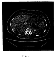
- a 2-D slice image of the sort generated by scanning device 5 and displayed on display 20 might comprise the 2-D slice image shown in Fig. 2.
- the 2-D slice image shown corresponds to an axial slice taken through an individual's abdomen and showing, among other things, that individual's liver.
- Scanning device 5 may format its scanning data in any one of a number of different data structures.
- scanning device 5 might format its scanning data in the particular data format used by a CT scanner of the sort manufactured by GE Medical Systems of Milwaukee, Wisconsin. More specifically, with such a scanning device, the scanning data is generally held as a series of data "frames", where each data frame corresponds to a particular 2-D slice image taken through the patient's body. Furthermore, within each data frame, the scanning data is generally organized so as to represent the scanned anatomical structure at a particular location within that 2-D slice image.
- Such a data structure is fairly common for scanning devices of the sort associated with the present invention. However, it should be appreciated that the present invention is not dependent on the particular data format utilized by scanning device 5.
- the scanning data provided by scanning device 5 can be formatted in almost any desired data structure, so long as that data structure is well defined, whereby the scanning data can be retrieved and utilized as will hereinafter be disclosed in further detail.
- a series of data frames 30A, 30B, 30C, etc. are shown arranged in a parallel array.
- Each of these data frames 30A, 30B, 30C, etc. corresponds to a particular 2-D slice image taken through the patient's body by scanning device 5, where the 2-D slice images are taken parallel to one another.
- adjacent image planes or slices are spaced apart by a constant, pre-determined distance, e.g., 1 mm.
- data frames 30A, 30B, 30C, etc. collectively form a volumetric data set which is representative of the patient's scanned anatomical structure.
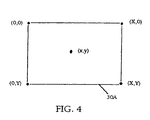
- the scanning data contained within an exemplary data frame 30A is shown represented in an X-Y coordinate scheme so as to quickly and easily identify the scanned anatomical structure disposed at a particular location within that 2-D slice image.
- the scanning data relating to a particular X-Y coordinate represents an image intensity value. This image intensity value generally reflects some attribute of the specific anatomical structure being scanned, e.g., the tissue density.
- the scanning data generated by scanning device 5 is stored in its 2-D slice image data form in first section 23 of data storage device or medium 25, with the scanning data being stored in a particular data format as determined by the manufacturer of scanning device 5.
- the scanning data stored in first section 23 of data storage device or medium 25 is retrieved, processed and then stored again in a data storage device or medium 30.
- the scanning data stored in first section 23 of data storage device or medium 25 is retrieved and processed so as to convert the scanning data generated by scanning device 5 from its 2-D slice image data form into a 3-D computer model of the patient's anatomical structure.
- This 3-D computer model is then stored in a first section 35 of data storage device or medium 30.
- the scanning data stored in first section 23 of data storage device or medium 25 is retrieved and processed as necessary so as to convert the scanning data into a preferred data format for the 2-D slice image data.
- the 2-D slice image data is then stored in this preferred data format in second section 40 of data storage device or medium 30.
- the additional information associated with the scanning data (e.g., patient name, age, etc.) which was previously stored in second section 27 of data storage device or medium 25 can be stored in a third section 42 of data storage device or medium 30.
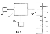
- the 3-D computer model has been stored in first section 35 of data storage device or medium 30, and the 2-D slice image data has been stored in a preferred data format in second section 40 of data storage device or medium 30, a physician can then use an appropriately programmed computer to access the 3-D computer model stored in first section 35 of data storage device or medium 30, and/or the 2-D slice image data stored in second section 40 of data storage device or medium 30, to generate desired patient-specific images.
- a physician can use an appropriately programmed computer 50, operated by input devices 55, to access the 3-D computer model stored in first section 35 of data storage device or medium 30, and/or the 2-D slice image data stored in second section 40 of data storage device or medium 30, so as to generate the desired patient-specific images and display those images on a display 60.
- the 3-D computer model contained in first section 35 of data storage device or medium 30 is preferably structured as a collection of software objects, with each software object being defined by a polygonal surface model of the sort well known in the art.
- a scanned anatomical structure such as a human liver might be modeled as three distinct software objects, with the outer surface of the general mass of the liver being one software object, the outer surface of the vascular structure of the liver being a second software object, and the outer surface of a tumor located in the liver being a third software object.
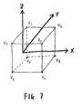
- Figs. 7 and 8 illustrate a typical manner of defining a software object by a polygonal surface model.
- Fig. 7 and 8 illustrate a typical manner of defining a software object by a polygonal surface model.
- FIG. 7 illustrates the vertices of a unit cube set in an X-Y-Z coordinate system
- Fig. 8 illustrates the data file format of the polygonal surface model for this simple unit cube.
- more complex shapes such as human anatomical structure can be expressed in corresponding terms.
- first section 35 of data storage device or medium 30 is created by analyzing the 2-D slice image data stored in first section 23 of data storage device or medium 25 using techniques well known in the art.
- the 2-D slice image data stored in first section 23 of data storage device or medium 25 might be processed using the well known "Marching Cubes” algorithm, which is a so-called “brute force” surface construction algorithm that extracts isodensity surfaces from a volumetric data set, producing from one to five triangles within voxels that contain the surface.
- the 2-D slice image data stored in first section 23 of data storage device or medium 25 might be processed into the 3-D computer model stored in first section 35 of data storage device or medium 30 by some other appropriate modeling algorithm so as to yield the desired 3-D computer model which is stored in first section 35 of data storage device or medium 30.
- the specific data structure used to store the 2-D slice image data in second section 40 of data storage device or medium 30 will also depend on the specific nature of computer 50 and on the particular operating system and application software being run on computer 50.
- the 2-D slice image data contained in second section 40 of data storage device or medium 30 is preferably structured as a series of data "frames", where each data frame corresponds to a particular 2-D slice image taken through the patient's body, and where the scanning data within each data frame is organized so as to represent the scanned anatomical structure at a particular location within that 2-D slice image.
- computer 50 comprise a Power PC-based, Macintosh operating system ("Mac OS") type of computer, e.g. a Power PC Macintosh 8100/80 of the sort manufactured by Apple Computer, Inc. of Cupertino, California.
- Mac OS Power PC-based, Macintosh operating system
- computer 50 be running Macintosh operating system software, e.g. Mac OS Ver. 7.5.1, such that computer 50 can readily access a 3-D computer model formatted in Apple's well-known QuickDraw 3D data format and display images generated from that 3D computer model, and such that computer 50 can readily access and display 2-D images formatted in Apple's well-known QuickTime image data format.
- Input devices 55 preferably comprise the usual computer input devices associated with a Power PC-based, Macintosh operating system computer, e.g., input devices 55 preferably comprise a keyboard, a mouse, etc.
- the 3-D computer model contained in first section 35 of data storage device or medium 30 be formatted in Apple's QuickDraw 3D data format, whereby the Mac OS computer 50 can quickly and easily access the 3-D computer model contained in first section 35 of data storage device or medium 30 and display images generated from that 3-D computer model on display 60.
- the 2-D slice image data contained in second section 40 of data storage device or medium 30 be formatted in Apple's QuickTime image data format.
- computer 50 can quickly and easily display the scanned 2-D slice images obtained by scanning device 5.
- scanning device 5 happens to format its scanning data in the preferred QuickTime image data format
- no reformatting of the 2-D slice image data will be necessary prior to storing the 2-D slice image data in second section 40 of data storage device or medium 30.
- reformatting of the 2-D slice image data will be necessary so as to put it into the preferred QuickTime image data format.
- Such image data reformatting is of the sort well known in the art.
- a physician operating computer 50 through input devices 55 can generate a desired image from the 3-D computer model contained within first section 35 of data storage device or medium 30.
- the physician can use input devices 55 to (1) open a window on display 60, (2) instruct the computer as to the desired angle of view, (3) generate the corresponding image of the scanned anatomical structure from the desired angle of view, using the 3-D computer model contained within first section 35 of data storage device or medium 30, and (4) display that image in the open window on display 60.
- a physician operating computer 50 through input devices 55 can display a desired 2-D slice image from the 2-D slice image data contained within second section 40 of data storage device or medium 30.
- the physician can use input devices 55 to (1) open a window on display 60, (2) select a particular 2-D slice image contained within second section 40 of data storage device or medium 30, and (3) display that slice image in the open window on display 60.
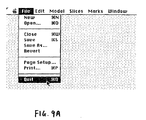
- computer 50 is preferably programmed so as to provide a variety of pre-determined menu choices which may be selected by the physician operating computer 50 via input devices 55.
- Fig. 10 illustrates an image drawn to a window using the data contained in the 3-D computer model stored in first section 35 of data storage device or medium 30.
- the physician can use input devices 55 to instruct the image rendering software as to the specific angle of view desired.
- computer 50 is preferably programmed so that the physician can depress a mouse key and then drag on the object so as to rotate the object into the desired angle of view. Additionally, computer 50 is preferably programmed so that the physician can also use the keyboard and mouse to move the view closer in or further out, or to translate the object side to side or up and down relative to the image plane. Programming to effect such computer operation is of the sort well known in the art.
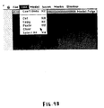
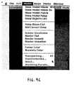
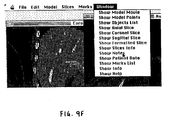
- Figs. 9A-9F the physician can use menu choices such as those shown in Figs. 9A-9F to open a window on the display 60 and then to display in that window a desired 2-D slice image from second section 40 of data storage device or medium 30.
- Computer 50 is programmed so that the physician can select between different slice images by means of input devices 55.
- Fig. 11 illustrates a 2-D slice image drawn to a window by the operating system using the data contained in second section 40 of data storage device or medium 30.
- computer 50 is programmed so that, by dragging icon 70 back and forth along slider 75, the physician can "leaf" back and forth through the collection of axial slices, i.e., in the example of Fig.
- computer 50 is preferably programmed so that the physician can also step the image from the current slice number to a previous or following slice number by using menu commands or by clicking the mouse cursor on the single step icons 76 set at the right side of slider 75.
- Computer 50 is preferably also programmed so that menu commands are provided to change the slice window display directly to the first or last slice image in the 2-D slice image set, or to change the slice window display to a user-specified slice number. Programming to effect such computer operation is of the sort well known in the art.
- the aforementioned hardware and software architecture i.e., the Macintosh computer, the Mac OS, the Apple QuickDraw 3D data format and software, and the Apple QuickTime image data format and software, or some equivalent hardware and software
- an additional software object into the 3-D computer model contained within first section 35 of data storage device or medium 30.
- the computer's image rendering software it is possible to texture map a 2-D slice image from second section 40 of data storage device or medium 30 onto the blank planar surface of the inserted software object.
- both 3-D model structure and 2-D slice image structure can be simultaneously displayed in proper registration with one another, thereby providing a single composite image of the two separate images. See, for example, Fig. 12, which shows such a composite image.
- computer 50 is programmed so that the physician can use input devices 55 to instruct the operating system's image rendering software as to where the aforementioned "additional" software object is to be inserted into the model and as to the particular angle of view desired. Programming to effect such computer operation is of the sort well known in the art.
- computer 50 is also programmed so that (1) the physician can use input devices 55 to select a particular 2-D slice image from the second section 40 of data storage device or medium 30, and (2) the computer will then automatically insert the aforementioned additional software object into the 3-D computer model so that the object's "blank" planar surface is located at the position which corresponds to the position of the selected 2-D slice image relative to the scanned anatomical structure.
- programming to effect such computer operation is of the sort well known in the art.
- the 2-D slice image data generated by scanning device 5 has generally been discussed in the context of the standard "axial" slice images normally generated by scanning devices of the type associated with this invention.
- the present invention is also adapted to utilize sagittal and/or coronal 2-D slice images.
- the present invention is adapted to utilize oblique slice images of the type hereinafter described.
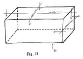
- Fig. 13 the relative orientation of axial, sagittal and coronal slice images are shown in the context of a schematic view of a human body 80.
- Scanning device 5 will normally generate axial slice image data when scanning a patent.
- scanning device 5 will also assemble the axial slice data into a 3-D database (i.e., a volumetric data set) of the scanned anatomical structure, and then use this 3-D database to generate a corresponding set of sagittal and/or coronal 2-D slice images.
- a 3-D database i.e., a volumetric data set
- scanning device 5 does not have the capability of generating the aforementioned sagittal and/or coronal 2-D slice images
- sagittal and/or coronal 2-D slice images may be generated from a set of the axial 2-D images in a subsequent operation, using computer hardware and software of the sort well known in the art.
- computer 50 may be programmed to render such sagittal and/or coronal 2-D slices "on the fly" from the 2-D slice image data contained in second section 40 of data storage device or medium 30.
- the sagittal and coronal 2-D slice image data may be stored with the axial slice image data in second section 40 of data storage device or medium 30.
- these sagittal and coronal slice images are stored in exactly the same data format as the 2-D axial slice images, whereby they may be easily accessed by computer 50 and displayed on display 60 in the same manner as has been previously discussed in connection with axial 2-D slice images.
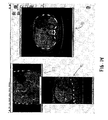
- axial, sagittal and coronal 2-D slice images can be displayed on display 60, either individually or simultaneously in separate windows, in the manner shown in Fig. 14.
- the composite image can be created using axial, sagittal or coronal 2-D slice images, as preferred.
- system of the present invention is also configured so as to generate and utilize oblique 2-D slice image data in place of the axial, sagittal and coronal slice image data described above.
- computer 50 is programmed so that a physician can use input devices 55 to specify the location of the oblique 2-D slice image desired, and then computer 50 generates that 2-D slice image from the volumetric data set present in second section 40 of data storage device or medium 30 (i.e., from the collection of 2-D slice images contained in second section 40 of data storage device or medium 30).
- data storage device or medium 30 can comprise conventional storage media (e.g., a hard disk, a CD ROM, a tape cartridge, etc.), which can be located either onsite or at a remote location linked via appropriate data transfer means.
- conventional storage media e.g., a hard disk, a CD ROM, a tape cartridge, etc.
- computer 50 is programmed so that a physician can display a specific 2-D slice image in a window opened on display 60, place a marker into that specific 2-D slice image using a mouse or other input device 55, and then have that marker automatically incorporated into both (i) the 3-D computer model contained in first section 35 of data storage device or medium 30, and (ii) any appropriate 2-D slice image data contained in second section 40 of data storage device or medium 30.
- a physician can display a specific 2-D slice image in a window opened on display 60, place a marker into that specific 2-D slice image using a mouse or other input device 55, and then have that marker automatically incorporated into both (i) the 3-D computer model contained in first section 35 of data storage device or medium 30, and (ii) any appropriate 2-D slice image data contained in second section 40 of data storage device or medium 30.
- images are thereafter generated from the 3-D computer model contained in first section 35 of data storage device or medium 30, and/or from the 2-D slice image data contained in second section 40 of data storage device or medium 30, these subsequent images will automatically
- marker 85 displayed in its appropriate location in each of the three displayed 2-D slice images, i.e., in axial slice image 90, sagittal slice image 95, and coronal slice image 100. It is to be appreciated that it is also possible for marker 85 to be displayed where appropriate in an image generated from the 3-D computer model contained in first section 35 of data storage device or medium 30; see, for example, Fig. 15, which shows such a marker 85 being displayed in the image.
- computer 50 is programmed so that a physician can generate a "margin" of some predetermined size around such a marker.
- a margin 105 has been placed around marker 85.
- margin 105 will appear as a 3-dimensional spherical shape around marker 85, just as marker 85 appears as a 3-dimensional shape, since the view of Fig. 15 is generated from the 3-D computer model contained in first section 35 of data storage device or medium 30.
- marker 85 and margin 105 are displayed in the context of 2-D slice images, the marker and margin will appear as simple circles.
- Margin 105 can be used by a physician to determine certain spatial relationships in the context of the anatomical structure being displayed on the computer.
- first section 35 of data storage device or medium 30 constitutes a plurality of software objects defined by polygonal surface models
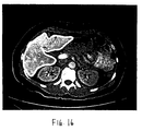
- computer 50 is programmed so that a physician can select one or more anatomical structures using an input device 55, and the computer will then highlight the periphery of that structure in any corresponding 2-D slice images displayed on display 60. See, for example, Fig. 16, where a boundary 110 is shown outlining the periphery of an object 115 displayed in a 2-D slice image.
- the present invention has been described in the context of an anatomical visualization system being used by a physician, it is also to be appreciated that the system could be used in conjunction with inanimate objects being viewed by a non-physician, e.g., the system could be used to visualize substantially any object for which a 3-D computer model and a collection of 2-D slice image data can be assembled.
- surface model is intended to include polygonal surface models, parametric surface models such as B-spline surface models, quadralateral meshes, etc.
- the visualization and measurement system may incorporate means for determining patient-specific anatomical dimensions using appropriate scanned 2-D image data.
- this aspect of the present invention will be discussed in the context of measuring a patient's vascular structure in the region of the aortic/iliac branching.
- such measurement might be conducted in the course of repairing an aortic aneurysm through installation of a vascular prosthesis.
- a set of 2-D slice images is first generated, where each 2-D slice image corresponds to a specific viewing plane or "slice" taken through the patient's body.
- different types of tissue are typically represented by different image intensities.
- Fig. 17 illustrates a 2-D slice image 200 taken through the abdomen of a patient, at a location above the aortic/iliac branching
- Fig. 18 illustrates a 2-D slice image 202 taken through the abdomen of the same patient, at a location below the aortic/iliac branching.
- vascular tissue might be shown at 205, bone at 207, other tissue at 210, etc. An appropriate set of these 2-D.
- slice images is assembled into a 3-D database so as to provide a volumetric data set corresponding to the anatomical structure of the patient.
- the set of 2-D slice images making up this 3-D database might be stored in second section 40 of data storage device or medium 30.
- the 3-D database being referred to now is not the same as the 3-D computer model contained in first section 35 of data storage device or medium 30; rather, the 3-D database being referred to now is simply a volumetric data set made up of the series of 2-D slice images contained in second section 40 of data storage device or medium 30.
- the patient-specific volumetric data set (formed out of the collection of 2-D slice images contained in the 3-D database) is segmented so as to highlight the anatomical structure of interest.
- each of these 2-D images corresponds to a specific viewing plane or "slice" taken through the patient's body; or, stated slightly differently, each of these 2-D images essentially represents a plane cutting through the patient-specific volumetric data set contained in the 3-D database.
- the different types of tissue will generally be represented by different image intensities.
- the user (who might or might not be a physician) selects a particular 2-D slice image for viewing on display 60, e.g., "slice image #155".
- the user uses one or more of the input devices 55 to select one or more points located within the anatomical structure of interest.
- such user-selected points can be referred to as "seeds”. See, for example, Fig. 17, where a seed point 215 has been selected within the interior of vascular tissue 205 so as to identify blood.
- the user also uses one or more of the input devices 55 to specify a range of image intensities that appear to correspond to the anatomical structure of interest in the volumetric data set, e.g., blood within the interior of a blood vessel.
- the appropriately programmed computer 50 then applies a segmentation algorithm of the sort well known in the art to segment out related structure within the patient-specific 3-D database.
- computer 50 is programmed to apply a 3-D connected component search through the volumetric data set contained in second section 40 of data storage device or medium 30 so as to determine the set of volumetric samples that are (i) within the range specified for blood, and which (ii) can be connected along a connected path back to one of the seeds, where each of the locations along the path is also within the range specified for blood.
- the result of this 3-D connected component search is a set of 3-D locations in the volumetric data set which correspond to blood flowing through the blood vessel.
- this set of 3-D locations can be characterized as the "blood region".
- the segmented anatomical structure i.e., the blood in the blood region
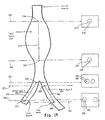
- the branches in the segmented anatomical structure are identified. For example, and looking now at Fig. 19, in the present illustration dealing with vascular structure in the region of the aortic/iliac branching, the aorta and the two iliac branches would be separately identified.
- the user specifies a branch line in the volumetric data set that uniquely indicates that vessel segment. This is accomplished by using one or more of the input devices 55 to select, for each branch line, an appropriate "start” location on one of the 2-D slice images contained within second section 40 of data storage device or medium 30, and an appropriate "end” location on another one of the 2-D slice images contained within second section 40 of data storage device or medium 30.
- branch lines do not need to cover the entire length of interest of the vessel and, in practice, will tend to stop somewhat short of the junction where various branches converge with one another. At the same time, however, for improved accuracy of modeling the branching structure, the branch lines should extend close to the bifurcation point.
- the start and end locations are used to subdivide the blood region as follows: the region for that vessel branch is the set of locations within the blood region that are between the start plane and the end plane, where the start plane for each vessel branch is the 2-D image plane passing through the start location for the corresponding branch line, and the end plane for each vessel branch is the 2-D image plane passing through the end location for each vessel branch.
- a vessel branch structure consisting of just three vessel segments coming together at a branch point, e.g., a vessel branch structure such as the aortic/iliac branching shown in Fig. 19.
- the user would designate one vessel region as the root region (e.g., the aortic region 220 defined by a branch line 225 having a start location 230 contained in a start plane 235, and an end location 240 contained in an end plane 245) and the other vessel regions as branch region A (e.g., the iliac region 250 defined by a branch line 255 having a start location 260 contained in a start plane 265, and an end location 270 contained in an end plane 275), and branch region B (e.g., the iliac region 280 defined by a branch line 285 having a start location 290 contained in a start plane 295, and an end location 300 contained in an end plane 305), respectively.
- branch region A e.g., the iliac region 250 defined by a branch line 255 having a start location 260 contained in a start plane 265, and an end location 270 contained in an end plane 275
- branch region B e.g., the iliac region 280 defined by a branch line
- a centroid path is then calculated. This is accomplished in the following manner. First, at intervals along the vessel line corresponding to the volumetric location of each of the original 2-D slice images contained in second section 40 of data storage device or medium 30, the centroid of the vessel region in that particular 2-D slice image is calculated. This is done by averaging the image coordinates of all locations in that 2-D slice image that are within the vessel region so as to yield a centroid point. See, for example, Fig. 20, which schematically illustrates the manner of calculating the centroid 310 for a representative vessel region 312 in a representative 2-D slice image 315.
- centroid path for each vessel region is then established by the collective set of centroid points located along that vessel segment in three-dimensional space.
- the tortuous path corresponding to the root region is called the root centroid path and the tortuous paths corresponding to branch regions A and B are called branch centroid path A and branch centroid path B, respectively.
- Fig. 21 shows a plurality of centroids 320, a root centroid path generally indicated at 325, a branch centroid path A generally indicated at 330, and a branch centroid path B generally indicated at 335, all shown in the context of a vessel branch structure such as the aortic/iliac branching example discussed above. It is to be appreciated that no centroids will be defined in the "unknown" region 336 bounded by the end plane 245 and the start plane 265, and the "unknown" region 337 bounded by the end plane 245 and the start plane 295.
- the system is programmed so that it will then apply a curve-fitting algorithm to the tortuous centroid paths determined above so as to supply estimated data for any portions of the anatomical structure which may lie between the aforementioned branch lines, and for "smoothing out” any noise that may occur in the system.
- a spline fitting algorithm effected in the following manner.
- two new paths are created, by concatenating the points in the root centroid path 325 with the points in each of the two branch centroid paths 330 and 335, so as to create a path root-A and a path root-B.
- These two new paths are then used as the input to a spline fitting routine which selects the coefficients for a piecewise polynomial space curve that best approximates the points along the path in a least-squares sense.
- the number of pieces of the approximation and the order of polynomial may be varied by the user.
- the resulting curves may be called spline-root-A and spline-root-B. See, for example, Fig. 22, which illustrates the spline-root-B, generally indicated at 340.
- the distance along the two splines i.e., spline-root-A and spline-root-B
- the result can be presented to the user.
- These calculations can be used for a variety of purposes, e.g., to help determine the appropriate size of a vascular prosthesis to be used in repairing an aneurysm at the aortic/iliac junction.
- a tangent vector and a perpendicular plane can be readily determined either by direct calculation or by definition in those cases where direct calculation would be undefined.
- the shape of the vessel at that point can be determined, and the radius of a circle that best fits the cross-sectional area of the vessel at that point can also be readily calculated. Again, this result can be used to help determine that desired graft shape.
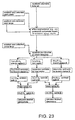
- Fig. 23 is a flow chart illustrating how patient-specific anatomical dimensions can be determined from scanned 2-D data in accordance with the present invention.
- the centerline derived above it is possible to use the centerline derived above to construct a series of oblique slices through the volumetric data set (which volumetric data set is formed out of the assembled scanned 2-D slice images contained in second section 40 of data storage device or medium 30) such that the reconstructed oblique slices are disposed perpendicular to the centerline.
- oblique slices per se are generally well known in the art, to the extent that such oblique slices are arbitrary planar resamplings of the volumetric data set.
- the utility of these arbitrary oblique slices is limited for many applications, since there is no explicit, well-defined relationship between their position and anatomical structures of interest.
- oblique slices taken perpendicular to the length of the blood vessel are of particular importance to the physician.
- This problem is avoided with the present invention, which utilizes the centerline as derived above to generate the set of oblique slices lying perpendicular to the blood vessel.
- This set of oblique slices derived from the centerline is preferably stored in a fourth section 400 of data storage device or medium 30 (Figs. 5 and 6).
- any oblique slice In general, one way to think about generating any oblique slice is to consider a four-sided polygon that is placed in the space defined by the volumetric data set. This polygon is then scan converted to resample the axial images so as to generate the oblique slice desired.
- scan converted is intended to refer to the well-known techniques of subdividing a polygon into regularly spaced intervals on a rectangular grid.
- a programmable computer is used to generate the specific set of oblique slices that is defined by the centerline derived above. This is accomplished as follows. First, the centerline is divided into n increments. This can be done with points P 0 , P 1 , ..., P n , as shown in Fig. 24. A line T i is then derived for each of the points P i , where T i is the tangent line at that point P i . Finally a series of oblique slices are produced by constructing a series of four-sided polygons, each of which is centered at P i and normal to T i .
- the locations of the corners of the polygon are selected such that the resulting image orientation is as close as possible to a preselected image orientation (e.g., axial).
- These four-sided polygons are then scan converted as described above so as to provide the set of oblique slice images lying perpendicular to the centerline.
- this set of oblique slice images is stored in fourth section 400 of data storage device or medium 30.
- the corner locations of each four-sided polygon associated with each oblique slice image is also stored in fourth section 400 of data storage device or medium 30, whereby the precise location of each oblique slice image within the volumetric data set is established.
- the oblique slice images stored in fourth section 400 of data storage device or medium 30 is available to be accessed by computer 50 in exactly the same manner as the 2-D axial slice images stored in second section 40 of data storage device or medium 30.
- these oblique slices can then be used for a variety of additional purposes.
- the oblique slice images derived from the centerline can be accessed by computer 50 from fourth section 400 of data storage device or medium 30.
- the physician can then use input devices 55 to instruct computer 50 to access the oblique slice at a particular location along the blood vessel and measure the diameter of the same.
- the physician can use input devices 55 to access the particular oblique slice desired and then lay down two diametrically-opposed marks so as to define the diameter of the blood vessel; the computer is adapted in ways well known in the art to then calculate the distance between the two marks.
- the cumulative sum table can be of the sort shown in Fig. 25.
- This cumulative sum table is preferably stored in a fifth section 405 of data storage device or medium 30.
- Computer 50 is also programmed so that the user interface presents a centerline length calculation dialogue box 407 (Fig. 26) to the physician on display 60, by which the physician can specify (using input devices 55) two oblique slice images which are the end points of the length which is to be determined.
- Computer 50 is programmed so that it will then determine the length between the two chosen oblique slices by calculating the difference in their positions from the cumulative sum table.
- Computer 50 is also programmed so that a 3-D graphical icon 408 (Fig. 27) is inserted into the 3-D model contained in first section 35 of data storage device or medium 30.
- This icon represents the portion of the vessel centerline which has been specified by the physician via the two oblique slice images which represent the length end points.
- a cumulative sum table can also be used to calculate volumes with respect to an anatomical structure, in much the same way that a cumulative sum table can be used to calculate lengths along an anatomical structure.
- incremental slice volumes are more appropriately calculated in the axial direction rather than in the oblique slice direction. This is because the axial slices all lie parallel to one another, whereas the oblique slices (since they are generated from the centerline) do not.
- a computer is used to calculate the volume of each axial slice, V i , by (1) determining the number of pixels in the segmented region of that axial slice, (2) scaling by the appropriate pixel-to-length factor, and then (3) multiplying by the slice thickness.
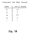
- this cumulative sum table can be of the sort shown in Fig. 28.
- This cumulative sum table is stored in sixth section 410 of data storage device or medium 30.
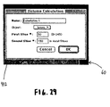
- Computer 50 is also programmed so that the user interface presents a volume calculation dialogue box 412 (Fig.
- Computer 50 calculates the volume for the region specified, using the cumulative sum table.
- Computer 50 is also programmed so as to place a 3-D graphical icon 415 (Fig. 30) in the 3-D model contained in the first section 35 of data storage device or medium 30. This icon represents the volume specified by the physician using the volume calculation dialogue box.
Landscapes
- Physics & Mathematics (AREA)
- Engineering & Computer Science (AREA)
- Geometry (AREA)
- Computer Vision & Pattern Recognition (AREA)
- General Physics & Mathematics (AREA)
- Theoretical Computer Science (AREA)
- Measuring And Recording Apparatus For Diagnosis (AREA)
- Apparatus For Radiation Diagnosis (AREA)
Claims (11)
- System zur Bestimmung einer Dimension einer anatomischen Struktur unter Benutzung eines geeigneten Sets von 2-D Scheibenbildern erhalten durch das Scannen der anatomischen Struktur bestehend aus:Mitteln zur Zusammensetzung des Sets der gescannten 2-D Scheibenbilder in eine 3-D Datenbank;Mitteln zur Gewinnung eines anatomischen Merkmals durch die in der 3-D Datenbank enthaltenen Informationen;Mitteln zur Spezifizierung einer Messung die basierend auf dem gewonnenen anatomischen Merkmal gemacht wird, dieses anatomische Merkmal ist die Mittellinie der anatomischen Struktur;
undMitteln zur Kalkulation der so spezifizierten Messung;charakteristisch enthält das System eine anwachsende Summentabelle hergeleitet aus dieser Mittellinie, wobei diese anwachsende Summentabelle inkrementale Abstände zwischen Punkten auf vorgenannter Mittellinie speichert und weiterhin die besagten Mittel zur Kalkulation vorgenannte anwachsende Summentabelle zur Bestimmung einer Längenabmessung verwerten, wobei diese Mittellinie von einem Pfad aus Schwerpunkten hergeleitet ist, welcher bestimmt ist von einer Durchschnittsbildung der Schwerpunkte dieses Sets von 2-D Scheibenbildern der danach durch einen Kurvenalgorithmus geglättet wurde. - Ein System gemäß Anspruch 1, weiter enthaltend Mittel zur Erzeugung eines Sets von schrägen Scheibenbildern aus der 3-D Datenbank, wobei die Orientierung dieser schrägen Scheibenbilder durch die Konfiguration des anatomischen Merkmals bestimmt wird.
- Ein System gemäß Anspruch 2, wobei dieses System Mittel zur Spezifizierung einer Messung enthält, welche basierend auf einem dieser schrägen Scheibenbilder gemacht wird.
- System zur Bestimmung einer Dimension einer anatomischen Struktur unter Benutzung eines geeigneten Sets von 2-D Scheibenbildern erhalten durch das Scannen der anatomischen Struktur bestehend aus:Mitteln zur Zusammensetzung des Sets der gescannten 2-D Scheibenbilder in eine 3-D Datenbank;Mitteln zur Gewinnung eines anatomischen Merkmals durch die in der 3-D Datenbank enthaltenen Informationen;Mitteln zur Spezifizierung einer Messung die basierend auf dem gewonnenen anatomischen Merkmal gemacht wird,
undMitteln zur Kalkulation einer Messung, wie folgt spezifiziert;charakteristisch enthält das System eine anwachsende Summentabelle hergeleitet von diesem anatomischen Merkmal, wobei diese anwachsende Summentabelle inkrementale Volumina dieses anatomischen Merkmals speichert und dieses Volumen hergeleitet ist aus der Bildinformation der 2-D Scheibenbilder und deren Entfernungen davon und weiterhin wobei dies Mittel zur Kalkulation vorgenannte anwachsende Summentabelle zur Bestimmung einer Volumenmessung verwertet. - Ein System nach einem der Ansprüche 1-4, gekennzeichnet durch Mittel zur Visualisierung einer anatomischen Struktur durch Mittel zur Spezifizierung einer Ansicht, wiedergegeben auf Basis dieses extrahierten anatomischen Merkmals und Mittel zur Wiedergabe der so spezifizierten Ansicht.
- Ein System nach Anspruch 5 weiterhin enthaltend Mittel zur Generierung eines Sets von schrägen Scheibenbildern aus vorgenannter 3-D Datenbank, wobei die Orientierung dieser schrägen Scheibenbilder durch die Konfiguration des anatomischen Merkmals bestimmt wird.
- Ein System nach Anspruch 4, wobei dieses anatomische Merkmal die Mittellinie dieser anatomischen Struktur ist.
- verfahren zur Bestimmung einer Dimension einer anatomischen Struktur unter Benutzung eines geeigneten Sets von 2-D Scheibenbildnern, erhalten durch das Scannen der anatomischen Struktur, folgende Schritte beinhaltend:(1) Zusammensetzung dieses Sets von gescannten 2-D Scheibenbildern in eine 3-D Datenbank(2) Gewinnung eines anatomischen Merkmals durch die aus der 3-D Datenbank erhaltenen Informationen(3) Spezifizierung einer Messung, die basierend auf dem hergeleiteten anatomischen Merkmal gemacht wird; und(4) Kalkulation einer Messung, wie folgt spezifiziert;
dieses anatomische Merkmal ist die Mittellinie der besagten anatomischen Struktur; diese Mittellinie ist von einem Pfad aus Schwerpunkten hergeleitet, welcher bestimmt ist von einer Durchschnittsbildung der Schwerpunkte dieses Sets von 2-D Scheibenbildern der danach durch einen Kurvenalgorithmus geglättet wurde,
und
wobei Schritt (2) den Schritt zur Erzeugung einer anwachsenden Summentabelle aus dieser besagten Mittellinie beinhaltet, wobei diese anwachsende Summentabelle die anwachsenden Entfernungen zwischen Punkten auf dieser Mittellinie speichert und wobei weiterhin Schritte (3) und (4) im Hinblick auf diese anwachsende Summentabelle geführt sind, um eine Längenmessung zu bestimmen. - Verfahren nach Anspruch 8, gekennzeichnet durch den Schritt der Visualisierung einer anatomischen Struktur durch Spezifizierung einer Ansicht, basierend auf diesem extrahierten anatomisch wiedergegeben Merkmal und Wiedergabe einer so spezifizierten Ansicht.
- Verfahren nach Anspruch 9, einschließlich der Erzeugung eines Sets von schrägen Scheibenbildern aus dieser 3-D Datenbank, wobei die Orientierung dieser schrägen Scheibenbilder durch die Konfiguration des anatomischen Merkmals bestimmt wird.
- Verfahren nach Anspruch 9, wobei dieses anatomische Merkmal die Mittellinie dieser anatomischen Struktur ist.
Applications Claiming Priority (3)
| Application Number | Priority Date | Filing Date | Title |
|---|---|---|---|
| US581055 | 1995-12-29 | ||
| US08/581,055 US5825908A (en) | 1995-12-29 | 1995-12-29 | Anatomical visualization and measurement system |
| PCT/US1996/020841 WO1997024697A1 (en) | 1995-12-29 | 1996-12-26 | Anatomical visualization and measurement system |
Publications (3)
| Publication Number | Publication Date |
|---|---|
| EP0954830A1 EP0954830A1 (de) | 1999-11-10 |
| EP0954830A4 EP0954830A4 (de) | 2001-06-06 |
| EP0954830B1 true EP0954830B1 (de) | 2006-03-08 |
Family
ID=24323720
Family Applications (1)
| Application Number | Title | Priority Date | Filing Date |
|---|---|---|---|
| EP96945436A Expired - Lifetime EP0954830B1 (de) | 1995-12-29 | 1996-12-26 | Anatomisches visualisierungs- und messsystem |
Country Status (5)
| Country | Link |
|---|---|
| US (3) | US5825908A (de) |
| EP (1) | EP0954830B1 (de) |
| AU (1) | AU1568897A (de) |
| DE (1) | DE69635906T2 (de) |
| WO (1) | WO1997024697A1 (de) |
Cited By (3)
| Publication number | Priority date | Publication date | Assignee | Title |
|---|---|---|---|---|
| US9047685B2 (en) | 2007-05-30 | 2015-06-02 | The Cleveland Clinic Foundation | Automated centerline extraction method and generation of corresponding analytical expression and use thereof |
| US11132801B2 (en) | 2018-02-02 | 2021-09-28 | Centerline Biomedical, Inc. | Segmentation of three-dimensional images containing anatomic structures |
| US11380043B2 (en) | 2019-04-04 | 2022-07-05 | Centerline Biomedical, Inc. | Modeling regions of interest of an anatomic structure |
Families Citing this family (113)
| Publication number | Priority date | Publication date | Assignee | Title |
|---|---|---|---|---|
| US5782762A (en) | 1994-10-27 | 1998-07-21 | Wake Forest University | Method and system for producing interactive, three-dimensional renderings of selected body organs having hollow lumens to enable simulated movement through the lumen |
| US5825908A (en) * | 1995-12-29 | 1998-10-20 | Medical Media Systems | Anatomical visualization and measurement system |
| US5986662A (en) * | 1996-10-16 | 1999-11-16 | Vital Images, Inc. | Advanced diagnostic viewer employing automated protocol selection for volume-rendered imaging |
| US8682045B2 (en) | 1997-02-25 | 2014-03-25 | Wake Forest University Health Sciences | Virtual endoscopy with improved image segmentation and lesion detection |
| US6165193A (en) * | 1998-07-06 | 2000-12-26 | Microvention, Inc. | Vascular embolization with an expansible implant |
| FR2781140B1 (fr) * | 1998-07-17 | 2000-11-10 | Ge Medical Syst Sa | Procede de positionnement d'un appareil de radiologie |
| US6033415A (en) * | 1998-09-14 | 2000-03-07 | Integrated Surgical Systems | System and method for performing image directed robotic orthopaedic procedures without a fiducial reference system |
| US8600551B2 (en) * | 1998-11-20 | 2013-12-03 | Intuitive Surgical Operations, Inc. | Medical robotic system with operatively couplable simulator unit for surgeon training |
| US6852107B2 (en) | 2002-01-16 | 2005-02-08 | Computer Motion, Inc. | Minimally invasive surgical training using robotics and tele-collaboration |
| US8527094B2 (en) | 1998-11-20 | 2013-09-03 | Intuitive Surgical Operations, Inc. | Multi-user medical robotic system for collaboration or training in minimally invasive surgical procedures |
| US6398726B1 (en) | 1998-11-20 | 2002-06-04 | Intuitive Surgical, Inc. | Stabilizer for robotic beating-heart surgery |
| US6659939B2 (en) | 1998-11-20 | 2003-12-09 | Intuitive Surgical, Inc. | Cooperative minimally invasive telesurgical system |
| EP2302596A1 (de) | 1998-11-25 | 2011-03-30 | Wake Forest University | Virtuelle Endoskopie mit verbesserter Bildsegmentierung und Läsionsdetektion |
| JP4342016B2 (ja) * | 1999-01-06 | 2009-10-14 | 株式会社日立メディコ | 画像表示装置 |
| US6556695B1 (en) | 1999-02-05 | 2003-04-29 | Mayo Foundation For Medical Education And Research | Method for producing high resolution real-time images, of structure and function during medical procedures |
| US7068825B2 (en) * | 1999-03-08 | 2006-06-27 | Orametrix, Inc. | Scanning system and calibration method for capturing precise three-dimensional information of objects |
| US6278767B1 (en) * | 1999-04-28 | 2001-08-21 | General Electric Company | Methods for measuring curved distances on 3D and MIP images |
| US6785410B2 (en) * | 1999-08-09 | 2004-08-31 | Wake Forest University Health Sciences | Image reporting method and system |
| CA2381653C (en) * | 1999-08-09 | 2010-10-26 | Wake Forest University | A method and computer-implemented procedure for creating electronic, multimedia reports |
| US7333648B2 (en) * | 1999-11-19 | 2008-02-19 | General Electric Company | Feature quantification from multidimensional image data |
| AUPQ449899A0 (en) | 1999-12-07 | 2000-01-06 | Commonwealth Scientific And Industrial Research Organisation | Knowledge based computer aided diagnosis |
| AUPQ600100A0 (en) * | 2000-03-03 | 2000-03-23 | Macropace Products Pty. Ltd. | Animation technology |
| DE10020258A1 (de) * | 2000-04-25 | 2001-11-08 | Siemens Ag | Verfahren zum Betrieb eines CT-Gerätes |
| US8930844B2 (en) * | 2000-08-22 | 2015-01-06 | Bruce Carlin | Network repository of digitalized 3D object models, and networked generation of photorealistic images based upon these models |
| US7523411B2 (en) * | 2000-08-22 | 2009-04-21 | Bruce Carlin | Network-linked interactive three-dimensional composition and display of saleable objects in situ in viewer-selected scenes for purposes of object promotion and procurement, and generation of object advertisements |
| US6498863B1 (en) * | 2000-09-20 | 2002-12-24 | Media Cybernetics Inc. | Method, system, and product for analyzing a digitized image of an array to create an image of a grid overlay |
| JP4674948B2 (ja) * | 2000-09-29 | 2011-04-20 | オリンパス株式会社 | 手術ナビゲーション装置および手術ナビゲーション装置の作動方法 |
| AU2002211391A1 (en) * | 2000-10-02 | 2002-04-15 | The Research Foundation Of State University Of New York | Enhanced virtual navigation and examination |
| US6973201B1 (en) * | 2000-11-01 | 2005-12-06 | Koninklijke Philips Electronics N.V. | Person tagging in an image processing system utilizing a statistical model based on both appearance and geometric features |
| US6980682B1 (en) * | 2000-11-22 | 2005-12-27 | Ge Medical Systems Group, Llc | Method and apparatus for extracting a left ventricular endocardium from MR cardiac images |
| ATE495703T1 (de) | 2000-11-28 | 2011-02-15 | Intuitive Surgical Operations | Endoskopischer stabilisator für das schlagende herz und gefässokklusionsverschluss |
| EP1374176A2 (de) * | 2000-12-21 | 2004-01-02 | Koninklijke Philips Electronics N.V. | Verfahren zum analysieren einer datenmenge mit einer tubularenstruktur |
| RU2219583C2 (ru) * | 2000-12-26 | 2003-12-20 | Красноперов Ренат Анатольевич | Способ определения размерных распределений объектов, описываемых по форме эллиптическими цилиндрами |
| RU2218601C2 (ru) * | 2000-12-26 | 2003-12-10 | Красноперов Ренат Анатольевич | Способ стереологического определения размеров и размерных распределений объектов |
| JP3923430B2 (ja) * | 2001-02-13 | 2007-05-30 | コーニンクレッカ フィリップス エレクトロニクス エヌ ヴィ | 継続方向における画像の処理 |
| RU2211487C2 (ru) * | 2001-04-26 | 2003-08-27 | Красноперов Ренат Анатольевич | Способ стереологического определения анизотропии объектов |
| US7190992B2 (en) | 2002-01-18 | 2007-03-13 | Kabushiki Kaisha Toshiba | Magnetic resonance imaging using technique of positioning multi-slabs to be imaged |
| US7477763B2 (en) * | 2002-06-18 | 2009-01-13 | Boston Scientific Scimed, Inc. | Computer generated representation of the imaging pattern of an imaging device |
| RU2291488C9 (ru) * | 2002-06-24 | 2007-04-20 | Ренат Анатольевич Красноперов | Способ стереологического исследования структурной организации объектов |
| US6905468B2 (en) * | 2002-09-18 | 2005-06-14 | Diagnostic Ultrasound Corporation | Three-dimensional system for abdominal aortic aneurysm evaluation |
| JP2004354469A (ja) * | 2003-05-27 | 2004-12-16 | Yokogawa Electric Corp | 共焦点顕微鏡表示装置 |
| US7542791B2 (en) | 2003-01-30 | 2009-06-02 | Medtronic Navigation, Inc. | Method and apparatus for preplanning a surgical procedure |
| US7660623B2 (en) | 2003-01-30 | 2010-02-09 | Medtronic Navigation, Inc. | Six degree of freedom alignment display for medical procedures |
| US7333644B2 (en) * | 2003-03-11 | 2008-02-19 | Siemens Medical Solutions Usa, Inc. | Systems and methods for providing automatic 3D lesion segmentation and measurements |
| CN100339872C (zh) * | 2003-03-11 | 2007-09-26 | 美国西门子医疗解决公司 | 提供自动三维损害分割和测量的系统及方法 |
| JP3802508B2 (ja) * | 2003-04-21 | 2006-07-26 | アロカ株式会社 | 超音波診断装置 |
| RU2256395C2 (ru) * | 2003-07-28 | 2005-07-20 | Фаянс Александр Аркадьевич | Способ определения объективных геометрических размеров органов в эндоскопической хирургии |
| EP1653877A1 (de) * | 2003-08-07 | 2006-05-10 | Xoran Technologies, Inc. | Intraoperativer ct-scanner |
| US7197170B2 (en) | 2003-11-10 | 2007-03-27 | M2S, Inc. | Anatomical visualization and measurement system |
| US7596255B2 (en) * | 2003-11-26 | 2009-09-29 | Ge Medical Systems Information Technologies, Inc. | Image navigation system and method |
| FR2863085B1 (fr) * | 2003-11-28 | 2006-05-05 | Ge Med Sys Global Tech Co Llc | Procede et outil d'analyse d'images radiologiques en vue de la detection de thrombus |
| US7668285B2 (en) * | 2004-02-16 | 2010-02-23 | Kabushiki Kaisha Toshiba | X-ray computed tomographic apparatus and image processing apparatus |
| US20060098010A1 (en) * | 2004-03-09 | 2006-05-11 | Jeff Dwyer | Anatomical visualization and measurement system |
| JP4549093B2 (ja) * | 2004-04-12 | 2010-09-22 | キヤノン株式会社 | 画像処理装置及びその方法、プログラム |
| US7348774B2 (en) * | 2004-05-25 | 2008-03-25 | Esaote, S.P.A. | Method and an apparatus for image acquisition and display by means of nuclear magnetic resonance imaging |
| WO2005119578A2 (en) * | 2004-06-02 | 2005-12-15 | Medical Metrx Solutions, Inc. | Anatomical visualization and measurement system |
| JP4974887B2 (ja) * | 2004-06-23 | 2012-07-11 | コーニンクレッカ フィリップス エレクトロニクス エヌ ヴィ | 3d管状オブジェクトのパラメータに関する情報を表示するための画像処理システム |
| US7522779B2 (en) * | 2004-06-30 | 2009-04-21 | Accuray, Inc. | Image enhancement method and system for fiducial-less tracking of treatment targets |
| US7366278B2 (en) * | 2004-06-30 | 2008-04-29 | Accuray, Inc. | DRR generation using a non-linear attenuation model |
| US7327865B2 (en) * | 2004-06-30 | 2008-02-05 | Accuray, Inc. | Fiducial-less tracking with non-rigid image registration |
| US7231076B2 (en) * | 2004-06-30 | 2007-06-12 | Accuray, Inc. | ROI selection in image registration |
| US7426318B2 (en) * | 2004-06-30 | 2008-09-16 | Accuray, Inc. | Motion field generation for non-rigid image registration |
| US7613492B2 (en) * | 2004-07-26 | 2009-11-03 | General Electric Company | Apparatus for aligning an object being scanned in multi-modality systems |
| JP3943563B2 (ja) * | 2004-08-11 | 2007-07-11 | ザイオソフト株式会社 | 画像表示方法及び画像表示プログラム |
| JP4208791B2 (ja) * | 2004-08-11 | 2009-01-14 | キヤノン株式会社 | 画像処理装置及びその制御方法、プログラム |
| US7702137B2 (en) | 2004-11-10 | 2010-04-20 | M2S, Inc. | Anatomical visualization and measurement system |
| WO2006056954A2 (en) * | 2004-11-29 | 2006-06-01 | Koninklijke Philips Electronics N.V. | Multi-component vessel segmentation |
| US7725165B2 (en) * | 2004-12-07 | 2010-05-25 | M2S, Inc. | Method and apparatus for visualizing anatomical structures |
| US20060126108A1 (en) * | 2004-12-15 | 2006-06-15 | Lexmark International, Inc. | Method, printer, and storage medium for printing a medical image |
| US7893938B2 (en) * | 2005-05-04 | 2011-02-22 | Siemens Medical Solutions Usa, Inc. | Rendering anatomical structures with their nearby surrounding area |
| US9289267B2 (en) * | 2005-06-14 | 2016-03-22 | Siemens Medical Solutions Usa, Inc. | Method and apparatus for minimally invasive surgery using endoscopes |
| US7330578B2 (en) * | 2005-06-23 | 2008-02-12 | Accuray Inc. | DRR generation and enhancement using a dedicated graphics device |
| DE102005035929A1 (de) * | 2005-07-28 | 2007-02-01 | Siemens Ag | Verfahren zur Darstellung mehrerer Bilder sowie ein Bildsystem zur Durchführung des Verfahrens |
| US8019140B2 (en) * | 2005-08-31 | 2011-09-13 | Siemens Medical Solutions Usa, Inc. | System and method for determining a size of an airway lumen and a thickness of an airway wall |
| US7590440B2 (en) * | 2005-11-14 | 2009-09-15 | General Electric Company | System and method for anatomy labeling on a PACS |
| US7565000B2 (en) * | 2005-11-23 | 2009-07-21 | General Electric Company | Method and apparatus for semi-automatic segmentation technique for low-contrast tubular shaped objects |
| US20080159604A1 (en) * | 2005-12-30 | 2008-07-03 | Allan Wang | Method and system for imaging to identify vascularization |
| US8144955B2 (en) | 2006-02-24 | 2012-03-27 | Koninklijke Philips Electronics N.V. | Automated robust learning of geometries for MR-examinations |
| US8477154B2 (en) * | 2006-03-20 | 2013-07-02 | Siemens Energy, Inc. | Method and system for interactive virtual inspection of modeled objects |
| US7643673B2 (en) | 2006-06-12 | 2010-01-05 | Google Inc. | Markup language for interactive geographic information system |
| US20080037843A1 (en) * | 2006-08-11 | 2008-02-14 | Accuray Incorporated | Image segmentation for DRR generation and image registration |
| US20080117210A1 (en) * | 2006-11-22 | 2008-05-22 | Barco N.V. | Virtual endoscopy |
| US8411914B1 (en) * | 2006-11-28 | 2013-04-02 | The Charles Stark Draper Laboratory, Inc. | Systems and methods for spatio-temporal analysis |
| US20100168578A1 (en) * | 2007-06-12 | 2010-07-01 | University Of Virginia Patent Foundation | System and Method for Combined ECG-Echo for Cardiac Diagnosis |
| WO2009003128A2 (en) * | 2007-06-26 | 2008-12-31 | University Of Rochester | Method and system for detecting lung tumors and nodules |
| US8009891B2 (en) * | 2007-09-27 | 2011-08-30 | General Electric Company | Systems and methods for image processing of 2D medical images |
| US8116542B2 (en) * | 2008-05-09 | 2012-02-14 | General Electric Company | Determining hazard of an aneurysm by change determination |
| US8243334B2 (en) * | 2008-06-06 | 2012-08-14 | Virginia Venture Industries, Llc | Methods and apparatuses for printing three dimensional images |
| US8200466B2 (en) | 2008-07-21 | 2012-06-12 | The Board Of Trustees Of The Leland Stanford Junior University | Method for tuning patient-specific cardiovascular simulations |
| KR101717695B1 (ko) * | 2008-09-25 | 2017-03-17 | 씨에이이 헬스케어 캐나다 인코포레이티드 | 의료 영상의 시뮬레이션 |
| US8682051B2 (en) * | 2008-11-26 | 2014-03-25 | General Electric Company | Smoothing of dynamic data sets |
| JP2012510676A (ja) * | 2008-12-01 | 2012-05-10 | ビジュアル ドメインズ リミテッド | 仮想3次元空間に表示されたビジュアルコンテンツをブラウズするための方法およびシステム |
| US9405886B2 (en) | 2009-03-17 | 2016-08-02 | The Board Of Trustees Of The Leland Stanford Junior University | Method for determining cardiovascular information |
| US9196046B2 (en) * | 2009-03-27 | 2015-11-24 | Koninklijke Philips N.V. | Medical imaging |
| EP2415016B1 (de) * | 2009-03-31 | 2014-04-09 | Koninklijke Philips N.V. | Automatisierte kontrastverstärkung zur konturierung |
| US8254656B2 (en) * | 2009-10-13 | 2012-08-28 | Morpho Detection, Inc. | Methods and system for selective resolution improvement in computed tomography |
| BR112012009118A8 (pt) | 2009-10-21 | 2017-10-10 | Koninklijke Philips Electronics Nv | Método de determinação interativa de parâmetros de enrolamento para prencher um lúmen com pelo menos uma bobina, dispositivo configurado para realizar o método e produto de programa de computador |
| US8315812B2 (en) | 2010-08-12 | 2012-11-20 | Heartflow, Inc. | Method and system for patient-specific modeling of blood flow |
| US8157742B2 (en) | 2010-08-12 | 2012-04-17 | Heartflow, Inc. | Method and system for patient-specific modeling of blood flow |
| US8798227B2 (en) * | 2010-10-15 | 2014-08-05 | Kabushiki Kaisha Toshiba | Medical image processing apparatus and X-ray computed tomography apparatus |
| US8548778B1 (en) | 2012-05-14 | 2013-10-01 | Heartflow, Inc. | Method and system for providing information from a patient-specific model of blood flow |
| US9439627B2 (en) | 2012-05-22 | 2016-09-13 | Covidien Lp | Planning system and navigation system for an ablation procedure |
| US9439623B2 (en) | 2012-05-22 | 2016-09-13 | Covidien Lp | Surgical planning system and navigation system |
| US9439622B2 (en) | 2012-05-22 | 2016-09-13 | Covidien Lp | Surgical navigation system |
| US9498182B2 (en) | 2012-05-22 | 2016-11-22 | Covidien Lp | Systems and methods for planning and navigation |
| US8750568B2 (en) | 2012-05-22 | 2014-06-10 | Covidien Lp | System and method for conformal ablation planning |
| KR101989156B1 (ko) | 2012-11-01 | 2019-06-13 | 삼성전자주식회사 | 장기의 영상에서 장기에 포함된 객체의 영상을 분리하는 방법, 장치 및 의료 영상 시스템 |
| WO2015138397A1 (en) * | 2014-03-10 | 2015-09-17 | Smith & Nephew, Inc. | Methods and systems for identifying anatomical landmarks in image data |
| US9950194B2 (en) | 2014-09-09 | 2018-04-24 | Mevion Medical Systems, Inc. | Patient positioning system |
| JP6528386B2 (ja) * | 2014-11-04 | 2019-06-12 | 富士通株式会社 | 画像処理装置、画像処理方法及び画像処理プログラム |
| WO2018067794A1 (en) | 2016-10-05 | 2018-04-12 | Nuvasive, Inc. | Surgical navigation system and related methods |
| US11707329B2 (en) | 2018-08-10 | 2023-07-25 | Covidien Lp | Systems and methods for ablation visualization |
| EP4119061A4 (de) * | 2020-03-30 | 2023-08-02 | TERUMO Kabushiki Kaisha | Bildverarbeitungsvorrichtung, bildverarbeitungssystem, bildanzeigeverfahren und bildverarbeitungsprogramm |
Family Cites Families (50)
| Publication number | Priority date | Publication date | Assignee | Title |
|---|---|---|---|---|
| US5493595A (en) * | 1982-02-24 | 1996-02-20 | Schoolman Scientific Corp. | Stereoscopically displayed three dimensional medical imaging |
| JPH0681275B2 (ja) * | 1985-04-03 | 1994-10-12 | ソニー株式会社 | 画像変換装置 |
| US4729098A (en) * | 1985-06-05 | 1988-03-01 | General Electric Company | System and method employing nonlinear interpolation for the display of surface structures contained within the interior region of a solid body |
| US4722056A (en) * | 1986-02-18 | 1988-01-26 | Trustees Of Dartmouth College | Reference display systems for superimposing a tomagraphic image onto the focal plane of an operating microscope |
| US4922909A (en) * | 1987-07-17 | 1990-05-08 | Little James H | Video monitoring and reapposition monitoring apparatus and methods |
| US4985855A (en) * | 1987-08-24 | 1991-01-15 | International Business Machines Corp. | Method for producing installation instructions for three dimensional assemblies |
| US4945478A (en) * | 1987-11-06 | 1990-07-31 | Center For Innovative Technology | Noninvasive medical imaging system and method for the identification and 3-D display of atherosclerosis and the like |
| US4882679A (en) * | 1987-11-27 | 1989-11-21 | Picker International, Inc. | System to reformat images for three-dimensional display |
| US5448687A (en) * | 1988-09-13 | 1995-09-05 | Computer Design, Inc. | Computer-assisted design system for flattening a three-dimensional surface and for wrapping a flat shape to a three-dimensional surface |
| US5099846A (en) * | 1988-12-23 | 1992-03-31 | Hardy Tyrone L | Method and apparatus for video presentation from a variety of scanner imaging sources |
| JPH0695009B2 (ja) * | 1989-06-29 | 1994-11-24 | オリンパス光学工業株式会社 | 撮像手段による対象部分の検査方法 |
| US5005559A (en) * | 1989-07-27 | 1991-04-09 | Massachusetts Institute Of Technology | Video-graphic arthroscopy system |
| US5255352A (en) * | 1989-08-03 | 1993-10-19 | Computer Design, Inc. | Mapping of two-dimensional surface detail on three-dimensional surfaces |
| US5151856A (en) * | 1989-08-30 | 1992-09-29 | Technion R & D Found. Ltd. | Method of displaying coronary function |
| JP2845995B2 (ja) * | 1989-10-27 | 1999-01-13 | 株式会社日立製作所 | 領域抽出手法 |
| US5179638A (en) * | 1990-04-26 | 1993-01-12 | Honeywell Inc. | Method and apparatus for generating a texture mapped perspective view |
| US5153721A (en) * | 1990-06-04 | 1992-10-06 | Olympus Optical Co., Ltd. | Method and apparatus for measuring an object by correlating displaced and simulated object images |
| JPH0447479A (ja) * | 1990-06-13 | 1992-02-17 | Toshiba Corp | 画像表示装置 |
| US5231483A (en) * | 1990-09-05 | 1993-07-27 | Visionary Products, Inc. | Smart tracking system |
| EP0931516B1 (de) * | 1990-10-19 | 2008-08-20 | St. Louis University | System zur Lokalisierung einer chirurgischen Sonde relativ zum Kopf |
| JPH0789382B2 (ja) * | 1991-03-14 | 1995-09-27 | インターナショナル・ビジネス・マシーンズ・コーポレイション | 形状モデルを生成する方法及び装置 |
| JP3065702B2 (ja) * | 1991-04-23 | 2000-07-17 | オリンパス光学工業株式会社 | 内視鏡システム |
| US5291889A (en) * | 1991-05-23 | 1994-03-08 | Vanguard Imaging Ltd. | Apparatus and method for spatially positioning images |
| US5417210A (en) * | 1992-05-27 | 1995-05-23 | International Business Machines Corporation | System and method for augmentation of endoscopic surgery |
| US5261404A (en) * | 1991-07-08 | 1993-11-16 | Mick Peter R | Three-dimensional mammal anatomy imaging system and method |
| JPH0671083A (ja) * | 1991-08-05 | 1994-03-15 | Matsushita Electric Ind Co Ltd | 洗濯機の制御装置 |
| US5537638A (en) * | 1991-10-25 | 1996-07-16 | Hitachi, Ltd. | Method and system for image mapping |
| JP2959249B2 (ja) * | 1991-11-15 | 1999-10-06 | ソニー株式会社 | 映像効果装置 |
| US5274551A (en) * | 1991-11-29 | 1993-12-28 | General Electric Company | Method and apparatus for real-time navigation assist in interventional radiological procedures |
| US5230623A (en) * | 1991-12-10 | 1993-07-27 | Radionics, Inc. | Operating pointer with interactive computergraphics |
| JP3117097B2 (ja) * | 1992-01-28 | 2000-12-11 | ソニー株式会社 | 画像変換装置 |
| EP0574111B1 (de) * | 1992-04-24 | 1997-10-01 | Sony United Kingdom Limited | Belichtungseffekte für ein digitales Videoeffektensystem |
| US5197329A (en) * | 1992-05-22 | 1993-03-30 | White Consolidated Industries, Inc. | PTC water level sensor and control |
| US5329310A (en) * | 1992-06-30 | 1994-07-12 | The Walt Disney Company | Method and apparatus for controlling distortion of a projected image |
| US5321520A (en) * | 1992-07-20 | 1994-06-14 | Automated Medical Access Corporation | Automated high definition/resolution image storage, retrieval and transmission system |
| FR2694881B1 (fr) * | 1992-07-31 | 1996-09-06 | Univ Joseph Fourier | Procede de determination de la position d'un organe. |
| US5304806A (en) * | 1992-11-25 | 1994-04-19 | Adac Laboratories | Apparatus and method for automatic tracking of a zoomed scan area in a medical camera system |
| US5361763A (en) * | 1993-03-02 | 1994-11-08 | Wisconsin Alumni Research Foundation | Method for segmenting features in an image |
| US5526812A (en) * | 1993-06-21 | 1996-06-18 | General Electric Company | Display system for enhancing visualization of body structures during medical procedures |
| US5526814A (en) * | 1993-11-09 | 1996-06-18 | General Electric Company | Automatically positioned focussed energy system guided by medical imaging |
| US5423315A (en) * | 1993-11-22 | 1995-06-13 | Picker International, Inc. | Magnetic resonance imaging system with thin cylindrical uniform field volume and moving subjects |
| US5491510A (en) * | 1993-12-03 | 1996-02-13 | Texas Instruments Incorporated | System and method for simultaneously viewing a scene and an obscured object |
| US5511153A (en) * | 1994-01-18 | 1996-04-23 | Massachusetts Institute Of Technology | Method and apparatus for three-dimensional, textured models from plural video images |
| US5531227A (en) * | 1994-01-28 | 1996-07-02 | Schneider Medical Technologies, Inc. | Imaging device and method |
| US5443655A (en) * | 1994-04-13 | 1995-08-22 | Premark Feg Corporation | Method for adjusting the rinse cycle of a warewasher |
| JP3170140B2 (ja) * | 1994-04-18 | 2001-05-28 | 株式会社東芝 | 脱水兼用洗濯機 |
| US5782762A (en) * | 1994-10-27 | 1998-07-21 | Wake Forest University | Method and system for producing interactive, three-dimensional renderings of selected body organs having hollow lumens to enable simulated movement through the lumen |
| NZ272651A (en) * | 1995-07-26 | 1998-04-27 | Fisher & Paykel | Automatic laundry machine; method of washing and rinsing involving control of the various steps of the washing cycle; washing/rinsing apparatus |
| US5825908A (en) * | 1995-12-29 | 1998-10-20 | Medical Media Systems | Anatomical visualization and measurement system |
| US6935142B2 (en) * | 2001-12-31 | 2005-08-30 | Emerson Electric Co. | Washing machine water control |
-
1995
- 1995-12-29 US US08/581,055 patent/US5825908A/en not_active Expired - Lifetime
-
1996
- 1996-12-26 WO PCT/US1996/020841 patent/WO1997024697A1/en not_active Ceased
- 1996-12-26 AU AU15688/97A patent/AU1568897A/en not_active Abandoned
- 1996-12-26 EP EP96945436A patent/EP0954830B1/de not_active Expired - Lifetime
- 1996-12-26 DE DE69635906T patent/DE69635906T2/de not_active Expired - Lifetime
-
2004
- 2004-04-22 US US10/829,929 patent/US7149333B2/en not_active Expired - Fee Related
-
2006
- 2006-12-12 US US11/637,614 patent/US20070253610A1/en not_active Abandoned
Non-Patent Citations (1)
| Title |
|---|
| Robb et al: 'Interactive Display and Analysis of 3D Medical Images', IEEE Transactions on Medical Imaging, Vol. 8, No. 3, 1989, IEEE Press, NY, US * |
Cited By (6)
| Publication number | Priority date | Publication date | Assignee | Title |
|---|---|---|---|---|
| US9047685B2 (en) | 2007-05-30 | 2015-06-02 | The Cleveland Clinic Foundation | Automated centerline extraction method and generation of corresponding analytical expression and use thereof |
| US9922424B2 (en) | 2007-05-30 | 2018-03-20 | The Cleveland Clinic Foundation | Automated centerline extraction method and generation of corresponding analytical expression and use thereof |
| US10304197B2 (en) | 2007-05-30 | 2019-05-28 | The Cleveland Clinic Foundation | Automated centerline extraction method and generation of corresponding analytical expression and use thereof |
| US10580139B2 (en) | 2007-05-30 | 2020-03-03 | The Cleveland Clinic Foundation | Automated centerline extraction method for determining trajectory |
| US11132801B2 (en) | 2018-02-02 | 2021-09-28 | Centerline Biomedical, Inc. | Segmentation of three-dimensional images containing anatomic structures |
| US11380043B2 (en) | 2019-04-04 | 2022-07-05 | Centerline Biomedical, Inc. | Modeling regions of interest of an anatomic structure |
Also Published As
| Publication number | Publication date |
|---|---|
| WO1997024697A1 (en) | 1997-07-10 |
| AU1568897A (en) | 1997-07-28 |
| DE69635906T2 (de) | 2006-12-21 |
| EP0954830A4 (de) | 2001-06-06 |
| EP0954830A1 (de) | 1999-11-10 |
| DE69635906D1 (de) | 2006-05-04 |
| US20050018892A1 (en) | 2005-01-27 |
| US20070253610A1 (en) | 2007-11-01 |
| US5825908A (en) | 1998-10-20 |
| US7149333B2 (en) | 2006-12-12 |
Similar Documents
| Publication | Publication Date | Title |
|---|---|---|
| EP0954830B1 (de) | Anatomisches visualisierungs- und messsystem | |
| US6801643B2 (en) | Anatomical visualization system | |
| US7197170B2 (en) | Anatomical visualization and measurement system | |
| US7805177B2 (en) | Method for determining the risk of rupture of a blood vessel | |
| US7899516B2 (en) | Method and apparatus for determining the risk of rupture of a blood vessel using the contiguous element defined area | |
| US8285011B2 (en) | Anatomical visualization and measurement system | |
| US20060098010A1 (en) | Anatomical visualization and measurement system | |
| US8270693B2 (en) | Anatomical visualization and measurement system | |
| US8214756B2 (en) | User interface for iterative image modification | |
| EP0834158A1 (de) | Anatomisches visualisierungssystem | |
| US7702137B2 (en) | Anatomical visualization and measurement system | |
| EP0836729B1 (de) | Anatomisches anzeigesystem | |
| US20070177166A1 (en) | Image processing apparatus, an imaging system, a computer program and a method for scaling an object in an image | |
| WO2005119578A2 (en) | Anatomical visualization and measurement system | |
| EP1754200B1 (de) | Verfahren, computerprogramm, vorrichtung und bildsystem zur bildverarbeitung | |
| de Araujo Buck et al. | 3-D segmentation of medical structures by integration of raycasting with anatomic knowledge | |
| Kerr et al. | “True” color surface anatomy: mapping the Visible Human to patient-specific CT data | |
| WO2008014001A2 (en) | Anatomical visualization and measurement system | |
| WO2006093546A1 (en) | Anatomical visualization and measurement system | |
| Skabek et al. | Applications of computer vision in medicine and protection of monuments |
Legal Events
| Date | Code | Title | Description |
|---|---|---|---|
| PUAI | Public reference made under article 153(3) epc to a published international application that has entered the european phase |
Free format text: ORIGINAL CODE: 0009012 |
|
| 17P | Request for examination filed |
Effective date: 19980729 |
|
| AK | Designated contracting states |
Kind code of ref document: A1 Designated state(s): DE FR GB IT |
|
| A4 | Supplementary search report drawn up and despatched |
Effective date: 20010425 |
|
| AK | Designated contracting states |
Kind code of ref document: A4 Designated state(s): DE FR GB IT |
|
| RIC1 | Information provided on ipc code assigned before grant |
Free format text: 7G 06T 17/40 A, 7G 06T 7/60 B |
|
| 17Q | First examination report despatched |
Effective date: 20020218 |
|
| GRAP | Despatch of communication of intention to grant a patent |
Free format text: ORIGINAL CODE: EPIDOSNIGR1 |
|
| GRAS | Grant fee paid |
Free format text: ORIGINAL CODE: EPIDOSNIGR3 |
|
| GRAA | (expected) grant |
Free format text: ORIGINAL CODE: 0009210 |
|
| AK | Designated contracting states |
Kind code of ref document: B1 Designated state(s): DE FR GB IT |
|
| PG25 | Lapsed in a contracting state [announced via postgrant information from national office to epo] |
Ref country code: IT Free format text: LAPSE BECAUSE OF FAILURE TO SUBMIT A TRANSLATION OF THE DESCRIPTION OR TO PAY THE FEE WITHIN THE PRESCRIBED TIME-LIMIT;WARNING: LAPSES OF ITALIAN PATENTS WITH EFFECTIVE DATE BEFORE 2007 MAY HAVE OCCURRED AT ANY TIME BEFORE 2007. THE CORRECT EFFECTIVE DATE MAY BE DIFFERENT FROM THE ONE RECORDED. Effective date: 20060308 |
|
| REG | Reference to a national code |
Ref country code: GB Ref legal event code: FG4D |
|
| REF | Corresponds to: |
Ref document number: 69635906 Country of ref document: DE Date of ref document: 20060504 Kind code of ref document: P |
|
| PLBE | No opposition filed within time limit |
Free format text: ORIGINAL CODE: 0009261 |
|
| STAA | Information on the status of an ep patent application or granted ep patent |
Free format text: STATUS: NO OPPOSITION FILED WITHIN TIME LIMIT |
|
| 26N | No opposition filed |
Effective date: 20061211 |
|
| EN | Fr: translation not filed | ||
| PG25 | Lapsed in a contracting state [announced via postgrant information from national office to epo] |
Ref country code: FR Free format text: LAPSE BECAUSE OF FAILURE TO SUBMIT A TRANSLATION OF THE DESCRIPTION OR TO PAY THE FEE WITHIN THE PRESCRIBED TIME-LIMIT Effective date: 20070309 |
|
| PG25 | Lapsed in a contracting state [announced via postgrant information from national office to epo] |
Ref country code: FR Free format text: LAPSE BECAUSE OF FAILURE TO SUBMIT A TRANSLATION OF THE DESCRIPTION OR TO PAY THE FEE WITHIN THE PRESCRIBED TIME-LIMIT Effective date: 20060308 |
|
| PGFP | Annual fee paid to national office [announced via postgrant information from national office to epo] |
Ref country code: GB Payment date: 20091218 Year of fee payment: 14 |
|
| PGFP | Annual fee paid to national office [announced via postgrant information from national office to epo] |
Ref country code: DE Payment date: 20100225 Year of fee payment: 14 |
|
| GBPC | Gb: european patent ceased through non-payment of renewal fee |
Effective date: 20101226 |
|
| PG25 | Lapsed in a contracting state [announced via postgrant information from national office to epo] |
Ref country code: DE Free format text: LAPSE BECAUSE OF NON-PAYMENT OF DUE FEES Effective date: 20110701 Ref country code: GB Free format text: LAPSE BECAUSE OF NON-PAYMENT OF DUE FEES Effective date: 20101226 |
|
| REG | Reference to a national code |
Ref country code: DE Ref legal event code: R119 Ref document number: 69635906 Country of ref document: DE Effective date: 20110701 |