EP0954452B1 - Loadwheel assembly for tire testing systems - Google Patents
Loadwheel assembly for tire testing systems Download PDFInfo
- Publication number
- EP0954452B1 EP0954452B1 EP98903683A EP98903683A EP0954452B1 EP 0954452 B1 EP0954452 B1 EP 0954452B1 EP 98903683 A EP98903683 A EP 98903683A EP 98903683 A EP98903683 A EP 98903683A EP 0954452 B1 EP0954452 B1 EP 0954452B1
- Authority
- EP
- European Patent Office
- Prior art keywords
- loadwheel
- carriage
- tire
- assembly according
- load cells
- Prior art date
- Legal status (The legal status is an assumption and is not a legal conclusion. Google has not performed a legal analysis and makes no representation as to the accuracy of the status listed.)
- Expired - Lifetime
Links
Images

Classifications
-
- G—PHYSICS
- G01—MEASURING; TESTING
- G01M—TESTING STATIC OR DYNAMIC BALANCE OF MACHINES OR STRUCTURES; TESTING OF STRUCTURES OR APPARATUS, NOT OTHERWISE PROVIDED FOR
- G01M17/00—Testing of vehicles
- G01M17/007—Wheeled or endless-tracked vehicles
- G01M17/02—Tyres
-
- G—PHYSICS
- G01—MEASURING; TESTING
- G01M—TESTING STATIC OR DYNAMIC BALANCE OF MACHINES OR STRUCTURES; TESTING OF STRUCTURES OR APPARATUS, NOT OTHERWISE PROVIDED FOR
- G01M17/00—Testing of vehicles
- G01M17/007—Wheeled or endless-tracked vehicles
- G01M17/02—Tyres
- G01M17/022—Tyres the tyre co-operating with rotatable rolls
-
- B—PERFORMING OPERATIONS; TRANSPORTING
- B60—VEHICLES IN GENERAL
- B60C—VEHICLE TYRES; TYRE INFLATION; TYRE CHANGING; CONNECTING VALVES TO INFLATABLE ELASTIC BODIES IN GENERAL; DEVICES OR ARRANGEMENTS RELATED TO TYRES
- B60C25/00—Apparatus or tools adapted for mounting, removing or inspecting tyres
- B60C25/01—Apparatus or tools adapted for mounting, removing or inspecting tyres for removing tyres from or mounting tyres on wheels
- B60C25/05—Machines
- B60C25/132—Machines for removing and mounting tyres
Definitions
- the present invention relates to a loadwheel assembly for contacting a load according to the preamble of claim 1, in particular a rotating load, in particular for use in a tire testing machine for measuring forces exerted by a tire being tested.
- a loadwheel assembly of the type indicated in the preamble of claim 1 is known form DE 24 56 835 A. It shows a loadwheel which has two annular support plates between a hub and a cylindrical wall. The support plates are parallel to each other and.axially spaced from one another.
- Conventional systems typically move a tire to a testing station where it is engaged by some form of chuck assembly and inflated to its normal pressure.
- the tire is rotated at its normal speed and contacted by a loadwheel which is free to rotate about an axis parallel to the rotational axis of the tire.
- the loadwheel has spindles at its opposite ends provided with load cells which measure forces acting on the loadwheel in directions of interest. Precise measurement of the forces exerted by the tire permits accurate adjustment of the uniformity of the tire after the force measuring procedure, for example, by grinding devices which remove excess tire material to correct any irregularities that may have arisen during the manufacturing process.
- the load cells have a limited useful life, they must at times be replaced to ensure proper operation of the machine.
- the limited access to load cells in prior art machines poses an obstacle to replacement should access from the one side of the machine frame be difficult or unavailable, for example, due to intervening structure of the testing system or the environment in which the machine is located. Accordingly, there is a need in the art for an improved loadwheel assembly that allows easy replacement of the load cells despite the specific layout of the machine.
- loadwheels comprise a cylindrical wall (the outer surface of which contacts the rotating tire) and a hub connected to the wall by a plurality of plates or spoke-like ribs.
- one commonly used loadwheel includes twelve ribs extending between the outer wall and the hub.
- Such construction has sometimes resulted in inaccurate measurement of the force exerted on the loadwheel by the tire.
- a loadwheel having a plurality of ribs may experience harmonic related problems during use.
- prior art loadwheels like those discussed above typically are formed by an expensive casting process, e.g. magnesium casting, which increases the cost of the testing machine.
- the invention provides a loadwheel assembly according to claim 1 for use in tire testing machines that determine whether the roundness, mechanical uniformity, etc., of the tire are acceptable.
- the loadwheel is rotatably mounted on a carriage which is movable toward and away from the tire being tested.
- the rotating tire contacts the outer surface of the loadwheel and rotates the loadwheel about spindles extending from opposite ends thereof.
- the spindles are provided with load cells which effectively measure forces exerted on the loadwheel by the tire. In this manner, irregularities in the tire are sensed by the load cells which generate electrical signals used to measure the size, location, etc., of the irregularities.
- the machine preferably is equipped with suitable devices, e.g. grinders, for removing excess tire material to adjust the uniformity of the tire.
- the loadwheel spindles are fixed to the movable carriage such that the load cells are easily accessible from one side of the carriage.
- the carriage has a guide piece attached to a mounting plate fixed to the bottom of the carriage, the guide piece slidably engaging a complementarily shaped member secured to the machine frame to allow the carriage and loadwheel to move toward the tire under test.
- the top of the carriage also is provided with a mounting plate to which the guide piece may be attached.
- the invention also provides an improved loadwheel construction which produces accurate, consistent force measurements.
- the loadwheel is constructed such that the outer wall engaging the tire is supported over its entire periphery by conical plates. This provides a strong, lightweight construction and results in consistent measurement of forces and generation of electrical signals corresponding to the forces, which in turn allows more precise determinations of tire uniformity.
- the loadwheel preferably is formed as an aluminum weldment in order to reduce manufacturing cost, as compared with prior art loadwheels which typically are formed by an expensive casting process (e.g. a magnesium casting).
- the loadwheel assembly includes a drive mechanism comprising a motor and gearbox whose output is directly connected to and rotates a threaded sleeve.
- a ball screw is received in the sleeve and has an end attached to the loadwheel carriage. Upon actuation of the motor, the sleeve rotates to drive the ball screw and carriage in a linear direction.
- This assembly includes fewer components than prior art drive mechanisms and thus is less susceptible to mechanical failure.
- FIG. 1 illustrates (in plan view) the overall arrangement of a tire testing system including a loadwheel assembly constructed according to a preferred embodiment of the invention. Accordingly, the detailed description which follows relates primarily to the loadwheel assembly; however, for sake of clarity and in order to set forth the environment in which the loadwheel assembly is primarily intended for use, the overall system is discussed briefly below.
- the loadwheel assembly of the invention is not limited in use to a tire testing machine as disclosed herein. That is, the loadwheel assembly may be used in tire testing machines other than the type specifically disclosed herein and, in addition, may find application in measuring forces exerted by rotating (or non-rotating) loads other than tires being subjected to a uniformity testing procedure. With this in mind, the loadwheel assembly disclosed herein should not be construed as necessarily being limited to any particular environment.
- the overall tire testing system comprises the following subsystems: an inlet conveyor 10, a testing station 12, an exit module 14, and an optional marking station 14a and tire sorting mechanism 14b.
- a tire positioned at the testing station 12 is tested and optionally ground to adjust the roundness, mechanical uniformity and/or any other physical properties of the tire.
- a tire indicated by reference character 20 (shown in phantom) is delivered to the testing station by the inlet conveyor 10 so that the tire is clamped between lower and upper rims 24, 26 of an automatic, adjustable width chuck apparatus ( Figures 2 and 3).
- the rims 24, 26 form, respectively, part of a spindle assembly 410 and a movable chuck assembly 310 which comprise the chuck apparatus.
- the chuck assembly 310 includes conical recess 342 which receives tapered nose 442 of spindle assembly 410.
- the tire is clamped between the rims 24, 26 and. inflated via the chuck apparatus. After inflation, the loadwheel assembly of the present invention is moved into abutting relationship with the outer surface of the tire 20.
- the loadwheel assembly discussed in detail below, is indicated generally by the reference character 500 and includes loadwheel 510.
- the tire is rotated against the loadwheel 510 which monitors the load exerted by the tire via load cells 530, 540 (as seen in Figure 3).
- the data taken from the load cells is used to determine the uniformity of the tire. If desired, adjustments to the uniformity of the tire are made by one or more grinders, indicated generally by the reference characters 50, 52.
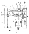
- a probe system may form part of the testing station and in the illustrated embodiment (as seen best in Figure 3) includes upper and lower side wall sensor assemblies 54a, 54b, upper and lower shoulder sensors (not shown) and a center tread sensor 58.
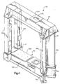
- the chuck apparatus including spindle assembly 410 and chuck assembly 310, loadwheel assembly 500 including loadwheel 510, tire grinders 50, 52, and probe system 56 are mounted to a gantry-like frame system indicated generally by the reference character 60 ( Figures 3 and 4).
- the frame includes a base 62, and a cross beam 64 supported a predetermined distance above the base by pairs of columns 66a, 66b and 68a, 68b.
- the base 62 comprises a pair of horizontal I-beams preferably welded together to form a unitary member.
- one end of the base 62 is configured as a "Y" (as viewed in plan) and includes end sections 70a, 70b, whereas an opposite end of the base 62 is configured as a "T” and includes cross beam 72.
- the frame 60 is described more fully in the aforementioned co-pending application relating to the overall tire testing system.
- the inlet conveyor 10 conveys tires to be tested from a centering station indicated generally by the reference character 100 to the testing station 12.
- a tire to be tested is delivered to the entrance of the centering station 100 by a belt or roller conveyor (not shown).
- Figure 1 illustrates a tire, indicated in phantom by the reference character 102, about to be delivered to the inlet conveyor.
- the inlet conveyor includes a feed or kick roll 108 which moves the delivered tire onto the inlet conveyor mechanism.
- a tire is delivered to the centering station 100 by the kick roll 108 and then is centered with respect to an axis indicated by the reference character 154.
- the centering axis 154 is located a fixed distance from a test station axis 156 ( Figures 1 and 2) which, in the preferred embodiment, corresponds to the rotational axis of the spindle assembly 410. Accordingly, after a tire is centered at the centering station 100 it is delivered so as to be in alignment with the spindle assembly. With this arrangement, the distance which the tire is moved from the centering station to the test station is the same for all tires regardless of their diameter.
- the conveyor unit Prior to receiving a tire at the centering station, the conveyor unit is lowered by the actuator 142. A tire is driven onto a conveyor by the inlet kick roll 108.
- the centering arm actuator (not shown) is actuated to drive centering arms 170, 172 toward the tire until the rollers 176, 176a engage the tire periphery. If a lubricator is present, one of the rollers 176a is rotated in order to rotate the tire at the centering station thereby enabling the lubricator to apply a lubricant to the tire 20.
- the conveyor unit is raised by actuator 142 thereby picking up the tire and, in effect, raising it above the support conveyor.
- Each roller 176, 176a is mounted such that it can be moved vertically a predetermined distance in order to accommodate relative movement between the tire and the centering arms 170, 172 as the conveyor assembly engages and lifts the tire.
- the centering arms are then moved outwardly to their retracted positions, and the tire to be tested is supported by the conveyor unit and centered with respect to the axis 154; the tire also is located a predetermined distance from the axis 156 of the spindle assembly 410.
- the conveyor then is actuated to advance the tire a predetermined distance which positions the tire coincident with the axis 156 of the spindle 410.
- the actuator 142 then is activated to lower the conveyor unit which, in effect, lowers the tire onto the spindle.
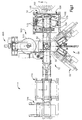
- loadwheel assembly 500 can be characterized as comprising three main components, namely, loadwheel 510, C-shaped carriage 550, and drive mechanism 600.
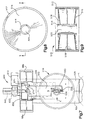
- the loadwheel 510 includes a cylindrical outer wall 512 the exterior surface of which contacts the rotating tire held by the chuck assembly, as is known in the art.
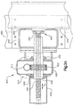
- outer wall 512 of loadwheel 510 is connected to a hub 514 defining a hollow bore 520, as best seen in Figure 8 (which does not show the loadwheel spindles).
- Hub 514 is joined to outer wall 512 by a plurality of solid, annular discs 516, 518.
- discs 516 are disposed between the hub 514 and outer wall 512 near the opposite ends thereof closing off the hollow interior of the loadwheel, while disc 518 is disposed between the central portions of hub 514 and wall 512.
- the discs 516, 518 support the outer wall 512 around the entire periphery thereof.
- This construction results in consistent, precise measurement of the forces exerted by the rotating tire against wall 512 due to there being no areas of the wall unsupported, as the discs engage the entire interior thereof.
- Prior art loadwheels include spokes or ribs extending between the hub and outer wall so as to support the wall at spaced locations, resulting in areas between these locations being more susceptible to deflection under load of the tire. Consequently, as the rotating tire contacts the prior art loadwheel, the forces transferred from the outer wall to the spindles (equipped with the load cells) may vary over the circumference of the wheel, which may generate electrical signals not truly representative of the location or magnitude of irregularities in the tire.
- the loadwheel of the invention accurately senses the forces exerted by the tire so as to precisely detect any irregularities therein. Additionally, unlike the prior art, the loadwheel of the invention does not suffer from harmonic related problems caused by the spoked construction of some prior art loadwheels.
- discs 516, 518 engage the wall 512 around the entire periphery thereof, it will be recognized that the inventive concept involves supporting the wall at substantially its entire periphery. Further, it should be appreciated that the number and exact positioning of discs which support the outer wall of the loadwheel may be varied without departing from the teachings of the invention. For example, the center disc 518 may be omitted as long as the remaining disc or discs sufficiently supports the wall of the loadwheel during testing so that the load cells generate accurate signals corresponding to irregularities in the tire.
- outer discs 516 preferably are conically-shaped members which diverge from each other in a direction extending from hub 514 toward outer wall 512.
- the loadwheel 510 preferably is formed as a weldment, i.e., a welded assembly comprising the hub, outer wall, and discs.
- the loadwheel is an aluminum weldment. Forming the loadwheel as a weldment rather than a casting (as in the prior art) reduces manufacturing cost while providing a structurally rigid component.
- materials other than aluminum may be used to form the loadwheel 510.
- the loadwheel need not necessarily be formed as a welded assembly, although that is preferred for reasons of reduced cost.
- An advantage of the invention is that conventional testing machines may be retrofitted to include the improved loadwheel.
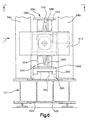
- C-shaped carriage 550 is shown to include an upper horizontal leg 552, a lower horizontal leg 554, and a vertical connecting leg 556 extending therebetween.
- the end portions 553, 555 of carriage legs 552, 554 are formed to include stepped or recessed areas ( Figure 7) attached to (or alternatively formed integrally with) mounting pads 558, 560.
- Pads 558, 560 mount the spindles 522, 524 of loadwheel 510 and the load cells 530, 540.
- the manner in which the spindles and load cells are affixed to the carriage legs is known in the art and thus will not be discussed in detail herein.
- the ends of hub 514 are provided with threaded holes for securing end plates having bearings via which the loadwheel 510 rotates about the spindles, as is conventional.
- load cells 530, 540 are accessible only from the side of each carriage leg provided with the mounting pad (i.e., the side indicated by arrow L).
- the invention permits the carriage 550 to be mounted to the machine frame 60 ( Figure 4) in two different positions so that the mounting pads of the carriage legs can face either side of the machine, thereby overcoming load cell accessibility problems present in prior art machines.
- outer surfaces 562, 564 of upper and lower carriage legs 552, 554 are provided with mounting plates 566, 568.
- Each mounting plate may be detachably secured to a guide piece 580 configured to slidably mate with a support 590.
- the support 590 is fixed to beam 72 of machine frame 60 by any suitable fastening means 592, such as screws, bolts, a welded connection, etc.
- guide piece 580 is attached to either mounting plate 566 or 568 via any suitable connection which permits detachment of the guide piece 580, such as threaded connectors which may easily be disconnected to allow guide piece 580 to be attached to the other mounting plate.
- the guide piece 580 and support 590 cooperate to facilitate sliding of the carriage 550 toward and away from the tire.
- the guide piece 580 and support 590 are formed with mating dovetail portions which lock the respective components in position while permitting the carriage 550 and loadwheel 510 to slide relative to the tire held by the chuck assembly. While a dovetail connection between the guide piece 580 and support 590 is the preferred means of slidably connecting the components, it should be appreciated that alternative connections may be used to secure the carriage in position while allowing movement of same toward or away from the tire.
- the carriage 550 is mounted such that the load cells 530, 540 are accessible from the left side of the carriage (when viewing the carriage head on as in Figure 6).
- the load cells for maintenance or replacement purposes, one must approach the carriage from the left side of the machine (in the direction of arrow L).
- prior art loadwheel assemblies are inadequate in that the carriage was securable to the frame in only one position. This caused considerable difficulty when it became time to replace the load cells, for example, by requiring removal of one or more system components to allow unimpeded access to the load cells.
- carriage 550 is provided with means for permitting its mounting in alternate positions.
- the carriage In order to mount the carriage such that the load cells 530, 540 are accessible from the side opposite that shown in Figure 6, the carriage is disconnected from drive mechanism 600 and removed from the machine frame by sliding guide piece 580 off support 590.
- the guide piece 580 then is detached from mounting plate 568 and attached to mounting plate 566.
- the entire carriage 550 is rotated 180° along an axis perpendicular to the arrow L (i.e., along an axis passing into the plane of figure 6).
- the guide piece 580 then is slid onto support 590 and attached to drive mechanism 600.
- the resulting arrangement has load cells 530, 540 located on the opposite side of the machine from that shown in Figure 6, with loadwheel 510 remaining in the same position. Accordingly, the invention permits the carriage 550 to be selectively mounted such that the load cells are accessible from either side of the machine frame. This feature constitutes a considerable improvement over prior art assemblies which limited access to the load cells to only one side of the carriage and frame.
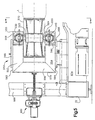
- FIGs 3 and 3A show the carriage 550 in a retracted position relative to frame 60 in which the loadwheel 510 does not engage tire 20.
- mechanism 600 comprises motor 610 having an output shaft 612 connected to a gearbox 620 provided with one or more gears 622 which step down the rotational output of motor 610.
- the gear 622 is fixed to a female member 630 preferably in the form of a threaded sleeve which is free to rotate within suitable bearings or bushings 630, 632, but whose position is otherwise fixed.
- a threaded male member 640 preferably in the form of a ball screw is received within sleeve 630 and is driven laterally (i.e., to the left and right in Figure 3A) upon rotation of screw 630.
- One end 642 of screw 640 is attached to the outer surface 570 of carriage leg 556 via a clamping assembly 660; thus, movement of screw 640 results in movement of carriage 550 and loadwheel 510 carried thereby.
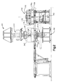
- Figure 5 shows (in somewhat exaggerated fashion) the carriage displaced from the frame columns such that the loadwheel engages the tire.
- a housing 644 preferably is attached to gearbox 620 and encloses the opposite end of ball screw 640 as well as a corresponding end of threaded sleeve 630.
- a box frame 650 preferably is fixed to frame column 68b by a flange or bracket portion 652 to enclose the end 642 of screw 640 and adjacent structure.
- the motor 610 and gearbox 620 are integrated with and directly engage and rotate threaded sleeve 630 to drive screw 640 and carriage 550 toward and away from tire 20.
- the drive mechanism 600 provides a simplified structure as compared with prior art machines which typically include a motion transmitting device, e.g. a chain and sprocket assembly, disposed between the motor and the carriage. As such, the mechanism of the invention is less susceptible to breakdown than that of the prior art and, in addition, requires less maintenance due to the reduced number of components.
- the invention also may be equipped with means for detecting and monitoring the distance the carriage 550 is displaced from machine frame 60.
- a sensor 670 is fixed to frame 60 and includes a string 672 one end of which is attached to carriage 550 as indicated at 674.
- Sensor 670 thus monitors the position of carriage 550 and loadwheel 510 carried thereon and generates an electrical signal that is fed to a suitable system control such as a microprocessor (not shown) which controls movement of the loadwheel to its proper position.
Description
The
The foregoing detailed description of preferred embodiments is made for purposes of providing a complete disclosure and should not be construed as limiting the scope and application of the inventive concepts disclosed herein, as many modifications and variations of the invention will be apparent to those skilled in the art.
Claims (14)
- A loadwheel assembly for contacting a load, in particular a rotating load, in particular for use in a tire testing machine, the assembly comprising:wherein the carriage (550) has first and second sides and the load cells are disposed so as to be accessible from one of said first and second sides of the carriage;a carriage (550);a loadwheel (510) rotatably mounted to the carriage (550), the loadwheel (510) including:first and second ends;a substantially cylindrical wall (512) extending between the first andsecond ends, the wall (512) having an outer surface adapted to be contacted by a load;a hub (514) spaced inwardly from the cylindrical wall (512);load cells (530, 540) on both sides of the loadwheel (510), the load cells (530, 540) generating a signal corresponding to a force exerted on the load wheel (510);
characterized by means (566, 568, 580, 590) for mounting the carriage (550) on a frame (60) with the carriage (550) side including the load cells (530, 540) selectively facing one of a plurality of directions to allow the load cells (530, 540) to be accessed from different directions. - A loadwheel assembly according to claim 1 wherein a pair of annular support plates (516) is disposed between the hub (514) and the cylindrical wall (512) adjacent the first and second ends and supporting the cylindrical wall (512) around substantially the entire periphery thereof, and wherein
the support plates (516) are conically-shaped and diverge in a direction extending away from the hub (514) and toward the cylindrical wall (512) of the loadwheel (510). - A loadwheel assembly according to claim 2, wherein the support plates (516) are close off the ends of the loadwheel (510) to define a hollow interior therebetween.
- A loadwheel assembly according to claim 2 or 3, the loadwheel further comprising at least one additional annular support plate (518) disposed between said pair of conically-shaped support plates (516) and extending from a central portion of the hub (514) toward a central portion of the cylindrical wall (512).
- A loadwheel assembly according to anyone of the preceding claims, the loadwheel (510) further comprising spindles (522, 524) attached to the carriage (550) and located adjacent to the hub (514) on both sides of the loadwheel (510), the spindles (522, 524) carrying the load cells (530, 530) and rotatably supporting the loadwheel.
- A loadwheel assembly according to claim 5, wherein the carriage (550) is generally C-shaped with upper and lower legs (552, 554) joined by a connecting leg (556), the spindles (522, 524) respectively secured to the upper and lower legs of the carriage (550) and rotatably supporting the loadwheel (510).
- A loadwheel assembly according to anyone of the preceding claims, wherein the carriage (550) is mounted to a frame (60) and is movable along the frame (60).
- A loadwheel assembly according to claim 7, wherein the carriage (550) is secured to a slide member (580) with a dovetail portion disposed in a complementarily configured portion (590) of said frame (60).
- A loadwheel assembly according to claim 7, wherein the carriage (550) has a plurality of mounting brackets (566, 568) provided at different locations on the carriage (550) and the slide member (580) is detachably securable to any one of the mounting brackets (566, 568).
- A loadwheel assembly according to claim 7, 8 or 9, further comprising a motor (610) with an output shaft (612), a threaded female member (630) coupled to and rotated by the output shaft (612), a threaded male member (640) attached to the carriage (550) and received within the female member (630) so as to be linearly movable relative thereto, wherein the motor (610) rotates the threaded female member (630) to move the threaded male member (640) and carriage (550) in a substantially linear direction relative to the frame (60).
- A loadwheel assembly according to claim 10, wherein the threaded female member (630) is a cylindrical sleeve with threads on an interior surface thereof, and the threaded male member (640) is a ball screw, and the motor shaft (612) drives a gear (622) directly connected to the cylindrical sleeve (630).
- A loadwheel assembly according to anyone of claims 7 to 11, further comprising means (600) for moving the carriage (550) along the frame (60).
- A loadwheel assembly according to anyone of claims 4 to 12, wherein the three plates (516, 518) are spaced along a length of the hub (514).
- A loadwheel assembly according to anyone of the preceding claims, wherein the loadwheel (510) comprises a welded assembly.
Applications Claiming Priority (3)
| Application Number | Priority Date | Filing Date | Title |
|---|---|---|---|
| US3671797P | 1997-01-24 | 1997-01-24 | |
| US36717P | 1997-01-24 | ||
| PCT/US1998/001325 WO1998034800A2 (en) | 1997-01-24 | 1998-01-22 | Loadwheel assembly for tire testing systems |
Publications (3)
| Publication Number | Publication Date |
|---|---|
| EP0954452A2 EP0954452A2 (en) | 1999-11-10 |
| EP0954452A4 EP0954452A4 (en) | 2000-07-05 |
| EP0954452B1 true EP0954452B1 (en) | 2004-05-06 |
Family
ID=21890214
Family Applications (1)
| Application Number | Title | Priority Date | Filing Date |
|---|---|---|---|
| EP98903683A Expired - Lifetime EP0954452B1 (en) | 1997-01-24 | 1998-01-22 | Loadwheel assembly for tire testing systems |
Country Status (11)
| Country | Link |
|---|---|
| US (1) | US5979231A (en) |
| EP (1) | EP0954452B1 (en) |
| JP (3) | JP4008501B2 (en) |
| KR (1) | KR100313608B1 (en) |
| CN (1) | CN1145561C (en) |
| AU (1) | AU720694B2 (en) |
| BR (1) | BR9806992A (en) |
| CA (1) | CA2278562C (en) |
| DE (1) | DE69823646T2 (en) |
| ES (1) | ES2219870T3 (en) |
| WO (1) | WO1998034800A2 (en) |
Families Citing this family (19)
| Publication number | Priority date | Publication date | Assignee | Title |
|---|---|---|---|---|
| US6834559B1 (en) | 1999-07-09 | 2004-12-28 | Illinois Tool Works Inc. | Vibration compensation system for tire testing systems |
| US6915684B2 (en) * | 2002-04-22 | 2005-07-12 | Illinois Tool Works, Inc. | Tire uniformity testing |
| JP4339048B2 (en) * | 2003-08-25 | 2009-10-07 | 国際計測器株式会社 | Tire uniformity measuring method and apparatus, and tire correcting method and apparatus |
| US7197920B2 (en) * | 2005-04-05 | 2007-04-03 | Ford Global Technologies, Llc | Test apparatus for accelerated wheel and suspension component structural durability |
| KR101230627B1 (en) * | 2010-07-06 | 2013-02-15 | 세림테크주식회사 | Correcting apparatus for tire uniformity and correcting method using that |
| US8347702B2 (en) * | 2010-08-04 | 2013-01-08 | The Pullman Company | Tracked vehicle track backer pad and road wheel tire test machine and method |
| JP5225370B2 (en) * | 2010-12-24 | 2013-07-03 | 株式会社神戸製鋼所 | Calibration method for multi-component force detector in rolling resistance tester |
| CN102279111B (en) * | 2011-08-31 | 2012-12-19 | 吉林大学 | Rotary table sideslip type lane-changeable tire mechanical characteristic tester |
| JP5752057B2 (en) | 2012-01-12 | 2015-07-22 | 三菱重工マシナリーテクノロジー株式会社 | Rim assembly and tire testing apparatus |
| KR101414013B1 (en) * | 2012-12-03 | 2014-07-02 | 한국타이어 주식회사 | Green tire shape compensation machine and shape compensation method |
| JP6087172B2 (en) * | 2013-03-05 | 2017-03-01 | 株式会社神戸製鋼所 | Tire testing machine |
| CN103278060A (en) * | 2013-05-27 | 2013-09-04 | 湖北汽车工业学院 | Comprehensive bounce detecting machine with disk hub |
| JP6005276B2 (en) * | 2013-06-14 | 2016-10-12 | 三菱重工マシナリーテクノロジー株式会社 | Tire conveyance method, tire conveyance fixing device, and tire inspection system |
| CN103438776B (en) * | 2013-09-16 | 2017-02-08 | 上海新世纪机器人有限公司 | Cover tyre jumping degree testing equipment |
| MX2017006958A (en) | 2014-12-02 | 2018-06-06 | Micro Poise Measurement Systems Llc | Tire uniformity testing system. |
| KR102020711B1 (en) | 2017-08-08 | 2019-09-11 | 주식회사 대화산기 | Wheel replacement device of tire uniformity testing machine |
| WO2019188109A1 (en) * | 2018-03-29 | 2019-10-03 | 株式会社神戸製鋼所 | Tire testing machine and tire marking method |
| JP2019174449A (en) * | 2018-03-29 | 2019-10-10 | 株式会社神戸製鋼所 | Tire test machine and tire marking method |
| CN114523808B (en) * | 2022-01-26 | 2024-01-30 | 东风柳州汽车有限公司 | Tire assembling centering device, tire assembling centering control method and control device |
Family Cites Families (51)
| Publication number | Priority date | Publication date | Assignee | Title |
|---|---|---|---|---|
| US2781119A (en) * | 1954-05-13 | 1957-02-12 | Jl Ferguson Co | Package aligning apparatus |
| US2771176A (en) * | 1955-02-25 | 1956-11-20 | United States Steel Corp | Conditioning device for bundles of coiled material |
| US3102627A (en) * | 1956-03-29 | 1963-09-03 | Internat Staple And Machine Co | Apparatus for centering cartons |
| US2901085A (en) * | 1958-12-08 | 1959-08-25 | Carando Machine Works | Elevating and centering device for cylindrical bodies |
| US3081959A (en) * | 1960-02-03 | 1963-03-19 | Akron Standard Engineers Ltd | Machines for feeding stock to type building machines |
| US3089576A (en) * | 1960-12-16 | 1963-05-14 | Signode Steel Strapping Co | Locating device |
| US3221364A (en) * | 1962-06-29 | 1965-12-07 | Akron Standard Mold Co | Take-off mechanism |
| US3244575A (en) * | 1962-07-30 | 1966-04-05 | Akron Standard Mold Co | Tire building apparatus |
| US3346434A (en) * | 1964-06-09 | 1967-10-10 | Akron Standard Mold Co | Tire building drum |
| CA1025695A (en) * | 1967-02-01 | 1978-02-07 | Clarence Hofelt (Jr.) | Means for correcting non-uniformity in tires |
| US3687260A (en) * | 1971-01-20 | 1972-08-29 | Potlatch Forests Inc | Edging picker |
| US3817003A (en) * | 1972-04-05 | 1974-06-18 | Gen Tire & Rubber Co | Harmonic composite grinding of tires |
| US3849942A (en) * | 1972-04-05 | 1974-11-26 | Gen Tire & Rubber Co | Harmonic composite grind |
| US3837689A (en) * | 1973-08-28 | 1974-09-24 | Akron Standard | Telescoping tube assembly |
| JPS548321B2 (en) * | 1973-10-08 | 1979-04-14 | ||
| DE2456835A1 (en) * | 1973-12-03 | 1976-01-02 | Fabricated Machine Co | Testing device for vehicle tyres - has two holding devices between which tyre is held to check uniformity and truth of rotation |
| US4078339A (en) * | 1974-11-18 | 1978-03-14 | Ongaro Dynamics, Inc. | Method for correcting rubber tires for forces generated by dynamic non-uniformities |
| US4024372A (en) * | 1975-12-19 | 1977-05-17 | Akron Standard, Division Of Eagle-Picher Industries, Inc. | Method of making a load cell |
| US4023407A (en) * | 1976-01-19 | 1977-05-17 | Akron Standard, Division Of Eagle-Picher Industries, Inc. | Chuck for tire uniformity machine |
| US4241300A (en) * | 1977-03-24 | 1980-12-23 | Eagle-Picher Industries, Inc. | Circuit responsive to rate change in amplitude of analog electrical signal for use in tire processing apparatus |
| US4191055A (en) * | 1978-07-25 | 1980-03-04 | Ransburg Corporation | Dynamic imbalance determining system |
| JPS57144442A (en) * | 1981-03-03 | 1982-09-07 | Kobe Steel Ltd | Correction method for measurement error of tire uniformity machine |
| GB2104010A (en) * | 1981-08-20 | 1983-03-02 | Froude Eng Ltd | >Tyre testing apparatus |
| US4458527A (en) * | 1981-11-27 | 1984-07-10 | Eagle-Picher Industries, Inc. | Apparatus for measuring the rolling resistance of tires |
| US4489598A (en) * | 1983-05-09 | 1984-12-25 | Eagle-Picher Industries, Inc. | Tire rolling resistance measurement system |
| US4576040A (en) * | 1983-06-29 | 1986-03-18 | Eagle-Picher Industries, Inc. | Device for measuring extraneous losses in apparatus for measuring the rolling resistance of tires |
| DE3406719A1 (en) * | 1984-02-24 | 1985-08-29 | Collmann GmbH & Co, Spezialmaschinenbau KG, 2400 Lübeck | TIRE POSITIONING DEVICE |
| US4723563A (en) * | 1986-07-29 | 1988-02-09 | Allied Automation Systems, Inc. | Wheel soaper |
| US4704900A (en) * | 1986-08-19 | 1987-11-10 | Eagle-Picher Industries, Inc. | Apparatus and method for imposing a desired average radial force on a tire |
| US4702287A (en) * | 1986-08-22 | 1987-10-27 | Eagle-Picher Industries, Inc. | Method and apparatus for controlling the automatic inflation of tires for testing |
| US4815004A (en) * | 1986-10-17 | 1989-03-21 | Eagle-Picher Industries, Inc. | Apparatus and method for predicting fore/aft forces generated by tires |
| KR960000995B1 (en) * | 1987-06-12 | 1996-01-15 | 이글 피쳐 인더스트리즈 인코포레이티드 | Apparatus and the method for improving uniformity measurement |
| US4785864A (en) * | 1988-02-26 | 1988-11-22 | Eagle-Picher Industries, Inc. | Rim mount for tire uniformity machine |
| US4846334A (en) * | 1988-02-29 | 1989-07-11 | Eagle-Picher Industries, Inc. | Conveyor for tire uniformity measurement machine |
| US4852398A (en) * | 1988-03-09 | 1989-08-01 | Eagle-Picher Industries, Inc. | Tire testing machine having adjustable bead width |
| JPH01253630A (en) * | 1988-04-01 | 1989-10-09 | Bridgestone Corp | Measurement of high speed uniformity of tire |
| US4885936A (en) * | 1988-09-26 | 1989-12-12 | Eagle-Picher Industries, Inc. | Automatic loadwheel cleaner |
| US4896531A (en) * | 1988-10-11 | 1990-01-30 | Eagle-Picher Industries, Inc. | Sidewall appearance monitor |
| US4870858A (en) * | 1988-10-21 | 1989-10-03 | Eagle-Picher Industries, Inc. | Tire testing machine |
| DE3919450A1 (en) * | 1989-06-14 | 1990-12-20 | Hofmann Gmbh & Co Kg Maschinen | MEASURING DEVICE FOR MEASURING PERIODICALLY CHANGING FORCES AND / OR MOMENTS ON ROTATING ROTORS |
| DE3922288C2 (en) * | 1989-07-06 | 1997-04-10 | Hofmann Gmbh & Co Kg Maschinen | Method and device for checking the uniformity of pneumatic tires, in particular vehicle tires |
| JPH03188348A (en) * | 1989-12-18 | 1991-08-16 | Kobe Steel Ltd | Adjusting apparatus for automatic rim-width of tire uniformity machine |
| US4976141A (en) * | 1990-03-05 | 1990-12-11 | Illinois Tool Works Inc. | Stepped rim for tire testing machine |
| US5029467A (en) * | 1990-03-12 | 1991-07-09 | Illinois Tool Works, Inc. | Hydraulic apparatus for tire uniformity machine |
| DE4014558A1 (en) * | 1990-05-07 | 1991-11-14 | Hofmann Maschinenbau Gmbh | IMPELLER FOR A TIRE TESTING MACHINE |
| JPH088432B2 (en) * | 1990-06-01 | 1996-01-29 | ソマール株式会社 | Substrate transfer device |
| US5111687A (en) * | 1990-11-26 | 1992-05-12 | Standards Testing Laboratories, Inc. | Roadwheel for tire testing apparatus |
| US5390540A (en) * | 1992-01-31 | 1995-02-21 | Akron Special Machinery, Inc. | Control apparatus for the uniformity machine |
| US5481907A (en) * | 1993-12-13 | 1996-01-09 | Mts Systems Corporation | Tire testing system having focused links reducing cosine errors |
| US5566816A (en) * | 1994-10-11 | 1996-10-22 | Illinois Tool Works Inc. | Conveying and centering apparatus |
| JP3257617B2 (en) * | 1995-06-15 | 2002-02-18 | 三菱電機株式会社 | Vehicle output measuring device and method |
-
1997
- 1997-12-10 US US08/988,509 patent/US5979231A/en not_active Expired - Lifetime
-
1998
- 1998-01-22 CA CA002278562A patent/CA2278562C/en not_active Expired - Lifetime
- 1998-01-22 DE DE69823646T patent/DE69823646T2/en not_active Expired - Lifetime
- 1998-01-22 ES ES98903683T patent/ES2219870T3/en not_active Expired - Lifetime
- 1998-01-22 JP JP53474198A patent/JP4008501B2/en not_active Expired - Lifetime
- 1998-01-22 EP EP98903683A patent/EP0954452B1/en not_active Expired - Lifetime
- 1998-01-22 AU AU60388/98A patent/AU720694B2/en not_active Ceased
- 1998-01-22 WO PCT/US1998/001325 patent/WO1998034800A2/en active IP Right Grant
- 1998-01-22 BR BR9806992-6A patent/BR9806992A/en not_active IP Right Cessation
- 1998-01-22 CN CNB988018195A patent/CN1145561C/en not_active Expired - Lifetime
-
1999
- 1999-07-12 KR KR1019997006304A patent/KR100313608B1/en not_active IP Right Cessation
-
2007
- 2007-06-05 JP JP2007149791A patent/JP2007279058A/en not_active Withdrawn
-
2011
- 2011-02-28 JP JP2011042783A patent/JP2011107162A/en active Pending
Also Published As
| Publication number | Publication date |
|---|---|
| KR100313608B1 (en) | 2001-11-16 |
| AU6038898A (en) | 1998-08-26 |
| JP2001511254A (en) | 2001-08-07 |
| ES2219870T3 (en) | 2004-12-01 |
| EP0954452A4 (en) | 2000-07-05 |
| JP2007279058A (en) | 2007-10-25 |
| DE69823646T2 (en) | 2004-09-30 |
| CA2278562C (en) | 2004-04-27 |
| CN1145561C (en) | 2004-04-14 |
| AU720694B2 (en) | 2000-06-08 |
| WO1998034800A3 (en) | 1998-11-19 |
| JP4008501B2 (en) | 2007-11-14 |
| EP0954452A2 (en) | 1999-11-10 |
| CN1243478A (en) | 2000-02-02 |
| KR20000070083A (en) | 2000-11-25 |
| JP2011107162A (en) | 2011-06-02 |
| WO1998034800A2 (en) | 1998-08-13 |
| DE69823646D1 (en) | 2004-06-09 |
| CA2278562A1 (en) | 1998-08-13 |
| US5979231A (en) | 1999-11-09 |
| BR9806992A (en) | 2000-03-14 |
Similar Documents
| Publication | Publication Date | Title |
|---|---|---|
| EP0954452B1 (en) | Loadwheel assembly for tire testing systems | |
| EP0954451B1 (en) | Tire uniformity testing system | |
| EP0954747B1 (en) | Inlet conveyor for tire testing systems | |
| US5992227A (en) | Automatic adjustable width chuck apparatus for tire testing systems | |
| US4787150A (en) | Fixture for checking the alignment of a loadwheel with the spindle of a tire uniformity machine | |
| CN220819317U (en) | Coil measuring equipment for spinning | |
| CA2450794A1 (en) | Inlet conveyor for tire testing systems | |
| CA1292867C (en) | Loadwheel alignment fixture |
Legal Events
| Date | Code | Title | Description |
|---|---|---|---|
| PUAI | Public reference made under article 153(3) epc to a published international application that has entered the european phase |
Free format text: ORIGINAL CODE: 0009012 |
|
| 17P | Request for examination filed |
Effective date: 19990724 |
|
| AK | Designated contracting states |
Kind code of ref document: A2 Designated state(s): DE ES FR GB IT |
|
| RIN1 | Information on inventor provided before grant (corrected) |
Inventor name: QUINN, CHRISTY Inventor name: REYNOLDS, DENNIS, ALLYN Inventor name: NEIFERD, KEITH, A. Inventor name: JELLISON, FRANK, R. Inventor name: CUKELJ, RICHARD, J. Inventor name: BORMET, FRANCIS, J. Inventor name: LEES, DAVID, W., SR. |
|
| A4 | Supplementary search report drawn up and despatched |
Effective date: 20000523 |
|
| AK | Designated contracting states |
Kind code of ref document: A4 Designated state(s): DE ES FR GB IT |
|
| RIC1 | Information provided on ipc code assigned before grant |
Free format text: 7B 60C 25/00 A, 7G 01M 17/02 B |
|
| 17Q | First examination report despatched |
Effective date: 20020502 |
|
| GRAP | Despatch of communication of intention to grant a patent |
Free format text: ORIGINAL CODE: EPIDOSNIGR1 |
|
| GRAS | Grant fee paid |
Free format text: ORIGINAL CODE: EPIDOSNIGR3 |
|
| GRAA | (expected) grant |
Free format text: ORIGINAL CODE: 0009210 |
|
| AK | Designated contracting states |
Kind code of ref document: B1 Designated state(s): DE ES FR GB IT |
|
| REG | Reference to a national code |
Ref country code: GB Ref legal event code: FG4D |
|
| REF | Corresponds to: |
Ref document number: 69823646 Country of ref document: DE Date of ref document: 20040609 Kind code of ref document: P |
|
| REG | Reference to a national code |
Ref country code: ES Ref legal event code: FG2A Ref document number: 2219870 Country of ref document: ES Kind code of ref document: T3 |
|
| ET | Fr: translation filed | ||
| PLBE | No opposition filed within time limit |
Free format text: ORIGINAL CODE: 0009261 |
|
| STAA | Information on the status of an ep patent application or granted ep patent |
Free format text: STATUS: NO OPPOSITION FILED WITHIN TIME LIMIT |
|
| 26N | No opposition filed |
Effective date: 20050208 |
|
| REG | Reference to a national code |
Ref country code: GB Ref legal event code: 732E |
|
| REG | Reference to a national code |
Ref country code: FR Ref legal event code: TP |
|
| REG | Reference to a national code |
Ref country code: ES Ref legal event code: PC2A |
|
| REG | Reference to a national code |
Ref country code: FR Ref legal event code: PLFP Year of fee payment: 18 |
|
| REG | Reference to a national code |
Ref country code: FR Ref legal event code: PLFP Year of fee payment: 19 |
|
| REG | Reference to a national code |
Ref country code: FR Ref legal event code: PLFP Year of fee payment: 20 |
|
| PGFP | Annual fee paid to national office [announced via postgrant information from national office to epo] |
Ref country code: FR Payment date: 20170125 Year of fee payment: 20 Ref country code: DE Payment date: 20170125 Year of fee payment: 20 |
|
| PGFP | Annual fee paid to national office [announced via postgrant information from national office to epo] |
Ref country code: GB Payment date: 20170127 Year of fee payment: 20 |
|
| PGFP | Annual fee paid to national office [announced via postgrant information from national office to epo] |
Ref country code: IT Payment date: 20170124 Year of fee payment: 20 Ref country code: ES Payment date: 20170126 Year of fee payment: 20 |
|
| REG | Reference to a national code |
Ref country code: DE Ref legal event code: R071 Ref document number: 69823646 Country of ref document: DE |
|
| REG | Reference to a national code |
Ref country code: GB Ref legal event code: PE20 Expiry date: 20180121 |
|
| PG25 | Lapsed in a contracting state [announced via postgrant information from national office to epo] |
Ref country code: GB Free format text: LAPSE BECAUSE OF EXPIRATION OF PROTECTION Effective date: 20180121 |
|
| REG | Reference to a national code |
Ref country code: ES Ref legal event code: FD2A Effective date: 20180508 |
|
| PG25 | Lapsed in a contracting state [announced via postgrant information from national office to epo] |
Ref country code: ES Free format text: LAPSE BECAUSE OF EXPIRATION OF PROTECTION Effective date: 20180123 |