EP0954371B1 - Improved microporous membrane filtration assembly - Google Patents
Improved microporous membrane filtration assembly Download PDFInfo
- Publication number
- EP0954371B1 EP0954371B1 EP97946710A EP97946710A EP0954371B1 EP 0954371 B1 EP0954371 B1 EP 0954371B1 EP 97946710 A EP97946710 A EP 97946710A EP 97946710 A EP97946710 A EP 97946710A EP 0954371 B1 EP0954371 B1 EP 0954371B1
- Authority
- EP
- European Patent Office
- Prior art keywords
- filter
- feed
- housing
- permeate
- assembly according
- Prior art date
- Legal status (The legal status is an assumption and is not a legal conclusion. Google has not performed a legal analysis and makes no representation as to the accuracy of the status listed.)
- Expired - Lifetime
Links
- 238000005374 membrane filtration Methods 0.000 title 1
- 239000012982 microporous membrane Substances 0.000 title 1
- 239000012466 permeate Substances 0.000 claims description 39
- 239000012530 fluid Substances 0.000 claims description 27
- 239000000835 fiber Substances 0.000 claims description 15
- 238000004891 communication Methods 0.000 claims description 9
- 230000000712 assembly Effects 0.000 claims description 6
- 238000000429 assembly Methods 0.000 claims description 6
- 239000000356 contaminant Substances 0.000 claims description 6
- 230000002093 peripheral effect Effects 0.000 claims description 6
- 238000011001 backwashing Methods 0.000 claims description 5
- 238000011010 flushing procedure Methods 0.000 claims description 4
- 238000000034 method Methods 0.000 claims description 4
- 238000012856 packing Methods 0.000 claims description 4
- 238000009295 crossflow filtration Methods 0.000 claims description 3
- 230000008569 process Effects 0.000 claims description 3
- 238000002955 isolation Methods 0.000 claims 1
- 239000012510 hollow fiber Substances 0.000 description 13
- 239000012528 membrane Substances 0.000 description 11
- 238000001914 filtration Methods 0.000 description 7
- 239000000706 filtrate Substances 0.000 description 4
- 239000000463 material Substances 0.000 description 4
- 239000011347 resin Substances 0.000 description 4
- 229920005989 resin Polymers 0.000 description 4
- 238000000926 separation method Methods 0.000 description 4
- 238000005516 engineering process Methods 0.000 description 3
- 230000035699 permeability Effects 0.000 description 3
- 238000012360 testing method Methods 0.000 description 3
- JOYRKODLDBILNP-UHFFFAOYSA-N Ethyl urethane Chemical compound CCOC(N)=O JOYRKODLDBILNP-UHFFFAOYSA-N 0.000 description 2
- 238000003491 array Methods 0.000 description 2
- 238000010276 construction Methods 0.000 description 2
- 238000013461 design Methods 0.000 description 2
- 238000010408 sweeping Methods 0.000 description 2
- 230000009471 action Effects 0.000 description 1
- 230000015572 biosynthetic process Effects 0.000 description 1
- 230000000903 blocking effect Effects 0.000 description 1
- 239000000470 constituent Substances 0.000 description 1
- 238000000502 dialysis Methods 0.000 description 1
- 230000004907 flux Effects 0.000 description 1
- 238000005755 formation reaction Methods 0.000 description 1
- 238000009434 installation Methods 0.000 description 1
- 239000007788 liquid Substances 0.000 description 1
- 238000012423 maintenance Methods 0.000 description 1
- 238000000465 moulding Methods 0.000 description 1
- 230000000737 periodic effect Effects 0.000 description 1
- 238000004382 potting Methods 0.000 description 1
- 230000009467 reduction Effects 0.000 description 1
- 239000002990 reinforced plastic Substances 0.000 description 1
- 238000001223 reverse osmosis Methods 0.000 description 1
- 229910001220 stainless steel Inorganic materials 0.000 description 1
- 239000010935 stainless steel Substances 0.000 description 1
- 229920001187 thermosetting polymer Polymers 0.000 description 1
- 239000004634 thermosetting polymer Substances 0.000 description 1
- 238000000108 ultra-filtration Methods 0.000 description 1
Images


Classifications
-
- B—PERFORMING OPERATIONS; TRANSPORTING
- B01—PHYSICAL OR CHEMICAL PROCESSES OR APPARATUS IN GENERAL
- B01D—SEPARATION
- B01D65/00—Accessories or auxiliary operations, in general, for separation processes or apparatus using semi-permeable membranes
- B01D65/02—Membrane cleaning or sterilisation ; Membrane regeneration
-
- B—PERFORMING OPERATIONS; TRANSPORTING
- B01—PHYSICAL OR CHEMICAL PROCESSES OR APPARATUS IN GENERAL
- B01D—SEPARATION
- B01D63/00—Apparatus in general for separation processes using semi-permeable membranes
- B01D63/02—Hollow fibre modules
- B01D63/034—Lumen open in more than two directions
-
- B—PERFORMING OPERATIONS; TRANSPORTING
- B01—PHYSICAL OR CHEMICAL PROCESSES OR APPARATUS IN GENERAL
- B01D—SEPARATION
- B01D63/00—Apparatus in general for separation processes using semi-permeable membranes
- B01D63/02—Hollow fibre modules
- B01D63/04—Hollow fibre modules comprising multiple hollow fibre assemblies
- B01D63/043—Hollow fibre modules comprising multiple hollow fibre assemblies with separate tube sheets
-
- B—PERFORMING OPERATIONS; TRANSPORTING
- B01—PHYSICAL OR CHEMICAL PROCESSES OR APPARATUS IN GENERAL
- B01D—SEPARATION
- B01D2313/00—Details relating to membrane modules or apparatus
- B01D2313/54—Modularity of membrane module elements
-
- B—PERFORMING OPERATIONS; TRANSPORTING
- B01—PHYSICAL OR CHEMICAL PROCESSES OR APPARATUS IN GENERAL
- B01D—SEPARATION
- B01D2321/00—Details relating to membrane cleaning, regeneration, sterilization or to the prevention of fouling
- B01D2321/04—Backflushing
Definitions
- the present invention relates to filtration processes and apparatus of the kind using microporous membranes, wherein feed containing contaminant matter is applied under pressure to a feed receiving surface of the membrane for passage therethrough and wherein filtrate is withdrawn from the permeate side of the membranes.
- the invention relates to systems using microporous filters comprising elongate bundles of microporous polymeric fibres, wherein feed to be filtered is fed to the outside of the bundles of fibres and permeate is extracted from the ends of the fibre lumens.
- the systems also preferably incorporate a backwashing facility for periodic cleansing of the feed surfaces of the fibres.
- Typical prior art filter systems of the type described above generally include elongate tubular cartridges enclosing a bundle of the microporous hollow fibres. Manifold or header arrangements are then used to connect the cartridges, usually at one or both ends, these manifolds acting to separate and divert the respective flows of contaminated feed and permeate through the system, see e.g WO 91 16124 A .
- cross-flow systems typically have two feed manifolds (inlet and re-circulation outlet) and one or two permeate manifolds.
- the stream to be filtered flows tangential to or across the surface of the membrane. This generates a sweeping action at the membrane surface, keeping the surface cleaner.
- systems configured for dead end operations have only one feed inlet manifold and one permeate outlet manifold.
- these prior art manifolds or header arrangements are often configured to facilitate the construction of modular two or three dimensional cartridge arrays.
- US 4451369 describes a hollow fiber membrane-type fluid separation apparatus useful for selective separation of fluids in various techniques such as gas permeation, liquid permeation dialysis, ultrafiltration, reverse osmosis, etc., which comprises at least one pair of unit structures which are arranged uniaxially in series within a cylindrical pressure vessel, said pair of unit structures comprising a pair of cylindrical hollow fiber assemblies having a selective permeability, a means for collecting permeated fluid, which is held between side tube sheets provided each at a terminal of the pair of cylindrical hollow fiber assemblies and is capable of collecting the fluid which passes through the side tube sheet, a permeation fluid pipe for taking out the permeated fluid, which penetrates perpendicularly the means for collecting a permeated fluid at the center, and a fitting means provided with a passageway for passing a concentrated fluid being not permeated, said passageway being arranged at around central region of the means for collecting a permeated fluid so as to surround the permeation fluid pipe.
- US 5470469 describes a cartridge containing a plurality of hollow fiber membranes is disclosed.
- the cartridge comprises a plurality of fibers arranged in a bundle and at least one end of the bundle embedded in a tubesheet.
- the tubesheets are fitted with end caps to provide a chamber for the permeate.
- a feed tube extends longitudinally through the bundle and a permeate discharge tube is housed, preferably concentrically, within a feed tube.
- the cartridge does not require a high pressure seal, such as an O-ring seal, against the inner wall of the pressure vessel.
- the cartridge is configured as a single unit adapted for simple drop-in installation into a pressure vessel. Multiple cartridges may readily be inserted into a pressure vessel, and arranged so as to operate in series or in parallel.
- the hollow fiber membrane cartridge is adapted for industrial performance with high volumetric efficiency and high solute rejection.
- a process for installing the cartridges in a pressure vessel previously using spiral wound elements is disclosed.
- US 4670145 describes a fluid permeator apparatus which comprises an outer cylindrical shell having disposed therein a generally concentric outer central tube in communication with a port at one end of the cylindrical shell and a port at the opposite end of the cylindrical shell which is in communication with an inner central tube located within the outer central tube.
- the outer central tube is perforated so as to render it in communication with the outer surface.
- a plurality of permeator hollow fiber bundles having annular cross sections are removably mounted on the outer central tube.
- the hollow fibers are mounted with their open ends in at least one tube-sheet which is in communication with the inner central tube.
- the cylindrical shell has an additional port for feeding fluid to be separated or removing residue.
- EP 053635 describes a hollow fiber assembly having selective permeability by cylindrical arrangements of hollow fibers having selective permeability mainly comprising a cylindrical layer of hollow fibers (1) formed by crisscross arrangement of hollow fibers, a hollow portion (2) which exists inside the above cylindrical layer of hollow fibers (1), a plurality of engaging members (3) which are respectively separated from one another in said hollow portion (2), a resin wall (A) (4) which is disposed at an open end of said hollow fibers and arranged to be open to the exterior without leaving any space between said fibers and with separation from said engaing means (3), a resin wall (B) (5) which is disposed at the other end of said assembly for fixing the end of said assembly, an elastic supporting member 6 for controlling the distance between the two resin walls (A) (4) and (B) (5), and a fluid supply conduit (8).
- cartridge casings and header manifold structures need to be made from high strength, and thereby correspondingly high cost, materials such as stainless steel and higher grade reinforced plastic materials specifically designed to withstand these pressures.
- a filter assembly comprising: an elongate housing having two or more discrete filter bundle lengths disposed end to end in a series configuration, each filter bundle comprising a multitude of microporous polymeric hollow fibres, wherein feed to be filtered is fed to the outside of the bundle of fibres and permeate is extracted from one or both discharge ends of the fibre lumens; one or more feed passages extending longitudinally along said housing to direct feed to said filter bundle lengths; one or more longitudinally extending permeate return passages extending generally parallel to said filter bundle lengths, said permeate return passages being sealed from contact with said feed and adapted to be in fluid flow communication with each of said permeate discharge ends of said fibre lumens in said filter bundle lengths; and one or more manifold arrangements, each having a feed inlet port connecting with said one or more longitudinally extending feed passages and a separate permeate outlet port connected with said one or more permeate return passages; and wherein each longitudinal length of said housing
- the manifold arrangements are disposed at one or both longitudinal ends of said housing and are configured to connect a plurality of the filter assemblies into banks.
- the housing can include two, three or four filter bundle lengths disposed end to end in a series configuration.
- co-extensive filter bundle lengths are interconnected as a subassembly of multiple filter bundle lengths.
- each bundle length is separately potted in the conventional manner described in more detail hereafter.
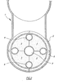
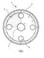
- the invention provides an elongate housing containing at any one point four co-extensive filter bundles with three or four such filter bundle lengths connected in series.
- a peripheral feed passage is provided that is generally parallel to the external walls of the housing that is desirably no more than about 15mm in radial depth at any point, together with a central feed passage that passes through the centre of the four co-extensive filter bundle lengths.
- the peripheral feed passage and/or central feed passage may be configured, by the use of packing material for example, to assist in directing the flow of feed both around and into the filter bundles.
- Manifold arrangements in the form of headers are preferably provided at both longitudinal ends of the housing to facilitate cross-flow filtration, wherein a portion of the feed can be discharged from the other end for recirculation.
- the feed outlet port can also be used as a flushing fluid inlet port for operation during the backwashing process, wherein fluid under pressure is applied to the inner surface of the fibre lumens via the filtrate or permeate outlet ports and a backwashing fluid is subsequently applied to the external surfaces of the fibres to flush out any accumulated contaminants that may have been dislodged from the fibres.
- other preferred forms of the invention could also include means to isolate individual filter assemblies or banks of assemblies in the event of failure of a filter bundle. This is achieved in one embodiment by means of individual valves associated with each filter bundle length, filter assembly housing, or manifold arrangement, as required.
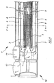
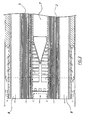
- the filter assembly 1 includes an elongate housing 2 having therein a plurality of filter bundles 3 disposed end to end in a series configuration.
- a plurality of filter bundles 3 disposed end to end in a series configuration.
- a similar arrangement is shown in Figure 5 utilising only three co-extensive filter bundles. At this stage, the use of either two or four co-extensive filter bundles lengths is preferred.
- Each filter bundle comprises a multitude of micro-porous polymeric hollow fibres of the kind wherein feed to be filtered is fed to the outside of the bundle of fibres and permeate is extracted from one or both permeate discharge ends of the fibre lumens.
- These bundles are usually "potted" at the discharge ends to readily facilitate separation of the permeate from the feed and simultaneously retain the fibres in assembled bundles.
- the preferred potting material is urethane, which is a thermo setting polymer.
- a shallow pre-pot tray is provided in the final peripheral shape required, that has a plurality of long spaced apart spikes. The fibres are arranged in the tray and the resin is cast, blocking off the fibre lumens at the end. The pre-pot trays are then removed and the bundle is placed into a centrifuge with second pot moulds, and additional urethane is introduced via the holes in the pre-pot moulding formed by the spikes. Once the second pot has cured, the pre-pot end section plus a section of the second pot is sliced off, thereby clearly exposing the ends of the fibre lumens.
- the feed passages comprise a generally annular outer feed passage 6 (of preferably no more than about 15mm) that extends around the periphery of the groups of filter bundles 3 and a central feed passage 7 that extends through the central core of the housing.
- the bundles have an outer casing including packing means that extends up to the periphery of the outer housing, the casing including means to direct the flow of feed both around and into the filter bundles.
- the central feed passage may similarly include formations in the form of baffles and the like for diverting the feed both into and around the filter bundles as shown in Figure 3.
- One or more longitudinally extending permeate return passages 8 are also provided which similarly extend parallel to the filter bundles, each of the permeate return passages being in fluid flow communication with each of the permeate discharge ends of the fibre lumens via connecting passages 9 (see Figure 1).
- Means in the form of valves or the like may also be provided (not shown) for selectively isolating an individual filter bundle, filter assembly housing, or manifold arrangement in the event of failure.
- each housing 2 Disposed at one or both longitudinal ends of each housing 2 is a manifold or header arrangement shown generally at 10.
- Each header includes a feed inlet port 11 that is in fluid flow communication with the longitudinally extending feed passages 6 and 7, and a permeate outlet port 12 which is in sealed and separate communication with the permeate return passages 8.
- the system operates in substantially the same manner as the prior art filtration processes.
- the system outlet is shut off and fluid is applied under pressure to the permeate to discharge outlet in a manner whereby it is passed through the membranes to dislodge contaminants that have accumulated on the outer feed surfaces.
- a flushing fluid which is often feed, is then usually applied to the cross-flow feed outlet port for passage through the system so as to flush out any dislodged contaminant matter.
- the system according to the invention provides a means of substantially increasing the packing density of the filter fibre bundles whilst simultaneously reducing the overall cost of the system by minimising the number of expensive header arrangements and connecting pipe work.
- experimentation carried out by the applicant has indicated that the present invention can result in a system that is 40% less expensive and 60% smaller than a plant employing the applicants current M10C technology.
- the present invention enables a significant reduction in backwash volume as compared to the applicants M10G technology particularly with respect to the sweep stage, as in theory at least, the same volume of sweeping fluid is required to flush out dislodged contaminants for four bundles in series, as is required for only one bundle. It also appears that the system of the invention is potentially capable of higher flow rates for a given physical size than most of the relevant prior art systems.
Landscapes
- Chemical & Material Sciences (AREA)
- Chemical Kinetics & Catalysis (AREA)
- Separation Using Semi-Permeable Membranes (AREA)
- Filtering Materials (AREA)
Applications Claiming Priority (3)
| Application Number | Priority Date | Filing Date | Title |
|---|---|---|---|
| AUPO4125A AUPO412596A0 (en) | 1996-12-10 | 1996-12-10 | Improved microporous membrane filtration assembly |
| AUPO412596 | 1996-12-10 | ||
| PCT/AU1997/000835 WO1998025694A1 (en) | 1996-12-10 | 1997-12-09 | Improved microporous membrane filtration assembly |
Publications (3)
| Publication Number | Publication Date |
|---|---|
| EP0954371A1 EP0954371A1 (en) | 1999-11-10 |
| EP0954371A4 EP0954371A4 (en) | 2000-02-23 |
| EP0954371B1 true EP0954371B1 (en) | 2008-01-30 |
Family
ID=3798433
Family Applications (1)
| Application Number | Title | Priority Date | Filing Date |
|---|---|---|---|
| EP97946710A Expired - Lifetime EP0954371B1 (en) | 1996-12-10 | 1997-12-09 | Improved microporous membrane filtration assembly |
Country Status (9)
| Country | Link |
|---|---|
| US (1) | US6254773B1 (enExample) |
| EP (1) | EP0954371B1 (enExample) |
| JP (1) | JP3949728B2 (enExample) |
| KR (1) | KR100519690B1 (enExample) |
| CN (1) | CN1140323C (enExample) |
| AU (1) | AUPO412596A0 (enExample) |
| DE (1) | DE69738497T2 (enExample) |
| ES (1) | ES2297866T3 (enExample) |
| WO (1) | WO1998025694A1 (enExample) |
Families Citing this family (78)
| Publication number | Priority date | Publication date | Assignee | Title |
|---|---|---|---|---|
| AU721064B2 (en) * | 1996-12-20 | 2000-06-22 | Evoqua Water Technologies Llc | Scouring method |
| US20040232076A1 (en) * | 1996-12-20 | 2004-11-25 | Fufang Zha | Scouring method |
| US6641733B2 (en) * | 1998-09-25 | 2003-11-04 | U. S. Filter Wastewater Group, Inc. | Apparatus and method for cleaning membrane filtration modules |
| TWI222895B (en) | 1998-09-25 | 2004-11-01 | Usf Filtration & Separations | Apparatus and method for cleaning membrane filtration modules |
| AUPP985099A0 (en) * | 1999-04-20 | 1999-05-13 | Usf Filtration And Separations Group Inc. | Membrane filtration manifold system |
| AUPQ680100A0 (en) * | 2000-04-10 | 2000-05-11 | Usf Filtration And Separations Group Inc. | Hollow fibre restraining system |
| AUPR064800A0 (en) * | 2000-10-09 | 2000-11-02 | Usf Filtration And Separations Group Inc. | Improved membrane filtration system |
| AUPR094600A0 (en) * | 2000-10-23 | 2000-11-16 | Usf Filtration And Separations Group Inc. | Fibre membrane arrangement |
| AUPR143400A0 (en) * | 2000-11-13 | 2000-12-07 | Usf Filtration And Separations Group Inc. | Modified membranes |
| AUPR421501A0 (en) | 2001-04-04 | 2001-05-03 | U.S. Filter Wastewater Group, Inc. | Potting method |
| AUPR584301A0 (en) | 2001-06-20 | 2001-07-12 | U.S. Filter Wastewater Group, Inc. | Membrane polymer compositions |
| AUPR692401A0 (en) | 2001-08-09 | 2001-08-30 | U.S. Filter Wastewater Group, Inc. | Method of cleaning membrane modules |
| AUPR774201A0 (en) * | 2001-09-18 | 2001-10-11 | U.S. Filter Wastewater Group, Inc. | High solids module |
| DE60213184T2 (de) * | 2001-11-16 | 2007-06-28 | U.S. Filter Wastewater Group, Inc. | Methode zur Reinigung von Membranen |
| US7247238B2 (en) | 2002-02-12 | 2007-07-24 | Siemens Water Technologies Corp. | Poly(ethylene chlorotrifluoroethylene) membranes |
| ES2355615T3 (es) | 2002-04-26 | 2011-03-29 | Millipore Corporation | Dispositivo de transferencia de fluido estéril desechable. |
| AUPS300602A0 (en) | 2002-06-18 | 2002-07-11 | U.S. Filter Wastewater Group, Inc. | Methods of minimising the effect of integrity loss in hollow fibre membrane modules |
| US7938966B2 (en) | 2002-10-10 | 2011-05-10 | Siemens Water Technologies Corp. | Backwash method |
| AU2002953111A0 (en) | 2002-12-05 | 2002-12-19 | U. S. Filter Wastewater Group, Inc. | Mixing chamber |
| DE602004013731D1 (de) * | 2003-03-05 | 2008-06-26 | Hydranautics | Tauchbares membranmodul mit austauschbaren membranelementen |
| AU2003903507A0 (en) | 2003-07-08 | 2003-07-24 | U. S. Filter Wastewater Group, Inc. | Membrane post-treatment |
| US8268176B2 (en) | 2003-08-29 | 2012-09-18 | Siemens Industry, Inc. | Backwash |
| AU2004289373B2 (en) | 2003-11-14 | 2010-07-29 | Evoqua Water Technologies Llc | Improved module cleaning method |
| US7293477B2 (en) | 2003-12-23 | 2007-11-13 | Millipore Corporation | Disposable, pre-sterilized fluid receptacle sampling device |
| WO2005092799A1 (en) | 2004-03-26 | 2005-10-06 | U.S. Filter Wastewater Group, Inc. | Process and apparatus for purifying impure water using microfiltration or ultrafiltration in combination with reverse osmosis |
| AU2005240524C1 (en) | 2004-04-22 | 2009-12-24 | Evoqua Water Technologies Llc | Filtration apparatus comprising a membrane bioreactor and a treatment vessel for digesting organic materials |
| US7819956B2 (en) | 2004-07-02 | 2010-10-26 | Siemens Water Technologies Corp. | Gas transfer membrane |
| EP1773477B1 (en) | 2004-07-05 | 2011-09-07 | Siemens Water Technologies Corp. | Hydrophilic membranes |
| AU2005274672B2 (en) * | 2004-08-16 | 2011-01-20 | Gray, David Christopher | Filtration system manifolds |
| WO2006017887A1 (en) * | 2004-08-16 | 2006-02-23 | Peter Gordon Brown | Filtration system manifolds |
| JP4958779B2 (ja) | 2004-08-20 | 2012-06-20 | シーメンス・ウォーター・テクノロジーズ・コーポレイション | 正方形のmbrマニホールド・システム |
| WO2006026814A1 (en) | 2004-09-07 | 2006-03-16 | Siemens Water Technologies Corp. | Reduction of backwash liquid waste |
| JP4896025B2 (ja) | 2004-09-14 | 2012-03-14 | シーメンス・ウォーター・テクノロジーズ・コーポレイション | 膜モジュールから固形分を除去するための方法および装置 |
| JP4954880B2 (ja) | 2004-09-15 | 2012-06-20 | シーメンス・ウォーター・テクノロジーズ・コーポレーション | 連続的に変化する通気 |
| US7591950B2 (en) | 2004-11-02 | 2009-09-22 | Siemens Water Technologies Corp. | Submerged cross-flow filtration |
| EP1827664B1 (en) | 2004-12-03 | 2011-06-08 | Siemens Industry, Inc. | Membrane post treatment |
| WO2006066319A1 (en) | 2004-12-24 | 2006-06-29 | Siemens Water Technologies Corp. | Cleaning in membrane filtration systems |
| EP1838422A4 (en) | 2004-12-24 | 2009-09-02 | Siemens Water Tech Corp | EASY GAS FLUSHING PROCESS AND APPROPRIATE DEVICE |
| CN101184548B (zh) | 2005-04-29 | 2011-10-05 | 西门子水技术公司 | 用于膜滤器的化学清洗剂 |
| KR20080031956A (ko) | 2005-07-14 | 2008-04-11 | 지멘스 워터 테크놀로지스 코포레이션 | 막의 모노퍼술페이트 처리 방법 |
| JP2009504399A (ja) | 2005-08-22 | 2009-02-05 | シーメンス・ウォーター・テクノロジーズ・コーポレーション | 管状マニホールドを使用して逆洗を最小化する水濾過のためのアセンブリ |
| US20070049777A1 (en) * | 2005-08-30 | 2007-03-01 | General Electric Company | Amine and membrane separation treatment of liquid hydrocarbon media |
| US20070045189A1 (en) * | 2005-08-31 | 2007-03-01 | General Electric Company | Acid mine water demineralization methods |
| WO2007044415A2 (en) | 2005-10-05 | 2007-04-19 | Siemens Water Technologies Corp. | Method and apparatus for treating wastewater |
| WO2007044345A2 (en) | 2005-10-05 | 2007-04-19 | Siemens Water Technologies Corp. | Method and apparatus for treating wastewater |
| WO2007044442A2 (en) * | 2005-10-05 | 2007-04-19 | Siemens Water Technologies Corp. | Method and system for treating wastewater |
| US7455765B2 (en) | 2006-01-25 | 2008-11-25 | Siemens Water Technologies Corp. | Wastewater treatment system and method |
| US8293098B2 (en) | 2006-10-24 | 2012-10-23 | Siemens Industry, Inc. | Infiltration/inflow control for membrane bioreactor |
| WO2008123972A1 (en) | 2007-04-02 | 2008-10-16 | Siemens Water Technologies Corp. | Improved infiltration/inflow control for membrane bioreactor |
| US9764288B2 (en) | 2007-04-04 | 2017-09-19 | Evoqua Water Technologies Llc | Membrane module protection |
| EP2153882A4 (en) * | 2007-05-22 | 2010-12-08 | Asahi Kasei Chemicals Corp | HOLLOW FIBER MEMBRANE MODULE, METHOD OF MANUFACTURING THEREOF, HOLLOW FIBER MEMBRANE MODULE ASSEMBLY AND METHOD FOR CLEANING SUSPENDED WATER USING THEREOF |
| AU2008263139B2 (en) | 2007-05-29 | 2011-08-25 | Evoqua Water Technologies Llc | Membrane cleaning with pulsed airlift pump |
| US20110132952A1 (en) * | 2007-08-06 | 2011-06-09 | Peterson-Malesci Barabara L | Multi-Purpose Utility Belt for Dog Waste Storage |
| WO2009042993A1 (en) * | 2007-09-28 | 2009-04-02 | Flodesign, Inc. | Filter for flow improvements for delivery of biomaterials |
| SG153002A1 (en) | 2007-11-16 | 2009-06-29 | Millipore Corp | Fluid transfer device |
| JP2013500144A (ja) | 2008-07-24 | 2013-01-07 | シーメンス インダストリー インコーポレイテッド | 濾過システムにおける濾過膜モジュールアレイに対して構造的支持を施すための方法および濾過システム |
| NZ591259A (en) | 2008-08-20 | 2013-02-22 | Siemens Industry Inc | A hollow membrane filter backwash system using gas pressurised at at least two pressures feed from the down stream side to push water through the filter to clean it |
| FR2940440B1 (fr) | 2008-12-18 | 2010-12-24 | Millipore Corp | Dispositif pour le transfert d'un milieu |
| FR2940439B1 (fr) | 2008-12-18 | 2011-02-11 | Millipore Corp | Dispositif pour le transfert d'un milieu |
| AU2010101488B4 (en) | 2009-06-11 | 2013-05-02 | Evoqua Water Technologies Llc | Methods for cleaning a porous polymeric membrane and a kit for cleaning a porous polymeric membrane |
| US8506685B2 (en) * | 2009-08-17 | 2013-08-13 | Celgard Llc | High pressure liquid degassing membrane contactors and methods of manufacturing and use |
| US8876945B2 (en) | 2009-08-17 | 2014-11-04 | Celgard, Llc | High pressure liquid degassing membrane contactors and methods of manufacturing and use |
| US8544497B2 (en) | 2009-10-30 | 2013-10-01 | Emd Millipore Corporation | Fluid transfer device and system |
| ES2738898T3 (es) | 2010-04-30 | 2020-01-27 | Evoqua Water Tech Llc | Dispositivo de distribución de flujo de fluido |
| FR2964329B1 (fr) | 2010-09-03 | 2012-09-28 | Alfa Laval Moatti | Filtre a decolmatage automatique |
| AU2011305377B2 (en) | 2010-09-24 | 2014-11-20 | Evoqua Water Technologies Llc | Fluid control manifold for membrane filtration system |
| US8529762B2 (en) * | 2010-10-29 | 2013-09-10 | General Electric Company | Spiral wound membrane element product water tube with external flow grooves |
| US20120211418A1 (en) * | 2011-02-18 | 2012-08-23 | Taiwan Semiconductor Manufacturing Company, Ltd. | Slurry Concentration System and Method |
| CA2850309C (en) | 2011-09-30 | 2020-01-07 | Evoqua Water Technologies Llc | Improved manifold arrangement |
| CN103958034B (zh) | 2011-09-30 | 2017-03-22 | 伊沃夸水处理技术有限责任公司 | 隔离阀 |
| US9533261B2 (en) | 2012-06-28 | 2017-01-03 | Evoqua Water Technologies Llc | Potting method |
| KR20150054918A (ko) | 2012-09-14 | 2015-05-20 | 에보쿠아 워터 테크놀로지스 엘엘씨 | 막을 위한 중합체 블렌드 |
| AU2013231145B2 (en) | 2012-09-26 | 2017-08-17 | Evoqua Water Technologies Llc | Membrane potting methods |
| CN104684631A (zh) | 2012-09-26 | 2015-06-03 | 伊沃夸水处理技术有限责任公司 | 膜固定设备 |
| EP2900356A1 (en) | 2012-09-27 | 2015-08-05 | Evoqua Water Technologies LLC | Gas scouring apparatus for immersed membranes |
| EP3052221B1 (en) | 2013-10-02 | 2022-12-14 | Rohm & Haas Electronic Materials Singapore Pte. Ltd | Device for repairing a membrane filtration module |
| WO2017011068A1 (en) | 2015-07-14 | 2017-01-19 | Evoqua Water Technologies Llc | Aeration device for filtration system |
| KR20210132921A (ko) * | 2020-04-28 | 2021-11-05 | 주식회사 아모그린텍 | 중력식 정수장치용 필터모듈 및 이를 포함하는 중력식 정수장치 |
Citations (1)
| Publication number | Priority date | Publication date | Assignee | Title |
|---|---|---|---|---|
| WO1991016124A1 (en) * | 1990-04-20 | 1991-10-31 | Memtec Limited | Modular microporous filter assemblies |
Family Cites Families (14)
| Publication number | Priority date | Publication date | Assignee | Title |
|---|---|---|---|---|
| GB1550241A (en) * | 1975-07-28 | 1979-08-08 | Nippon Zeon Co | Hollow-fibre permeability apparatus |
| US4293419A (en) * | 1980-02-06 | 1981-10-06 | Toyo Boseki Kabushiki Kaisha | Hollow fiber membrane separation apparatus |
| US4352736A (en) * | 1980-12-08 | 1982-10-05 | Toyo Boseki Kabushiki Kaisha | Wound flattened hollow fiber assembly having plural spaced core sections |
| JPS57102202A (en) * | 1980-12-18 | 1982-06-25 | Toyobo Co Ltd | Fluid separator |
| US4435289A (en) * | 1981-12-23 | 1984-03-06 | Romicon, Inc. | Series ultrafiltration with pressurized permeate |
| US4670145A (en) * | 1986-07-08 | 1987-06-02 | E. I. Du Pont De Nemours And Company | Multiple bundle fluid separation apparatus |
| SE8605004D0 (sv) * | 1986-11-24 | 1986-11-24 | Alfa Laval Food Eng Ab | Arrangemang vid membranfilter |
| EP0519132A1 (en) * | 1989-10-18 | 1992-12-23 | Exxon Research And Engineering Company | Hollow fiber module |
| US5071552A (en) * | 1990-12-20 | 1991-12-10 | Union Carbide Industrial Gases Technology Corporation | Multiple bundle fluid separation apparatus |
| US5137631A (en) * | 1991-10-22 | 1992-08-11 | E. I. Du Pont De Nemours And Company | Multiple bundle permeator |
| US5160042A (en) * | 1991-11-05 | 1992-11-03 | Praxair Technology, Inc. | Double ended hollow fiber bundle and fluids separation apparatus |
| US5282964A (en) * | 1993-02-19 | 1994-02-01 | The Dow Chemical Company | Boreside feed hollow fiber membrane device |
| DK175061B1 (da) * | 1994-03-02 | 2004-05-10 | Apv Pasilac As | Membranfiltreringsarrangement |
| US5470469A (en) * | 1994-09-16 | 1995-11-28 | E. I. Du Pont De Nemours And Company | Hollow fiber cartridge |
-
1996
- 1996-12-10 AU AUPO4125A patent/AUPO412596A0/en not_active Abandoned
-
1997
- 1997-12-09 KR KR10-1999-7005210A patent/KR100519690B1/ko not_active Expired - Fee Related
- 1997-12-09 EP EP97946710A patent/EP0954371B1/en not_active Expired - Lifetime
- 1997-12-09 DE DE69738497T patent/DE69738497T2/de not_active Expired - Lifetime
- 1997-12-09 JP JP52600998A patent/JP3949728B2/ja not_active Expired - Fee Related
- 1997-12-09 WO PCT/AU1997/000835 patent/WO1998025694A1/en not_active Ceased
- 1997-12-09 ES ES97946710T patent/ES2297866T3/es not_active Expired - Lifetime
- 1997-12-09 CN CNB971991103A patent/CN1140323C/zh not_active Expired - Fee Related
-
1999
- 1999-03-31 US US09/283,690 patent/US6254773B1/en not_active Expired - Lifetime
Patent Citations (1)
| Publication number | Priority date | Publication date | Assignee | Title |
|---|---|---|---|---|
| WO1991016124A1 (en) * | 1990-04-20 | 1991-10-31 | Memtec Limited | Modular microporous filter assemblies |
Non-Patent Citations (1)
| Title |
|---|
| MUNIR CHERYAN: "Ultrafiltration and Microfiltration Handbook", 1998, TECHNOMIC PUBLISHING CO. INC., LANCASTER, USA * |
Also Published As
| Publication number | Publication date |
|---|---|
| JP2001508352A (ja) | 2001-06-26 |
| JP3949728B2 (ja) | 2007-07-25 |
| EP0954371A4 (en) | 2000-02-23 |
| WO1998025694A1 (en) | 1998-06-18 |
| EP0954371A1 (en) | 1999-11-10 |
| DE69738497T2 (de) | 2008-08-14 |
| DE69738497D1 (de) | 2008-03-20 |
| CN1140323C (zh) | 2004-03-03 |
| AUPO412596A0 (en) | 1997-01-09 |
| KR100519690B1 (ko) | 2005-10-13 |
| KR20000069427A (ko) | 2000-11-25 |
| ES2297866T3 (es) | 2008-05-01 |
| US6254773B1 (en) | 2001-07-03 |
| CN1233973A (zh) | 1999-11-03 |
Similar Documents
| Publication | Publication Date | Title |
|---|---|---|
| EP0954371B1 (en) | Improved microporous membrane filtration assembly | |
| US5470469A (en) | Hollow fiber cartridge | |
| US5137631A (en) | Multiple bundle permeator | |
| US6190557B1 (en) | Spiral wound type membrane element, running method and washing method thereof | |
| US4670145A (en) | Multiple bundle fluid separation apparatus | |
| US4876012A (en) | Hollow fibre filter cartridge and header | |
| US8945387B2 (en) | Hollow fiber membrane module for use in a tubular pressure vessel | |
| JP3008886B2 (ja) | 中空糸型選択透過膜モジュール | |
| JPH11290660A (ja) | 異物が混合する流動媒体を分離するための分離装置 | |
| WO2003039708A1 (en) | Branched flow filtration and system | |
| JPH11267476A (ja) | 異物が混合する流動媒体を分離するための分離装置 | |
| AU728630B2 (en) | Membrane filtration module and membrane filtration system comprising modules of this kind | |
| JP3897591B2 (ja) | 分離膜モジュール及びモジュールアセンブリ | |
| AU715839B2 (en) | Improved microporous membrane filtration assembly | |
| CA2241297C (en) | Apparatus for the filtering and separation of flow media with at least one permeate outlet | |
| CN115414792B (zh) | 中空黑晶纤维膜过滤组件及过滤方法 | |
| WO2002058827A1 (en) | Hollow fiber membrane cassette | |
| AU2002236864A1 (en) | Hollow fiber membrane cassette | |
| AU2023251723A1 (en) | Water treatment system with biocontactor | |
| US20220331741A1 (en) | Filtration membrane assembly and method of cleaning the same | |
| JPH10165780A (ja) | スパイラル型膜エレメントおよびその運転方法 | |
| WO2017013200A1 (en) | Filtration apparatus | |
| HK1076065B (en) | Hollow fiber membrane module, hollow fiber membrane module unit, membrane filtering device using the module unit, and method of operating the membrane filtering device |
Legal Events
| Date | Code | Title | Description |
|---|---|---|---|
| PUAI | Public reference made under article 153(3) epc to a published international application that has entered the european phase |
Free format text: ORIGINAL CODE: 0009012 |
|
| 17P | Request for examination filed |
Effective date: 19990312 |
|
| AK | Designated contracting states |
Kind code of ref document: A1 Designated state(s): DE ES FR GB NL |
|
| A4 | Supplementary search report drawn up and despatched |
Effective date: 20000111 |
|
| AK | Designated contracting states |
Kind code of ref document: A4 Designated state(s): DE ES FR GB NL |
|
| 17Q | First examination report despatched |
Effective date: 20040607 |
|
| GRAP | Despatch of communication of intention to grant a patent |
Free format text: ORIGINAL CODE: EPIDOSNIGR1 |
|
| GRAS | Grant fee paid |
Free format text: ORIGINAL CODE: EPIDOSNIGR3 |
|
| RAP1 | Party data changed (applicant data changed or rights of an application transferred) |
Owner name: PALL FILTRATION AND SEPARATIONS GROUP INC. |
|
| RAP1 | Party data changed (applicant data changed or rights of an application transferred) |
Owner name: US FILTER WASTEWATER GROUP, INC. |
|
| RAP1 | Party data changed (applicant data changed or rights of an application transferred) |
Owner name: SIEMENS WATER TECHNOLOGIES CORP. |
|
| GRAA | (expected) grant |
Free format text: ORIGINAL CODE: 0009210 |
|
| AK | Designated contracting states |
Kind code of ref document: B1 Designated state(s): DE ES FR GB NL |
|
| REG | Reference to a national code |
Ref country code: GB Ref legal event code: FG4D |
|
| REF | Corresponds to: |
Ref document number: 69738497 Country of ref document: DE Date of ref document: 20080320 Kind code of ref document: P |
|
| REG | Reference to a national code |
Ref country code: ES Ref legal event code: FG2A Ref document number: 2297866 Country of ref document: ES Kind code of ref document: T3 |
|
| PLBE | No opposition filed within time limit |
Free format text: ORIGINAL CODE: 0009261 |
|
| STAA | Information on the status of an ep patent application or granted ep patent |
Free format text: STATUS: NO OPPOSITION FILED WITHIN TIME LIMIT |
|
| 26N | No opposition filed |
Effective date: 20081031 |
|
| REG | Reference to a national code |
Ref country code: GB Ref legal event code: 732E Free format text: REGISTERED BETWEEN 20110908 AND 20110914 |
|
| REG | Reference to a national code |
Ref country code: NL Ref legal event code: SD Effective date: 20120503 |
|
| REG | Reference to a national code |
Ref country code: ES Ref legal event code: PC2A Owner name: SIEMENS INDUSTRY, INC. Effective date: 20120612 |
|
| REG | Reference to a national code |
Ref country code: DE Ref legal event code: R082 Ref document number: 69738497 Country of ref document: DE Representative=s name: DANIEL MAIER, DE |
|
| REG | Reference to a national code |
Ref country code: FR Ref legal event code: TP Owner name: SIEMENS INDUSTRY, INC., US Effective date: 20120613 |
|
| REG | Reference to a national code |
Ref country code: DE Ref legal event code: R082 Ref document number: 69738497 Country of ref document: DE Representative=s name: MURGITROYD & COMPANY, DE Effective date: 20120704 Ref country code: DE Ref legal event code: R081 Ref document number: 69738497 Country of ref document: DE Owner name: EVOQUA WATER TECHNOLOGIES LLC (N.D.GES.D. STAA, US Free format text: FORMER OWNER: SIEMENS WATER TECHNOLOGIES CORP., WARRENDALE, PA., US Effective date: 20120704 |
|
| REG | Reference to a national code |
Ref country code: DE Ref legal event code: R082 Ref document number: 69738497 Country of ref document: DE Representative=s name: MURGITROYD & COMPANY, DE |
|
| REG | Reference to a national code |
Ref country code: GB Ref legal event code: 732E Free format text: REGISTERED BETWEEN 20140717 AND 20140723 |
|
| REG | Reference to a national code |
Ref country code: FR Ref legal event code: TP Owner name: EVOQUA WATER TECHNOLOGIES LLC, US Effective date: 20140825 Ref country code: FR Ref legal event code: CD Owner name: EVOQUA WATER TECHNOLOGIES LLC, US Effective date: 20140825 |
|
| REG | Reference to a national code |
Ref country code: DE Ref legal event code: R082 Ref document number: 69738497 Country of ref document: DE Representative=s name: MURGITROYD & COMPANY, DE |
|
| REG | Reference to a national code |
Ref country code: ES Ref legal event code: PC2A Owner name: EVOQUA WATER TECHNOLOGIES LLC Effective date: 20141215 |
|
| REG | Reference to a national code |
Ref country code: NL Ref legal event code: TD Effective date: 20141217 Ref country code: NL Ref legal event code: SD Effective date: 20141217 Ref country code: DE Ref legal event code: R082 Ref document number: 69738497 Country of ref document: DE Representative=s name: MURGITROYD & COMPANY, DE Effective date: 20140320 Ref country code: DE Ref legal event code: R082 Ref document number: 69738497 Country of ref document: DE Representative=s name: MURGITROYD & COMPANY, DE Effective date: 20141117 Ref country code: DE Ref legal event code: R081 Ref document number: 69738497 Country of ref document: DE Owner name: EVOQUA WATER TECHNOLOGIES LLC (N.D.GES.D. STAA, US Free format text: FORMER OWNER: SIEMENS INDUSTRY, INC. (N.D.GES.D. STAATES DELAWARE), ALPHARETTA, GA., US Effective date: 20141117 |
|
| PGFP | Annual fee paid to national office [announced via postgrant information from national office to epo] |
Ref country code: GB Payment date: 20141124 Year of fee payment: 18 Ref country code: ES Payment date: 20141205 Year of fee payment: 18 |
|
| PGFP | Annual fee paid to national office [announced via postgrant information from national office to epo] |
Ref country code: NL Payment date: 20141209 Year of fee payment: 18 Ref country code: FR Payment date: 20141124 Year of fee payment: 18 |
|
| PGFP | Annual fee paid to national office [announced via postgrant information from national office to epo] |
Ref country code: DE Payment date: 20141222 Year of fee payment: 18 |
|
| REG | Reference to a national code |
Ref country code: DE Ref legal event code: R119 Ref document number: 69738497 Country of ref document: DE |
|
| GBPC | Gb: european patent ceased through non-payment of renewal fee |
Effective date: 20151209 |
|
| REG | Reference to a national code |
Ref country code: NL Ref legal event code: MM Effective date: 20160101 |
|
| REG | Reference to a national code |
Ref country code: FR Ref legal event code: ST Effective date: 20160831 |
|
| PG25 | Lapsed in a contracting state [announced via postgrant information from national office to epo] |
Ref country code: GB Free format text: LAPSE BECAUSE OF NON-PAYMENT OF DUE FEES Effective date: 20151209 Ref country code: DE Free format text: LAPSE BECAUSE OF NON-PAYMENT OF DUE FEES Effective date: 20160701 Ref country code: NL Free format text: LAPSE BECAUSE OF NON-PAYMENT OF DUE FEES Effective date: 20160101 |
|
| PG25 | Lapsed in a contracting state [announced via postgrant information from national office to epo] |
Ref country code: FR Free format text: LAPSE BECAUSE OF NON-PAYMENT OF DUE FEES Effective date: 20151231 |
|
| REG | Reference to a national code |
Ref country code: ES Ref legal event code: FD2A Effective date: 20170126 |
|
| PG25 | Lapsed in a contracting state [announced via postgrant information from national office to epo] |
Ref country code: ES Free format text: LAPSE BECAUSE OF NON-PAYMENT OF DUE FEES Effective date: 20151210 |