EP0954085A1 - Vertical hall sensor and brushless electric motor with a vertical hall sensor - Google Patents
Vertical hall sensor and brushless electric motor with a vertical hall sensor Download PDFInfo
- Publication number
- EP0954085A1 EP0954085A1 EP98810370A EP98810370A EP0954085A1 EP 0954085 A1 EP0954085 A1 EP 0954085A1 EP 98810370 A EP98810370 A EP 98810370A EP 98810370 A EP98810370 A EP 98810370A EP 0954085 A1 EP0954085 A1 EP 0954085A1
- Authority
- EP
- European Patent Office
- Prior art keywords
- hall sensor
- electric motor
- hall
- current
- electrodes
- Prior art date
- Legal status (The legal status is an assumption and is not a legal conclusion. Google has not performed a legal analysis and makes no representation as to the accuracy of the status listed.)
- Withdrawn
Links
Images
Classifications
-
- H—ELECTRICITY
- H02—GENERATION; CONVERSION OR DISTRIBUTION OF ELECTRIC POWER
- H02K—DYNAMO-ELECTRIC MACHINES
- H02K29/00—Motors or generators having non-mechanical commutating devices, e.g. discharge tubes or semiconductor devices
- H02K29/06—Motors or generators having non-mechanical commutating devices, e.g. discharge tubes or semiconductor devices with position sensing devices
- H02K29/08—Motors or generators having non-mechanical commutating devices, e.g. discharge tubes or semiconductor devices with position sensing devices using magnetic effect devices, e.g. Hall-plates, magneto-resistors
-
- G—PHYSICS
- G01—MEASURING; TESTING
- G01R—MEASURING ELECTRIC VARIABLES; MEASURING MAGNETIC VARIABLES
- G01R33/00—Arrangements or instruments for measuring magnetic variables
- G01R33/02—Measuring direction or magnitude of magnetic fields or magnetic flux
- G01R33/06—Measuring direction or magnitude of magnetic fields or magnetic flux using galvano-magnetic devices
- G01R33/07—Hall effect devices
- G01R33/077—Vertical Hall-effect devices
-
- H—ELECTRICITY
- H10—SEMICONDUCTOR DEVICES; ELECTRIC SOLID-STATE DEVICES NOT OTHERWISE PROVIDED FOR
- H10N—ELECTRIC SOLID-STATE DEVICES NOT OTHERWISE PROVIDED FOR
- H10N52/00—Hall-effect devices
- H10N52/101—Semiconductor Hall-effect devices
Definitions
- the invention relates to a vertical Hall sensor from a Semiconductor crystal arranged on the surface thereof Pair of current electrodes and with one between the current electrodes arranged Hall voltage contact, the semiconductor crystal has a sufficient thickness so that between the Current electrodes in the semiconductor crystal allows current to flow which is a sensitivity of the Hall sensor for a generated magnetic field aligned parallel to the surface.
- the invention further relates to a brushless electric motor with at least one Hall sensor and with a permanent magnet, the permanent magnet being non-rotatably connected to the motor shaft and the Hall sensor is arranged opposite this permanent magnet is, wherein the electric motor has at least three coils.
- a vertical Hall sensor is known from US 4,987,467.
- Vertical Hall sensors are integrated Hall sensors and show the advantage of a magnetic field parallel to the chip surface to be sensitive. Such Hall sensors are used in particular for accurate measurements of magnetic fields are used.
- the relevant information is used in IP, PI and PPI controls to achieve a constant speed used in the electric motor.
- This engine has the disadvantage that the corresponding Algorithms of the systems executing control require a space have the ability to miniaturize the motors severely restricted.
- the arrangement of the Hall sensors is related on the aligned planarity as well as with regard to the exact Aligning the angles with each other is difficult.
- the invention lies Task based on a vertical Hall sensor of the aforementioned Type in such a way that with it better angular resolutions are attainable, in particular that when applied with a rotating magnetic field three shifted by 120 ° Hall voltages can be generated.
- the task is of the invention, one equipped with a vertical Hall sensor Train the electric motor so that it functions as a micromotor designed with the smallest possible space requirement and simple control can be.
- the first object mentioned is for a vertical one Hall sensor of the type mentioned above solved that the Hall sensor has three or more arm sections, which are arranged at a uniform angular distance from each other are and that converge in a central section that each arm has an outer current electrode, the opposite a central inner current electrode in the central section is arranged, each said pair of current electrodes form, and that between the respective outer current electrodes and a Hall voltage contact in the middle inner current electrode is arranged so that between the current electrodes in each arm section of the semiconductor crystal allows current to flow for a parallel to the surface Magnetic field corresponding to several output signals of the Hall sensor the number of arms and with a corresponding predetermined angle dependency generated.
- the further object is for an electric motor of the type mentioned in that the Hall sensor a vertical Hall sensor according to the invention with at least three arms is that the number of arms the number of coils corresponds, so that with the vertical Hall sensor when rotating Motor shaft at least three with the same phase distance to each other phase-shifted Hall voltages can be generated, which are amplified the coils can be supplied as a power signal.
- a brushless electric motor can be a very simple one Wiring the same can be achieved, what for miniaturization the whole unit is very beneficial.
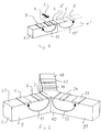
- Fig. 1 shows a known vertical Hall sensor
- the Basic principles are described in US 4,987,467. This Document is hereby used as a reference for the structure of such Sensors included in the present disclosure.
- a semiconductor crystal 1 is the basis for the Hall element or the Hall sensor, this crystal 1 being a cuboid and wherein opposite sides are therefore parallel.
- the reference numerals 2 and 3 are those on the surface of the crystal 1 applied current electrodes referred to. Between these is a first sensor contact 4 arranged, all three contacts and electrodes are strip-shaped and run parallel to one another.
- a so-called vertical described in US 4,987,467 Hall element then also has the dashed line Portion of the crystal 1 'with the first inner current electrode 2 ', the second outer current electrode 3' and a second Sensor contact 5.
- Inside the crystal material 1 is a More conductive connection 13 between the current electrodes 2 and 3 and a more conductive connection 13 'between the current electrodes 2 'and 3' formed.
- FIG. 2 shows a three-armed vertical Hall sensor according to an embodiment of the invention in a view, wherein same features in all figures with the same reference numerals have been designated.
- the only central power electrode 2 is functionally provided for all three arms 9, 29 and 49. Opposite this current electrode 2 are the outer current electrodes 3, 23 and 43 arranged. Between the central electrode 2 and the outer electrodes 3, 23 and 43 are each Sensor contacts or Hall voltage electrodes 4, 24 and 44 arranged.
- the first layer course of the more conductive Layer 13 in the first arm 9 is also the corresponding layer guide 33 shown in the second arm 29.
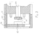
- FIG. 3 now shows a view of a miniature motor inside a housing 50 is arranged.
- the reference symbol 51 is the shaft, which is mounted in a sleeve 52.
- a permanent magnet is on an extension 53 on the shaft 51 54 arranged non-rotatably.
- the permanent magnet 54 is cylindrical and has a hole. Towards him is as little as possible Distance of the vertical multi-arm Hall sensor 60 arranged which can be designed in particular in accordance with FIG. 2 can, the one designated in FIG. 2 by the reference symbol 61 Crystal surface aligned on the permanent magnet 54 is.
- a tubular spacer is advantageously placed on the housing 52 55 placed on the one bearing the sensor 60 Printed circuit board 56 placed and countered with the housing 50 becomes. This makes precise parallel alignment easy accessible from magnet 54 and sensor 60.
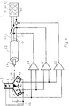
- FIG. 4 is a basic circuit diagram for an electric motor according to the invention.
- the electric motor 62 has over three coils that have leads 63, 64 and 65.
- the shaft that the permanent magnet 60 carries, labeled and opposite her is in a schematic Illustration stylized in a top view of the three-armed vertical Hall sensor arranged.
- the outer current electrodes 3, 23 and 43 are interconnected and via a Power source 66 connected to the inner power electrode 2.
- the three voltage electrodes 4, 24 and 44 are each with the first Inputs of amplifier stages 67, 68 and 69 connected.
- the others Inputs of amplifiers 67, 68 and 69 are each against connected clockwise following voltage electrodes.
- the amplifier stages 67, 68 and 69 are thus with the by 120 ° phase-shifted Hall voltages of the three independent Hall sensors applied in the vertical Hall sensor.
- These three Signals 70, 71 and 72 are shown schematically in element 73.
- These signals are preferably in the amplifiers 67, 68 and 69 appropriately reinforced to go directly to the leads 63, 64 and 65 can be given, so the brushless and preferably miniaturized electric motor 62 without another electrical supply circuit is driven.
- Hall voltages can therefore be amplified as a power signal can be used for an electric motor.
- Element 73 can be an additional external voltage source be, which generates three phase-shifted signals 70, 71 and 72 and for starting and / or for mixing with the signals of the amplifier stages 67, 68 and 69 for the electric motor 62.
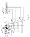
- FIG. 5 is a circuit diagram corresponding to Fig. 4 for a five-armed Hall sensor 100 shown.
- To the central current electrode 2 now five outer current electrodes 103, 113, 123, 133 and 143 added. All external current electrodes are again with the inner current electrode 2 via a current source 66 connected.
- Between the respective pairs of current electrodes 2 and 103, 113, 123, 133 and 143 are Hall voltage electrodes 104, 114, 124, 134 and 144 arranged.
- Analogously to FIG. 4 is then a number of five amplifier stages corresponding to the poor 167, 168, 169, 170 and 171 are provided.
- corresponding leads go from the five amplifiers to the five coil feeders 162, 163, 164, 165 and 166 for the electric motor 62.
- the vertical Hall sensor is a constant current across the Electrodes 2 and 3, 23, ... introduced and the Hall voltage been tapped. This procedure leads to out of phase Output signals that oscillate around 0 volts and thus have essentially no direct voltage component.
- an operation of the described Hall sensors an oscillation at constant voltage and thus variable current the output voltage by a non-zero value from e.g. 3 volts, i.e. with a DC voltage component.
- each output signal of the Hall voltage contacts can also be individually amplified and fed to the motor 62.
- This case not shown in the drawings, leads to a shift in the Hall voltages at different magnetic field strengths, ie that the output voltages at the Zero crossings "of the three-armed sensors at 0 and 180 or 60 and 240 or 120 and 300 degrees at different magnetic field strengths are unequal.
- the Hall sensor according to the invention has in addition to that described Use for driving micromotors further possible applications in all those areas where in different Hall sensors working in a confined space are needed.
- the three- and five-armed vertical Hall sensors is also any other number of sensor arms greater than three possible.
- the sensor itself has the advantage that it is a integrated sensor that is not involved in its manufacture Problems with the parallel and here aligned Alignment of the levels of the contact surfaces, here in the surface 61.
- the contact surfaces themselves are in theirs Alignment and size can be determined very precisely.
- Through integration 2 is the angle of 120 ° or the five-armed sensor shown in Fig. 5 is, the angle of 72 ° between adjacent arms with the highest Accuracy can be generated.
- the Hall sensor has an even number of arms, e.g. six, can in addition to the manner described in connection with the figures from here six in phase separation of 60 degrees Hall voltage sensitivities each opposite Hall sensor arms interconnected to a complete to form a vertical Hall sensor according to FIG. 1.
- each opposite Hall sensor arms interconnected to a complete to form a vertical Hall sensor according to FIG. 1.
- the circuitry is considerably higher.
- the advantage the solution according to FIGS. 2 and 3 is in particular also because that a significantly smaller number of contacts is necessary and a simpler wiring of the sensor is possible.
Abstract
Description
Die Erfindung betrifft einen senkrechten Hallsensor aus einem Halbleiterkristall mit auf der Oberfläche desselben angeordneten Paar von Stromelektroden und mit einem zwischen den Stromelektroden angeordneten Hallspannungskontakt, wobei der Halbleiterkristall eine ausreichende Dicke aufweist, so dass zwischen den Stromelektroden in dem Halbleiterkristall ein Stromfluss ermöglicht wird, der eine Empfindlichkeit des Hallsensors für ein parallel zu der Oberfläche ausgerichtetes Magnetfeld erzeugt.The invention relates to a vertical Hall sensor from a Semiconductor crystal arranged on the surface thereof Pair of current electrodes and with one between the current electrodes arranged Hall voltage contact, the semiconductor crystal has a sufficient thickness so that between the Current electrodes in the semiconductor crystal allows current to flow which is a sensitivity of the Hall sensor for a generated magnetic field aligned parallel to the surface.
Die Erfindung betrifft weiterhin einen bürstenlosen Elektromotor mit mindestens einem Hallsensor und mit einem Permanentmagneten, wobei der Permanentmagnet drehfest mit der Motorwelle verbunden und der Hallsensor diesem Permanentmagneten gegenüber angeordnet ist, wobei der Elektromotor mindestens drei Spulen aufweist.The invention further relates to a brushless electric motor with at least one Hall sensor and with a permanent magnet, the permanent magnet being non-rotatably connected to the motor shaft and the Hall sensor is arranged opposite this permanent magnet is, wherein the electric motor has at least three coils.
Ein senkrechter Hallsensor ist aus der US 4,987,467 bekannt. Senkrechte Hallsensoren sind integrierte Hallsensoren und weisen den Vorteil auf, auf ein Magnetfeld parallel zur Chip-Oberfläche empfindlich zu sein. Solche Hallsensoren werden insbesondere für genaue Messungen von Magnetfeldern eingesetzt.A vertical Hall sensor is known from US 4,987,467. Vertical Hall sensors are integrated Hall sensors and show the advantage of a magnetic field parallel to the chip surface to be sensitive. Such Hall sensors are used in particular for accurate measurements of magnetic fields are used.
Bekannte übliche Hallsensoren werden auch für die Steuerung von Elektromotoren eingesetzt. Ein entsprechender bürstenloser Elektromotor mit der dazugehörigen Steuerung ist aus dem Artikel "Effects of Software Speed-Control Algorithm on Low-Cost Six-Step Brushless DC Drives" von S. Ellerthorpe in Power Conversion-&-Intelligent Motion, Band 22, Nr. 1, Seiten 58 bis 65 (Januar 1996) bekannt.Known common Hall sensors are also used for the control of Electric motors used. A corresponding brushless electric motor with the associated control is from the article "Effects of Software Speed-Control Algorithm on Low-Cost Six-Step Brushless DC Drives "by S. Ellerthorpe in Power Conversion - & - Intelligent Motion, Volume 22, No. 1, pages 58 to 65 (January 1996).
In dem genannten Motor werden drei Hallsensoren, die jeweils 180° einer Kreisscheibe parallel zum Permanentmagneten abdecken, mit einem Versatz von 120° zueinander angeordnet, so dass die von diesen Hallsensoren erzeugten Spannungen ein Drei-Bit-Rückkopplungssignal ergeben, welches die Rotorposition in Bezug auf sechs 60°-Bereiche feststellt. Die diesbezügliche Information wird in IP-, PI- und PPI-Steuerungen zur Erreichung einer konstanten Drehzahl bei dem Elektromotor eingesetzt.In the engine mentioned are three Hall sensors, each Cover 180 ° of a circular disc parallel to the permanent magnet, arranged with an offset of 120 ° to each other so that the voltages generated by these Hall sensors produce a three-bit feedback signal result which is related to the rotor position on six 60 ° ranges. The relevant information is used in IP, PI and PPI controls to achieve a constant speed used in the electric motor.
Dieser Motor weist den Nachteil auf, dass die entsprechenden die Algorithmen der Steuerung ausfuhrenden Systeme einen Raumbedarf haben, der die Möglichkeiten zur Miniaturisierung der Motoren stark einschränkt. Die Anordnung der Hallsensoren ist in Bezug auf die fluchtende Planarität sowie im Hinblick auf die genaue Ausrichtung der Winkel zueinander schwierig.This engine has the disadvantage that the corresponding Algorithms of the systems executing control require a space have the ability to miniaturize the motors severely restricted. The arrangement of the Hall sensors is related on the aligned planarity as well as with regard to the exact Aligning the angles with each other is difficult.
Ausgehend von diesem Stand der Technik liegt der Erfindung die Aufgabe zugrunde, einen senkrechten Hallsensor der eingangs genannten Art so auszubilden, dass mit ihm bessere Winkelauflösungen erreichbar sind, insbesondere dass bei Beaufschlagung mit einem sich drehenden Magnetfeld drei um jeweils 120° verschobene Hall-Spannungen erzeugbar sind.Based on this prior art, the invention lies Task based on a vertical Hall sensor of the aforementioned Type in such a way that with it better angular resolutions are attainable, in particular that when applied with a rotating magnetic field three shifted by 120 ° Hall voltages can be generated.
Weiterhin ist ausgehend von dem genannten Stand der Technik Aufgabe der Erfindung, einen mit einem senkrechten Hallsensor ausgestatteten Elektromotor so auszubilden, dass er als Mikromotor mit möglichst geringem Raumbedarf und einfacher Ansteuerung ausgestaltet werden kann.Furthermore, based on the prior art mentioned, the task is of the invention, one equipped with a vertical Hall sensor Train the electric motor so that it functions as a micromotor designed with the smallest possible space requirement and simple control can be.
Die erste genannte Aufgabe wird erfindungsgemäss für einen senkrechten Hallsensor der eingangs genannten Art dadurch gelöst, dass der Hallsensor über drei oder mehr Armabschnitte verfügt, die in einem gleichmässigen Winkelabstand zueinander angeordnet sind und die in einem zentralen Abschnitt zusammenlaufen, dass jeder Arm über eine äussere Stromelektrode verfügt, der gegenüber im zentralen Abschnitt eine mittlere innere Stromelektrode angeordnet ist, die jeweils das besagte Paar von Stromelektroden bilden, und dass zwischen den jeweiligen äusseren Stromelektroden und der mittleren inneren Stromelektrode ein Hallspannungskontakt angeordnet ist, so dass zwischen den Stromelektroden in jedem Armabschnitt des Halbleiterkristalls ein Stromfluss ermöglicht wird, der für ein parallel zu der Oberfläche ausgerichtetes Magnetfeld mehrere Ausgangssignale des Hallsensors entsprechend der Armanzahl und mit einer entsprechend vorgegebenen Winkelabhängigkeit erzeugt.According to the invention, the first object mentioned is for a vertical one Hall sensor of the type mentioned above solved that the Hall sensor has three or more arm sections, which are arranged at a uniform angular distance from each other are and that converge in a central section that each arm has an outer current electrode, the opposite a central inner current electrode in the central section is arranged, each said pair of current electrodes form, and that between the respective outer current electrodes and a Hall voltage contact in the middle inner current electrode is arranged so that between the current electrodes in each arm section of the semiconductor crystal allows current to flow for a parallel to the surface Magnetic field corresponding to several output signals of the Hall sensor the number of arms and with a corresponding predetermined angle dependency generated.
Dadurch, dass verschiedene Arme jeweils einen vollständigen Hallsensor bilden, kann in sehr genauer Weise eine Empfindlichkeit des Hallsensors für verschiedene Winkel des Magnetfeldes in der Ebene der Kristalloberfläche erreicht werden. Durch die in tegrierte Ausführung ist neben der hervorragenden Genauigkeit der Winkel der Sensoren zueinander durch die gemeinsame Kristalloberfläche auch die Empfindlichkeit für dieselben Anteile des Magnetfeldes gegeben.Because different arms each make a complete Hall sensor form can be a sensitivity in a very accurate manner of the Hall sensor for different angles of the magnetic field in the plane of the crystal surface. By in tegrated execution is in addition to the excellent accuracy the angle of the sensors to each other through the common crystal surface also sensitivity to the same proportions given the magnetic field.
Die weitere Aufgabe wird erfindungsgemäss für einen Elektromotor der eingangs genannten Art dadurch gelöst, dass der Hallsensor ein erfindungsgemässer senkrechter Hallsensor mit mindestens drei Armen ist, dass die Anzahl der Arme der Anzahl der Spulen entspricht, so dass mit dem senkrechten Hallsensor bei drehender Motorwelle mindestens drei mit gleichem Phasenabstand zueinander phasenverschobene Hallspannungen erzeugbar sind, die verstärkt den Spulen als Leistungssignal zuführbar sind.According to the invention, the further object is for an electric motor of the type mentioned in that the Hall sensor a vertical Hall sensor according to the invention with at least three arms is that the number of arms the number of coils corresponds, so that with the vertical Hall sensor when rotating Motor shaft at least three with the same phase distance to each other phase-shifted Hall voltages can be generated, which are amplified the coils can be supplied as a power signal.
Durch die Verwendung des erfindungsgemässen senkrechten Hallsensors bei einem bürstenlosen Elektromotor kann eine sehr einfache Beschaltung desselben erreicht werden, was für die Miniaturisierung der gesamten Einheit sehr vorteilhaft ist.By using the vertical Hall sensor according to the invention A brushless electric motor can be a very simple one Wiring the same can be achieved, what for miniaturization the whole unit is very beneficial.
Weitere vorteilhafte Ausführungsformen sind in den jeweiligen Unteransprüchen gekennzeichnet.Further advantageous embodiments are in the respective Subclaims marked.
Die Erfindung wird nun unter Bezugnahme auf die beigefügten Zeichnungen im Detail an verschiedenen Ausführungsbeispielen der Erfindung beschrieben. Es zeigen:
- Fig. 1
- einen bekannten linearen senkrechten Hallsensor mit einer Weiterbildung hinsichtlich des Signalabgriffs,
- Fig. 2
- eine Ansicht eines dreiarmigen Hallsensors gemäss einem Ausführungsbeispiel der Erfindung,
- Fig. 3
- eine Querschnittsansicht durch einen miniaturisierten Elektromotor mit einem erfindungsgemässen mehrarmigen senkrechten Hallsensor nach Fig. 2,
- Fig. 4
- eine schematische Ansicht eines Schaltbildes zur Ansteuerung des Motors nach Fig. 3 mit dem dreiarmigen senkrechten Hallsensor nach Fig. 2, und
- Fig. 5
- eine schematische Ansicht eines Schaltbildes zur Ansteuerung eines fünf Spulen umfassenden Elektromotors mit einem fünfarmigen senkrechten Hallsensor gemäss einem weiteren Ausführungsbeispiel der Erfindung.
- Fig. 1
- a known linear vertical Hall sensor with a development in terms of signal tapping,
- Fig. 2
- 2 shows a view of a three-armed Hall sensor according to an exemplary embodiment of the invention,
- Fig. 3
- 3 shows a cross-sectional view through a miniaturized electric motor with a multi-armed vertical Hall sensor according to FIG. 2,
- Fig. 4
- a schematic view of a circuit diagram for controlling the motor of FIG. 3 with the three-armed vertical Hall sensor of FIG. 2, and
- Fig. 5
- is a schematic view of a circuit diagram for controlling a five-coil electric motor with a five-armed vertical Hall sensor according to another embodiment of the invention.
Die Fig. 1 zeigt einen bekannten senkrechten Hallsensor, dessen Grundprinzipien in der US 4,987,467 beschrieben sind. Diese Druckschrift wird hiermit als Referenz zum Aufbau eines solchen Sensors in die vorliegende Offenbarung aufgenommen.Fig. 1 shows a known vertical Hall sensor, the Basic principles are described in US 4,987,467. This Document is hereby used as a reference for the structure of such Sensors included in the present disclosure.
Ein Halbleiterkristall 1 ist die Basis für das Hall-Element oder
den Hallsensor, wobei dieser Kristall 1 ein Quader ist und wobei
gegenüberliegende Seiten somit parallel verlaufen. Mit den Bezugszeichen
2 und 3 sind die auf der Oberfläche des Kristalls 1
aufgebrachten Stromelektroden bezeichnet. Zwischen diesen ist
ein erster Sensorkontakt 4 angeordnet, wobei alle drei Kontakte
und Elektroden streifenförmig sind und parallel zueinander verlaufen.
Ein in der US 4,987,467 beschriebenes sogenanntes senkrechtes
Hall-Element verfügt dann zudem über den strichlinierten
Anteil des Kristalls 1' mit der ersten inneren Stromelektrode
2', der zweiten äusseren Stromelektrode 3' sowie einem zweiten
Sensorkontakt 5. Innerhalb des Kristallmaterials 1 wird eine
leitfähigere Verbindung 13 zwischen den Stromelektroden 2 und 3
sowie eine leitfähigere Verbindung 13' zwischen den Stromelektroden
2' und 3' ausgebildet. Damit ergibt sich bei Beaufschlagung
dieses sogenannten senkrechten Hallsensors mit einem entsprechend
dem Pfeil 6 ausgerichteten Magnetfeld eine Hall-Spannung
zwischen den beiden Sensorelektroden 4 und 5, wobei
auch hier die verschiedenen Verbindungsebenen zwischen den Kontaktpunkten
4 und 5 bzw. 2, 2' und 3, 3' sowie dem Magnetfeld 6
jeweils senkrecht verlaufen. Die inneren Stromelektroden 2 und
2' sind einstückig und bilden einen Streifen.A semiconductor crystal 1 is the basis for the Hall element or
the Hall sensor, this crystal 1 being a cuboid and wherein
opposite sides are therefore parallel. With the
Es ist nun möglich, auf den strichlinierten Teil des senkrechten Hallsensors zu verzichten und somit nur mit einer Hälfte zu arbeiten, sofern auf der Rückseite der Sensoren ein zweiter Abgriff für die Hallspannung vorgesehen ist.It is now possible to click on the dashed part of the vertical To dispense with Hall sensors and thus only work with one half, if there is a second tap on the back of the sensors is provided for the Hall voltage.
Die Fig. 2 zeigt einen dreiarmigen senkrechten Hallsensor gemäss
einem Ausführungsbeispiel der Erfindung in einer Ansicht, wobei
gleiche Merkmale in allen Fig. jeweils mit gleichen Bezugszeichen
bezeichnet worden sind. Die einzige zentrale Stromelektrode
2 ist funktional für alle drei Arme 9, 29 und 49 vorgesehen.
Dieser Stromelektrode 2 gegenüber sind die äusseren Stromelektroden
3, 23 und 43 angeordnet. Zwischen der zentralen Elektrode
2 und den äusseren Elektroden 3, 23 bzw. 43 sind jeweils die
Sensorkontakte oder Hallspannungselektroden 4, 24 und 44 angeordnet.
Neben dem ersten Schichtenverlauf der leitfähigeren
Schicht 13 im ersten Arm 9 ist auch die entsprechende Schichtenführung
33 im zweiten Arm 29 dargestellt. 2 shows a three-armed vertical Hall sensor according to
an embodiment of the invention in a view, wherein
same features in all figures with the same reference numerals
have been designated. The only
Es ist entsprechend der US 4,987,467 möglich, diese leitfähige Schicht in einer Vielzahl von Ausgestaltungen vorzunehmen, dies kann insbesondere auch durch das Vorsehen einer gut leitenden, sogenannten beerdigten Schicht ("buried layer") desselben Leitfähigkeitstyps wie dem des den Kristall 1 aufbauenden Halbleiters bestehen.According to US 4,987,467, it is possible to conduct this Layer in a variety of configurations to do this can in particular also be provided by providing a highly conductive, So-called buried layer of the same conductivity type like that of the semiconductor building the crystal 1 consist.
Die Fig. 3 zeigt nun eine Ansicht eines Miniaturmotors, der innerhalb
eines Gehäuses 50 angeordnet ist. Mit dem Bezugszeichen
51 ist die Welle bezeichnet, die in einer Hülse 52 gelagert ist.
Auf der Welle 51 ist auf einem Fortsatz 53 ein Permanentmagnet
54 drehfest angeordnet. Der Permanentmagnet 54 ist zylindrisch
und weist eine Bohrung auf. Ihm gegenüber ist in möglichst geringem
Abstand der senkrechte mehrarmige Hallsensor 60 angeordnet,
der insbesondere entsprechend der Fig. 2 ausgestaltet sein
kann, wobei die in der Fig. 2 mit dem Bezugszeichen 61 bezeichnete
Kristalloberfläche auf den Permanentmagneten 54 ausgerichtet
ist.3 now shows a view of a miniature motor inside
a
Vorteilhafterweise wird auf das Gehäuse 52 ein rohrförmiger Abstandhalter
55 aufgesetzt, auf den eine den Sensor 60 tragende
Leiterplatte 56 aufgesetzt und mit dem Gehäuse 50 gekontert
wird. Dadurch ist in einfacher Weise eine genaue parallele Ausrichtung
von Magnet 54 und Sensor 60 erreichbar.A tubular spacer is advantageously placed on the
Die Beschaltung des Motors nach Fig. 3 ist nun in der Fig. 4
dargestellt, die ein prinzipielles Schaltbild für einen Elektromotor
gemäss der Erfindung zeigt. Der Elektromotor 62 verfügt
über drei Spulen, die Zuleitungen 63, 64 und 65 aufweisen. Mit
dem Bezugszeichen 51 ist wiederum die Welle, die den Permanentmagnet
60 trägt, bezeichnet und ihr gegenüber ist in einer schematischen
Darstellung stilisiert in einer Draufsicht der dreiarmige
senkrechte Hallsensor angeordnet. Die äusseren Stromelektroden
3, 23 und 43 sind zusammengeschaltet und über eine
Stromquelle 66 mit der inneren Stromelektrode 2 verbunden. Die
drei Spannungselektroden 4, 24 und 44 sind jeweils mit ersten
Eingängen von Verstärkerstufen 67, 68 und 69 verbunden. Die weiteren
Eingänge der Verstärker 67, 68 und 69 sind jeweils mit gegen
den Uhrzeigersinn folgenden Spannungselektroden verbunden.
Die Verstärkerstufen 67, 68 und 69 sind somit mit den um jeweils
120° phasenverschobenen Hall-Spannungen der drei unabhängigen
Hallsensoren im senkrechten Hallsensor beaufschlagt. Diese drei
Signale 70, 71 und 72 sind schematisch in dem Element 73 dargestellt.
Vorzugsweise werden diese Signale in den Verstärkern 67,
68 und 69 entsprechend verstärkt, um direkt auf die Zuleitungen
63, 64 und 65 gegeben werden zu können, so dass der bürstenlose
und vorzugsweise miniaturisierte Elektromotor 62 ohne eine weitere
elektrische Versorgungsschaltung angetrieben wird. Die mit
einem erfindungsgemässen mehrarmigen senkrechten Hallsensor erzeugbaren
Hallspannungen können also verstärkt als Leistungssignal
für einen Elektromotor Verwendung finden.The wiring of the motor according to FIG. 3 is now in FIG. 4
shown, which is a basic circuit diagram for an electric motor
according to the invention. The
Das Element 73 kann eine zusätzliche externe Spannungsquelle
sein, die drei phasenverschobenen Signale 70, 71 und 72 erzeugt
und zum Anlaufen und/oder zum Mischen mit den Signalen der Verstärkerstufen
67, 68 und 69 für den Elektromotor 62 bereitstellt.
Neben dem dreiarmigen Hallsensor 80 nach Fig. 4 ist ebenfalls
jede andere mehrarmige Ausgestaltung des Hallsensors möglich. In
der Fig. 5 ist ein Schaltbild entsprechend Fig. 4 für einen fünfarmigen
Hallsensor 100 dargestellt. Zu der zentralen Stromelektrode
2 treten nun fünf äussere Stromelektroden 103, 113,
123, 133 und 143 hinzu. Alle äusseren Stromelektroden sind wiederum
mit der inneren Stromelektrode 2 über eine Stromquelle 66
verbunden. Zwischen den jeweiligen Stromelektrodenpaaren 2 und
103, 113, 123, 133 bzw. 143 sind Hallspannungselektroden 104,
114, 124, 134 und 144 angeordnet. In analoger Weise zur Fig. 4
ist dann eine den Armen entsprechende Anzahl von hier fünf Verstärkerstufen
167, 168, 169, 170 und 171 vorgesehen. Auch hier
gehen von den fünf Verstärkern entsprechende Zuleitungen zu den
fünf Spulenzuführungen 162, 163, 164, 165 und 166 für den Elektromotor
62.In addition to the three-
In den oben beschriebenen Ausführungsbeispielen für den senkrechten
Hallsensor ist jeweils ein konstanter Strom über die
Elektroden 2 und 3, 23, ... eingeleitet und die Hall-Spannung
abgegriffen worden. Diese Vorgehensweise führt zu jeweils phasenverschobenen
Ausgangssignalen, die um 0 Volt oszillieren und
damit im wesentlichen keinen Gleichspannungsanteil aufweisen.
Dagegen wird bei einem Betrieb der beschriebenen Hallsensoren
bei konstanter Spannung und somit variablem Strom eine Oszillation
der Ausgangsspannung um einen von null verschiedenen Wert
von z.B. 3 Volt, d.h. mit einem Gleichspannungsanteil, erreicht.In the above-described embodiments for the vertical
Hall sensor is a constant current across the
Neben der dargestellten Möglichkeit der Differenzbildung in den
Verstärkerstufen 67 bzw. 167 und folgenden, kann jedes Ausgangssignal
der Hallspannungskontakte auch individuell verstärkt und
dem Motor 62 zugeführt werden. Dieser in den Zeichnungen nicht
dargestellte Fall führt zu einer Verschiebung der Hallspannungen
bei verschiedenen Magnetfeldstärken, d.h. dass die Ausgangsspannungen
bei den ![]()
![]()
Der erfindungsgemässe Hallsensor weist neben dem beschriebenen Einsatz für den Antrieb von Mikromotoren weitere Anwendungsmöglichkeiten in all denjenigen Bereichen auf, in denen in verschiedenen Orientierungen arbeitende Hallsensoren auf engem Raum benötigt werden. Neben den dargestellten drei- und fünfarmigen senkrechten Hallsensoren ist auch jede andere Zahl von Sensorarmen grösser als drei möglich.The Hall sensor according to the invention has in addition to that described Use for driving micromotors further possible applications in all those areas where in different Hall sensors working in a confined space are needed. In addition to the three- and five-armed vertical Hall sensors is also any other number of sensor arms greater than three possible.
Der Sensor an sich weist den Vorteil auf, dass es sich um einen
integrierten Sensor handelt, der bei seiner Herstellung keinerlei
Probleme hinsichtlich der parallelen und hier fluchtenden
Ausrichtung der Ebenen der Kontaktflächen, hier in der Oberfläche
61, aufweist. Auch die Kontaktflächen selber sind in ihrer
Ausrichtung und Grösse sehr genau vorbestimmbar. Durch die Integration
ist beim dreiarmigen Sensor nach Fig. 2 der Winkel von
120° bzw. beim fünfarmigen Sensor, der in Fig. 5 dargestellt
ist, der Winkel von 72° zwischen benachbarten Armen mit höchster
Genauigkeit erzeugbar.The sensor itself has the advantage that it is a
integrated sensor that is not involved in its manufacture
Problems with the parallel and here aligned
Alignment of the levels of the contact surfaces, here in the
Bei einer geradzahligen Armzahl des Hallsensors, z.B. sechs, können neben der im Zusammenhang mit den Fig. beschriebenen Weise von dann hier sechs im Phasenabstand von 60 Grad liegenden Hallspannungsempfindlichkeiten jeweils gegenüberliegende Hallsensorarme zusammengeschaltet werden, um einen vollständigen senkrechten Hallsensor nach Fig. 1 zu bilden. In dem in diesem Abschnitt gewählten Beispiel von sechs Armen ergeben sich dann drei Hallspannungsempfindlichkeiten im Phasenabstand von 120 Grad zueinander wie bei dem dreiarmigen Hallsensor nach Fig 2. Der Schaltungsaufwand ist jedoch erheblich höher. Der Vorteil der Lösung nach den Fig. 2 und 3 liegt insbesondere auch daran, dass eine erheblich geringere Anzahl von Kontakten notwendig und eine einfachere Beschaltung des Sensors möglich ist.If the Hall sensor has an even number of arms, e.g. six, can in addition to the manner described in connection with the figures from here six in phase separation of 60 degrees Hall voltage sensitivities each opposite Hall sensor arms interconnected to a complete to form a vertical Hall sensor according to FIG. 1. In that in this Section chosen example of six arms then result three Hall voltage sensitivities with a phase separation of 120 Degrees to each other as in the three-armed Hall sensor according to FIG. 2. However, the circuitry is considerably higher. The advantage the solution according to FIGS. 2 and 3 is in particular also because that a significantly smaller number of contacts is necessary and a simpler wiring of the sensor is possible.
Claims (9)
Priority Applications (10)
| Application Number | Priority Date | Filing Date | Title |
|---|---|---|---|
| EP98810370A EP0954085A1 (en) | 1998-04-27 | 1998-04-27 | Vertical hall sensor and brushless electric motor with a vertical hall sensor |
| KR1020007011968A KR20010043086A (en) | 1998-04-27 | 1999-04-19 | Vertical hall effect sensor and brushless electric motor with a vertical hall effect sensor |
| AT99913053T ATE250295T1 (en) | 1998-04-27 | 1999-04-19 | VERTICAL HALL SENSOR AND BRUSHLESS ELECTRIC MOTOR WITH A VERTICAL HALL SENSOR |
| CA002327467A CA2327467A1 (en) | 1998-04-27 | 1999-04-19 | Vertical hall effect sensor and brushless electric motor with a vertical hall effect sensor |
| PCT/CH1999/000156 WO1999056381A1 (en) | 1998-04-27 | 1999-04-19 | Vertical hall effect sensor and brushless electric motor with a vertical hall effect sensor |
| AU31354/99A AU744453B2 (en) | 1998-04-27 | 1999-04-19 | Vertical hall effect sensor and brushless electric motor with a vertical hall effect sensor |
| JP2000546445A JP2002513270A (en) | 1998-04-27 | 1999-04-19 | Vertical Hall effect sensor and brushless electric motor with vertical Hall effect sensor |
| DE59907022T DE59907022D1 (en) | 1998-04-27 | 1999-04-19 | VERTICAL HALL SENSOR AND BRUSHLESS ELECTRIC MOTOR WITH A VERTICAL HALL SENSOR |
| US09/674,123 US6542068B1 (en) | 1998-04-27 | 1999-04-19 | Vertical hall effect sensor and a brushless electric motor having a vertical hall effect sensor |
| EP99913053A EP1076924B1 (en) | 1998-04-27 | 1999-04-19 | Vertical hall effect sensor and brushless electric motor with a vertical hall effect sensor |
Applications Claiming Priority (1)
| Application Number | Priority Date | Filing Date | Title |
|---|---|---|---|
| EP98810370A EP0954085A1 (en) | 1998-04-27 | 1998-04-27 | Vertical hall sensor and brushless electric motor with a vertical hall sensor |
Publications (1)
| Publication Number | Publication Date |
|---|---|
| EP0954085A1 true EP0954085A1 (en) | 1999-11-03 |
Family
ID=8236055
Family Applications (2)
| Application Number | Title | Priority Date | Filing Date |
|---|---|---|---|
| EP98810370A Withdrawn EP0954085A1 (en) | 1998-04-27 | 1998-04-27 | Vertical hall sensor and brushless electric motor with a vertical hall sensor |
| EP99913053A Expired - Lifetime EP1076924B1 (en) | 1998-04-27 | 1999-04-19 | Vertical hall effect sensor and brushless electric motor with a vertical hall effect sensor |
Family Applications After (1)
| Application Number | Title | Priority Date | Filing Date |
|---|---|---|---|
| EP99913053A Expired - Lifetime EP1076924B1 (en) | 1998-04-27 | 1999-04-19 | Vertical hall effect sensor and brushless electric motor with a vertical hall effect sensor |
Country Status (9)
| Country | Link |
|---|---|
| US (1) | US6542068B1 (en) |
| EP (2) | EP0954085A1 (en) |
| JP (1) | JP2002513270A (en) |
| KR (1) | KR20010043086A (en) |
| AT (1) | ATE250295T1 (en) |
| AU (1) | AU744453B2 (en) |
| CA (1) | CA2327467A1 (en) |
| DE (1) | DE59907022D1 (en) |
| WO (1) | WO1999056381A1 (en) |
Cited By (10)
| Publication number | Priority date | Publication date | Assignee | Title |
|---|---|---|---|---|
| US6545462B2 (en) | 2000-08-21 | 2003-04-08 | Sentron Ag | Sensor for the detection of the direction of a magnetic field having magnetic flux concentrators and hall elements |
| DE10150955C1 (en) * | 2001-10-16 | 2003-06-12 | Fraunhofer Ges Forschung | Vertical Hall sensor |
| DE10150950C1 (en) * | 2001-10-16 | 2003-06-18 | Fraunhofer Ges Forschung | Compact vertical Hall sensor |
| WO2006028426A1 (en) * | 2004-09-08 | 2006-03-16 | Inessa Antonovna Bolshakova | Magnetic field measuring sensor |
| WO2008145662A1 (en) * | 2007-05-29 | 2008-12-04 | Ecole Polytechnique Federale De Lausanne | Magnetic field sensor for measuring direction of a magnetic field in a plane |
| EP2192417A3 (en) * | 2008-11-28 | 2010-11-17 | Melexis Tessenderlo NV | Vertical hall sensor |
| US8624587B2 (en) | 2008-04-08 | 2014-01-07 | Senis Ag | Magnetic field sensor measuring a direction of a magnetic field in a plane and current sensor |
| DE102014007208B3 (en) * | 2014-05-19 | 2015-04-23 | Micronas Gmbh | Hall sensor with several Hall elements |
| DE102014010547A1 (en) | 2014-07-14 | 2016-01-14 | Albert-Ludwigs-Universität Freiburg | Hall sensor |
| DE102015001064A1 (en) | 2015-01-30 | 2016-08-04 | Micronas Gmbh | A method for waking up a magnetic field sensor device and a magnetic field sensor device |
Families Citing this family (57)
| Publication number | Priority date | Publication date | Assignee | Title |
|---|---|---|---|---|
| CN1716736A (en) * | 2004-06-29 | 2006-01-04 | 许晓华 | Brushless DC motor with external Hall element |
| EP1772737A3 (en) * | 2005-10-08 | 2008-02-20 | Melexis Technologies SA | Assembly group for the current measurement |
| DE102005060350B4 (en) | 2005-12-16 | 2014-07-10 | Continental Automotive Gmbh | Method for controlling a combustion process of a supercharged internal combustion engine with exhaust gas recirculation |
| US7847536B2 (en) * | 2006-08-31 | 2010-12-07 | Itron, Inc. | Hall sensor with temperature drift control |
| JP2008086117A (en) * | 2006-09-27 | 2008-04-10 | Aisin Seiki Co Ltd | Electric fluid pump |
| JP5401902B2 (en) * | 2008-10-03 | 2014-01-29 | 日本電産株式会社 | motor |
| EP2234185B1 (en) * | 2009-03-24 | 2012-10-10 | austriamicrosystems AG | Vertical Hall sensor and method of producing a vertical Hall sensor |
| US9062990B2 (en) | 2011-02-25 | 2015-06-23 | Allegro Microsystems, Llc | Circular vertical hall magnetic field sensing element and method with a plurality of continuous output signals |
| US8786279B2 (en) | 2011-02-25 | 2014-07-22 | Allegro Microsystems, Llc | Circuit and method for processing signals generated by a plurality of sensors |
| US8729890B2 (en) | 2011-04-12 | 2014-05-20 | Allegro Microsystems, Llc | Magnetic angle and rotation speed sensor with continuous and discontinuous modes of operation based on rotation speed of a target object |
| US8860410B2 (en) | 2011-05-23 | 2014-10-14 | Allegro Microsystems, Llc | Circuits and methods for processing a signal generated by a plurality of measuring devices |
| US8890518B2 (en) | 2011-06-08 | 2014-11-18 | Allegro Microsystems, Llc | Arrangements for self-testing a circular vertical hall (CVH) sensing element and/or for self-testing a magnetic field sensor that uses a circular vertical hall (CVH) sensing element |
| US8988072B2 (en) | 2011-07-21 | 2015-03-24 | Infineon Technologies Ag | Vertical hall sensor with high electrical symmetry |
| US9007060B2 (en) | 2011-07-21 | 2015-04-14 | Infineon Technologies Ag | Electronic device with ring-connected hall effect regions |
| US8793085B2 (en) | 2011-08-19 | 2014-07-29 | Allegro Microsystems, Llc | Circuits and methods for automatically adjusting a magnetic field sensor in accordance with a speed of rotation sensed by the magnetic field sensor |
| US8922206B2 (en) | 2011-09-07 | 2014-12-30 | Allegro Microsystems, Llc | Magnetic field sensing element combining a circular vertical hall magnetic field sensing element with a planar hall element |
| US9285438B2 (en) | 2011-09-28 | 2016-03-15 | Allegro Microsystems, Llc | Circuits and methods for processing signals generated by a plurality of magnetic field sensing elements |
| US9046383B2 (en) | 2012-01-09 | 2015-06-02 | Allegro Microsystems, Llc | Systems and methods that use magnetic field sensors to identify positions of a gear shift lever |
| US9312472B2 (en) | 2012-02-20 | 2016-04-12 | Infineon Technologies Ag | Vertical hall device with electrical 180 degree symmetry |
| US9182456B2 (en) | 2012-03-06 | 2015-11-10 | Allegro Microsystems, Llc | Magnetic field sensor for sensing rotation of an object |
| US10215550B2 (en) | 2012-05-01 | 2019-02-26 | Allegro Microsystems, Llc | Methods and apparatus for magnetic sensors having highly uniform magnetic fields |
| US10821591B2 (en) | 2012-11-13 | 2020-11-03 | Milwaukee Electric Tool Corporation | High-power cordless, hand-held power tool including a brushless direct current motor |
| US8749005B1 (en) | 2012-12-21 | 2014-06-10 | Allegro Microsystems, Llc | Magnetic field sensor and method of fabricating a magnetic field sensor having a plurality of vertical hall elements arranged in at least a portion of a polygonal shape |
| US9606190B2 (en) | 2012-12-21 | 2017-03-28 | Allegro Microsystems, Llc | Magnetic field sensor arrangements and associated methods |
| US9417295B2 (en) | 2012-12-21 | 2016-08-16 | Allegro Microsystems, Llc | Circuits and methods for processing signals generated by a circular vertical hall (CVH) sensing element in the presence of a multi-pole magnet |
| US9548443B2 (en) | 2013-01-29 | 2017-01-17 | Allegro Microsystems, Llc | Vertical Hall Effect element with improved sensitivity |
| US9377285B2 (en) | 2013-02-13 | 2016-06-28 | Allegro Microsystems, Llc | Magnetic field sensor and related techniques that provide varying current spinning phase sequences of a magnetic field sensing element |
| US9389060B2 (en) | 2013-02-13 | 2016-07-12 | Allegro Microsystems, Llc | Magnetic field sensor and related techniques that provide an angle error correction module |
| US9362485B2 (en) | 2013-03-14 | 2016-06-07 | Robert Bosch Gmbh | Vertical hall effect sensor with offset reduction using depletion regions |
| US9099638B2 (en) | 2013-03-15 | 2015-08-04 | Allegro Microsystems, Llc | Vertical hall effect element with structures to improve sensitivity |
| US9400164B2 (en) | 2013-07-22 | 2016-07-26 | Allegro Microsystems, Llc | Magnetic field sensor and related techniques that provide an angle correction module |
| US9312473B2 (en) | 2013-09-30 | 2016-04-12 | Allegro Microsystems, Llc | Vertical hall effect sensor |
| US9574867B2 (en) | 2013-12-23 | 2017-02-21 | Allegro Microsystems, Llc | Magnetic field sensor and related techniques that inject an error correction signal into a signal channel to result in reduced error |
| US10120042B2 (en) | 2013-12-23 | 2018-11-06 | Allegro Microsystems, Llc | Magnetic field sensor and related techniques that inject a synthesized error correction signal into a signal channel to result in reduced error |
| US9547048B2 (en) * | 2014-01-14 | 2017-01-17 | Allegro Micosystems, LLC | Circuit and method for reducing an offset component of a plurality of vertical hall elements arranged in a circle |
| US9753097B2 (en) | 2014-05-05 | 2017-09-05 | Allegro Microsystems, Llc | Magnetic field sensors and associated methods with reduced offset and improved accuracy |
| JP6209486B2 (en) * | 2014-05-13 | 2017-10-04 | 双葉電子工業株式会社 | Angle detection device and servo device using the angle detection device |
| US9448288B2 (en) | 2014-05-20 | 2016-09-20 | Allegro Microsystems, Llc | Magnetic field sensor with improved accuracy resulting from a digital potentiometer |
| DE102014110974A1 (en) | 2014-08-01 | 2016-02-04 | Micronas Gmbh | Method for suppressing stray field influences of current-carrying conductors on systems for measuring angles by means of X / Y Hall sensors and permanent magnets |
| US9823092B2 (en) | 2014-10-31 | 2017-11-21 | Allegro Microsystems, Llc | Magnetic field sensor providing a movement detector |
| US9638766B2 (en) | 2014-11-24 | 2017-05-02 | Allegro Microsystems, Llc | Magnetic field sensor with improved accuracy resulting from a variable potentiometer and a gain circuit |
| US9684042B2 (en) | 2015-02-27 | 2017-06-20 | Allegro Microsystems, Llc | Magnetic field sensor with improved accuracy and method of obtaining improved accuracy with a magnetic field sensor |
| US11163022B2 (en) | 2015-06-12 | 2021-11-02 | Allegro Microsystems, Llc | Magnetic field sensor for angle detection with a phase-locked loop |
| US9739848B1 (en) | 2016-02-01 | 2017-08-22 | Allegro Microsystems, Llc | Circular vertical hall (CVH) sensing element with sliding integration |
| US10481220B2 (en) | 2016-02-01 | 2019-11-19 | Allegro Microsystems, Llc | Circular vertical hall (CVH) sensing element with signal processing and arctangent function |
| US9739847B1 (en) | 2016-02-01 | 2017-08-22 | Allegro Microsystems, Llc | Circular vertical hall (CVH) sensing element with signal processing |
| US10385964B2 (en) | 2016-06-08 | 2019-08-20 | Allegro Microsystems, Llc | Enhanced neutral gear sensor |
| US10585147B2 (en) | 2016-06-14 | 2020-03-10 | Allegro Microsystems, Llc | Magnetic field sensor having error correction |
| US10739164B2 (en) | 2017-01-27 | 2020-08-11 | Allegro Microsystems, Llc | Circuit for detecting motion of an object |
| US10495701B2 (en) | 2017-03-02 | 2019-12-03 | Allegro Microsystems, Llc | Circular vertical hall (CVH) sensing element with DC offset removal |
| JP7141825B2 (en) * | 2017-12-28 | 2022-09-26 | 旭化成エレクトロニクス株式会社 | magnetic sensor |
| US10823586B2 (en) | 2018-12-26 | 2020-11-03 | Allegro Microsystems, Llc | Magnetic field sensor having unequally spaced magnetic field sensing elements |
| JP7249865B2 (en) * | 2019-05-08 | 2023-03-31 | 旭化成エレクトロニクス株式会社 | Magnetic sensor and magnetic sensor module |
| US11237020B2 (en) | 2019-11-14 | 2022-02-01 | Allegro Microsystems, Llc | Magnetic field sensor having two rows of magnetic field sensing elements for measuring an angle of rotation of a magnet |
| US11280637B2 (en) | 2019-11-14 | 2022-03-22 | Allegro Microsystems, Llc | High performance magnetic angle sensor |
| US11802922B2 (en) | 2021-01-13 | 2023-10-31 | Allegro Microsystems, Llc | Circuit for reducing an offset component of a plurality of vertical hall elements arranged in one or more circles |
| US11473935B1 (en) | 2021-04-16 | 2022-10-18 | Allegro Microsystems, Llc | System and related techniques that provide an angle sensor for sensing an angle of rotation of a ferromagnetic screw |
Citations (1)
| Publication number | Priority date | Publication date | Assignee | Title |
|---|---|---|---|---|
| US3988654A (en) * | 1973-12-21 | 1976-10-26 | Hitachi, Ltd. | Miniature brushless motor |
Family Cites Families (9)
| Publication number | Priority date | Publication date | Assignee | Title |
|---|---|---|---|---|
| US3202913A (en) * | 1961-05-29 | 1965-08-24 | Ibm | High sensitivity hall effect probe |
| JPS5220317B2 (en) * | 1974-12-25 | 1977-06-02 | ||
| JPS5884478A (en) * | 1981-11-13 | 1983-05-20 | Nec Corp | Metal oxide semiconductor type magnetoresistance effect element |
| JPS59117182A (en) * | 1982-12-23 | 1984-07-06 | Toshiba Corp | Manufacture of hall element |
| CH662905A5 (en) | 1983-12-19 | 1987-10-30 | Landis & Gyr Ag | INTEGRATED HALL ELEMENT. |
| JPS60154582A (en) * | 1984-01-23 | 1985-08-14 | Nec Corp | Hall element |
| JP2522214B2 (en) * | 1989-10-05 | 1996-08-07 | 日本電装株式会社 | Semiconductor device and manufacturing method thereof |
| US5119166A (en) * | 1990-02-06 | 1992-06-02 | Honeywell Inc. | Hall effect element aligned to reduce package-induced offsets |
| US5173758A (en) * | 1991-10-28 | 1992-12-22 | General Motors Corporation | Hall generator with four arms |
-
1998
- 1998-04-27 EP EP98810370A patent/EP0954085A1/en not_active Withdrawn
-
1999
- 1999-04-19 DE DE59907022T patent/DE59907022D1/en not_active Expired - Fee Related
- 1999-04-19 AT AT99913053T patent/ATE250295T1/en not_active IP Right Cessation
- 1999-04-19 US US09/674,123 patent/US6542068B1/en not_active Expired - Fee Related
- 1999-04-19 AU AU31354/99A patent/AU744453B2/en not_active Ceased
- 1999-04-19 EP EP99913053A patent/EP1076924B1/en not_active Expired - Lifetime
- 1999-04-19 JP JP2000546445A patent/JP2002513270A/en active Pending
- 1999-04-19 KR KR1020007011968A patent/KR20010043086A/en not_active Application Discontinuation
- 1999-04-19 WO PCT/CH1999/000156 patent/WO1999056381A1/en not_active Application Discontinuation
- 1999-04-19 CA CA002327467A patent/CA2327467A1/en not_active Abandoned
Patent Citations (1)
| Publication number | Priority date | Publication date | Assignee | Title |
|---|---|---|---|---|
| US3988654A (en) * | 1973-12-21 | 1976-10-26 | Hitachi, Ltd. | Miniature brushless motor |
Non-Patent Citations (3)
| Title |
|---|
| NAKAMURA T ET AL: "INTEGRATED MAGNETIC SENSORS", SENSORS AND ACTUATORS A, vol. A22, no. 1 / 03, 1 March 1990 (1990-03-01), pages 762 - 769, XP000358528 * |
| PARANJAPE M ET AL: "A CMOS-COMPATIBLE 2-D VERTICAL HALL MAGNETIC-FIELD SENSOR USING ACTIVE CARRIER CONFINEMENT AND POST-PROCESS MICROMACHINING", SENSORS AND ACTUATORS A, vol. A53, no. 1/03, May 1996 (1996-05-01), pages 278 - 282, XP000620310 * |
| ROUMENIN CH S: "PARALLEL-FIELD HALL MICROSENSORS: AN OVERVIEW", SENSORS AND ACTUATORS A, vol. A30, no. 1 / 02, 1 January 1992 (1992-01-01), pages 77 - 87, XP000277696 * |
Cited By (18)
| Publication number | Priority date | Publication date | Assignee | Title |
|---|---|---|---|---|
| US6545462B2 (en) | 2000-08-21 | 2003-04-08 | Sentron Ag | Sensor for the detection of the direction of a magnetic field having magnetic flux concentrators and hall elements |
| KR100810784B1 (en) * | 2000-08-21 | 2008-03-06 | 멜렉시스 테크놀로기스 에스에이 | Sensor for the detection of the direction of a magnetic field |
| DE10150955C1 (en) * | 2001-10-16 | 2003-06-12 | Fraunhofer Ges Forschung | Vertical Hall sensor |
| DE10150950C1 (en) * | 2001-10-16 | 2003-06-18 | Fraunhofer Ges Forschung | Compact vertical Hall sensor |
| WO2006028426A1 (en) * | 2004-09-08 | 2006-03-16 | Inessa Antonovna Bolshakova | Magnetic field measuring sensor |
| WO2008145662A1 (en) * | 2007-05-29 | 2008-12-04 | Ecole Polytechnique Federale De Lausanne | Magnetic field sensor for measuring direction of a magnetic field in a plane |
| EP2000813A1 (en) * | 2007-05-29 | 2008-12-10 | Ecole Polytechnique Fédérale de Lausanne | Magnetic field sensor for measuring a direction of a magnetic field in a plane |
| US8624587B2 (en) | 2008-04-08 | 2014-01-07 | Senis Ag | Magnetic field sensor measuring a direction of a magnetic field in a plane and current sensor |
| US8164149B2 (en) | 2008-11-28 | 2012-04-24 | Melexis Technologies Sa | Vertical hall sensor |
| EP2192417A3 (en) * | 2008-11-28 | 2010-11-17 | Melexis Tessenderlo NV | Vertical hall sensor |
| CN101750591B (en) * | 2008-11-28 | 2014-07-23 | 迈来芯科技有限公司 | Vertical hall sensor |
| DE102014007208B3 (en) * | 2014-05-19 | 2015-04-23 | Micronas Gmbh | Hall sensor with several Hall elements |
| US9851419B2 (en) | 2014-05-19 | 2017-12-26 | Tdk-Micronas Gmbh | Hall sensor |
| DE102014010547A1 (en) | 2014-07-14 | 2016-01-14 | Albert-Ludwigs-Universität Freiburg | Hall sensor |
| US9709639B2 (en) | 2014-07-14 | 2017-07-18 | Tdk-Micronas Gmbh | Hall effect sensor |
| DE102014010547B4 (en) | 2014-07-14 | 2023-06-07 | Albert-Ludwigs-Universität Freiburg | Hall sensor |
| DE102015001064A1 (en) | 2015-01-30 | 2016-08-04 | Micronas Gmbh | A method for waking up a magnetic field sensor device and a magnetic field sensor device |
| DE102015001064B4 (en) * | 2015-01-30 | 2021-04-08 | Tdk-Micronas Gmbh | Method for waking up a magnetic field sensor device and a magnetic field sensor device |
Also Published As
| Publication number | Publication date |
|---|---|
| WO1999056381A1 (en) | 1999-11-04 |
| CA2327467A1 (en) | 1999-11-04 |
| EP1076924A1 (en) | 2001-02-21 |
| AU3135499A (en) | 1999-11-16 |
| AU744453B2 (en) | 2002-02-21 |
| US6542068B1 (en) | 2003-04-01 |
| ATE250295T1 (en) | 2003-10-15 |
| KR20010043086A (en) | 2001-05-25 |
| JP2002513270A (en) | 2002-05-08 |
| DE59907022D1 (en) | 2003-10-23 |
| EP1076924B1 (en) | 2003-09-17 |
Similar Documents
| Publication | Publication Date | Title |
|---|---|---|
| EP1076924B1 (en) | Vertical hall effect sensor and brushless electric motor with a vertical hall effect sensor | |
| DE10150955C1 (en) | Vertical Hall sensor | |
| DE60218935T2 (en) | Rotating electrical machine with three-phase ring coils and permanent magnets | |
| DE19634281C2 (en) | Measuring device for contactless detection of an angle of rotation or a linear movement | |
| DE102007039050B4 (en) | Linear segment or revolution counter with a ferromagnetic element | |
| DE60200499T2 (en) | Position sensor, especially for detecting the rotation of a steering column | |
| DE2900541B2 (en) | Control signal generator for the commutation device of an electronically commutated DC motor | |
| EP0147610B1 (en) | Wave guide switch | |
| EP1436849A2 (en) | Compact vertical hall sensor | |
| DE2937866B2 (en) | Brushless DC motor | |
| EP2037286A1 (en) | Measuring device for measuring a magnetic field | |
| DE3540349A1 (en) | LINEAR FUNCTION TURN DETECTOR | |
| DE60215176T2 (en) | POLYPHASENMOTOR | |
| DE3013249C2 (en) | ||
| EP0418712B1 (en) | Position sensor | |
| DE2618293C2 (en) | ||
| EP0150070A2 (en) | Commutatorless direct-current motor with a ironless stator winding | |
| DE69820982T2 (en) | Multipole magnetic ring | |
| DE4215641C2 (en) | Sensor or encoder for rotary positions or movements | |
| DE2900547C2 (en) | Control signal generator for the commutation device of a brushless electronic motor | |
| DE2309226A1 (en) | ANGLE POSITION CONVERTER | |
| DE102016201759B4 (en) | Method for measuring the magnetic field and for moving a body in a magnetic field and its use as a magnetic field sensor and as an electric motor | |
| DE19527981A1 (en) | Electronically commutated electric motor, such as switched reluctance (SR) drive motor for motor vehicles, washing machines, lawn mowers etc - has magnetic field sensitive element for each phase of motor arranged at small distance from pole wheels | |
| DE2006487C3 (en) | Tachometric negative feedback arrangement for a brushless direct current motor | |
| DE10201295A1 (en) | Turning angle detector |
Legal Events
| Date | Code | Title | Description |
|---|---|---|---|
| PUAI | Public reference made under article 153(3) epc to a published international application that has entered the european phase |
Free format text: ORIGINAL CODE: 0009012 |
|
| AK | Designated contracting states |
Kind code of ref document: A1 Designated state(s): AT BE CH CY DE DK ES FI FR GB GR IE IT LI LU MC NL PT SE |
|
| AX | Request for extension of the european patent |
Free format text: AL;LT;LV;MK;RO;SI |
|
| AKX | Designation fees paid | ||
| REG | Reference to a national code |
Ref country code: DE Ref legal event code: 8566 |
|
| STAA | Information on the status of an ep patent application or granted ep patent |
Free format text: STATUS: THE APPLICATION IS DEEMED TO BE WITHDRAWN |
|
| 18D | Application deemed to be withdrawn |
Effective date: 20000504 |