EP0954002A2 - Thermal magnetic circuit breakers - Google Patents
Thermal magnetic circuit breakers Download PDFInfo
- Publication number
- EP0954002A2 EP0954002A2 EP99303234A EP99303234A EP0954002A2 EP 0954002 A2 EP0954002 A2 EP 0954002A2 EP 99303234 A EP99303234 A EP 99303234A EP 99303234 A EP99303234 A EP 99303234A EP 0954002 A2 EP0954002 A2 EP 0954002A2
- Authority
- EP
- European Patent Office
- Prior art keywords
- trip
- ratchet
- lever
- circuit breaker
- housing
- Prior art date
- Legal status (The legal status is an assumption and is not a legal conclusion. Google has not performed a legal analysis and makes no representation as to the accuracy of the status listed.)
- Granted
Links
Images


Classifications
-
- H—ELECTRICITY
- H01—ELECTRIC ELEMENTS
- H01H—ELECTRIC SWITCHES; RELAYS; SELECTORS; EMERGENCY PROTECTIVE DEVICES
- H01H71/00—Details of the protective switches or relays covered by groups H01H73/00 - H01H83/00
- H01H71/04—Means for indicating condition of the switching device
-
- H—ELECTRICITY
- H01—ELECTRIC ELEMENTS
- H01H—ELECTRIC SWITCHES; RELAYS; SELECTORS; EMERGENCY PROTECTIVE DEVICES
- H01H71/00—Details of the protective switches or relays covered by groups H01H73/00 - H01H83/00
- H01H71/04—Means for indicating condition of the switching device
- H01H2071/042—Means for indicating condition of the switching device with different indications for different conditions, e.g. contact position, overload, short circuit or earth leakage
-
- H—ELECTRICITY
- H01—ELECTRIC ELEMENTS
- H01H—ELECTRIC SWITCHES; RELAYS; SELECTORS; EMERGENCY PROTECTIVE DEVICES
- H01H71/00—Details of the protective switches or relays covered by groups H01H73/00 - H01H83/00
- H01H71/10—Operating or release mechanisms
- H01H71/12—Automatic release mechanisms with or without manual release
- H01H71/14—Electrothermal mechanisms
- H01H71/16—Electrothermal mechanisms with bimetal element
- H01H71/164—Heating elements
-
- H—ELECTRICITY
- H01—ELECTRIC ELEMENTS
- H01H—ELECTRIC SWITCHES; RELAYS; SELECTORS; EMERGENCY PROTECTIVE DEVICES
- H01H71/00—Details of the protective switches or relays covered by groups H01H73/00 - H01H83/00
- H01H71/10—Operating or release mechanisms
- H01H71/12—Automatic release mechanisms with or without manual release
- H01H71/24—Electromagnetic mechanisms
- H01H71/2472—Electromagnetic mechanisms with rotatable armatures
Definitions
- the invention relates to a thermomagnetic circuit breaker having a selective trip display.
- thermomagnetic circuit breaker A means for providing a visual display of an overload condition (reason for trip) in a thermomagnetic circuit breaker is disclosed in US 3,883,781 and US 5,519,561.
- the systems described therein use either mechanical or electrical logic information, provided by the bimetallic strip, to execute and produce a display of the overload condition. If such a device is equipped only with overload and momentary reaction elements (trip elements), a selective trip display is provided, where an instantaneous trip reaction exists when the operating handle designates the "tripped" state and the overload display system is not activated.
- Printed source US 5,485,343 describes an electronic trip unit for a circuit breaker which permits the user to determine the intensity of as well as the reason for the overcurrent condition after occurrence of the overcurrent trip.
- the electronic trip display for such trip information is similar to the display described in US 4,870,531, and the control unit for such an electronic trip unit is like the trip unit described in US 4,672,501.
- circuit breakers having electronic trip units such as US 4,870,631
- thermomagnetic circuit breaker so that upon trip of the thermomagnetic circuit breaker the reason for trip is displayed in simple fashion.
- the thermomagnetic circuit breaker has a display means that selectively reports the reason for trip.
- Two tripping bars operable independently of one another, comprise the trip function as well as the display means.
- a first tripping bar cooperates with the overload reaction element to execute and display the overload trip.
- a second tripping bar cooperates with the momentary reaction element to produce and display the momentary trip.
- the two tripping bars cooperate with the ground leak reaction element to produce and display the ground leak trip.
- the operating handle goes into a tripped position.
- neither of the tripping bars cooperates with the accessory trip element, so that the operating handle represents the only means for display of the trip.
- thermomagnetic circuit breaker is made possible.
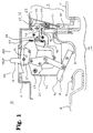
- a circuit breaker 10 arranged in a preformed housing is shown in Fig. 1 and consists of a housing 11, an operating mechanism 12, a control element (operating grip, handle) 13, a current path 14 and a trip unit 15.
- a line connection 16 and a load connection 17 of the current path 14 are connected with a protective circuit (not shown) via fastening elements (not shown).
- a movable contact 18 of a movable contact arm 20 lies on a stationary contact 19 of the line connection 16 to produce an electric current flow in the current path 14 through the line connection 16, the stationary contact 19, the movable contact 18, the movable contact arm 20, a flexible line 21 and the load connection 17.
- the operating mechanism 12 works in a fashion similar to that disclosed in US 3,158,717 and serves to open and close the movable contact arm 20.
- a mechanical supporting member 22 in the housing 11 forms a rotary bearing 23 at one end of a ratchet lever 24.
- a ratchet lever surface 25 at the other end of the ratchet lever 24 opposite the bearing 23 is connected with a ratchet surface 26 of a first ratchet 27, which is seated rotary in the mechanical supporting member 22.
- a second ratchet 29, which is seated rotary on a rotating shaft 30 in the mechanical supporting member 22, comprises a ratchet finger 31, which cooperates with a supporting surface 32 on the first ratchet 27.
- the trip unit 15 consists of a momentary reaction element 40, a thermal reaction element 41, a first tripping bar 42 and a second tripping bar 43, the bars 42 and 43 being seated rotary in the housing 11 on a common rotary shaft 47.
- the mode of operation of the momentary reaction elements and the thermal reaction elements 40 and 41 within the trip unit 15 are described below with reference to Figures 3, 4, 5 and 6.
- the armature 80 cooperates with the first end of the first tripping bar 42 and produces clockwise rotation of the first tripping bar 42 about the tripping bar bearing 47, owing to which a first hook 49 of the first trip lever 44 is released from the first ratchet surface of the first tripping bar 42.
- the first trip lever 44 is pretensioned clockwise by the use of a spring (not shown), while a first arm 51 of the first trip lever 44 is forcibly pressed against a trip pin 52 of the second ratchet 29, so that the second ratchet 29 executes a counterclockwise rotation about its bearing 30.
- the counterclockwise rotation of the second ratchet 29 causes the finger 31 of the second ratchet 29 to be released from the supporting surface 32 of the first ratchet 27.
- the pretensioning force prevailing between the ratchet lever surface 25 and the ratchet surface 26 by the use of the spring (not shown) actuating the mechanism leads to clockwise rotation of the first ratchet 27 about its bearing surface 28, whereupon the surface 25 of the ratchet lever 24 is released from the surface 26 of the first ratchet 27. If the ratchet lever surface 25 has been released from the ratchet surface 26, the mechanism behaves in a manner similar to the manner described in US 3,158,717, in that the movable contact arm 20 is opened and the line to be protected is disconnected.
- Fig. 3 shows the operating mechanism 12 in the "latched” and “closed” state, where the movable contact 18 is in contact with the stationary contact 19, while Fig. 4 shows the operating mechanism 12 in the "tripped” and “open” state, where the movable contact 18 is electrically separated from the stationary contact 19.
- the latched state of Fig. 3 shows a first display 53 on a second end 54 of the first tripping bar 42, which is arranged within the housing 11 at a position in which it is not visible through a first aperture 55 in the housing 11.
- FIG 4 shows the first display 53 of the second end 54 of the first tripping bar 42 at a position within the housing 11 in which the first display 53 can be seen through the aperture 55 of the housing 11, so that a display is provided in this fashion when the movable and stationary contacts 18 and 19 of the circuit breaker are separated as the result of the reaction of the momentary reaction element 40 to a momentary overcurrent condition.
- a second cam surface 60 of the ratchet lever 24 comes into engagement with the first ratchet 27 until the ratchet surface 25 of the ratchet lever 24 is arranged below the ratchet surface 26 of the first ratchet 27, whereby engagement of the ratchet surface 26 with the ratchet lever surface 25 of Fig. 3 is made possible.
- Positioning of the ratchet surface 26 on the ratchet lever surface 25 permits the second ratchet 29 to execute a clockwise rotation about its bearing 30 as a result of the force of a restoring spring (not shown), until a stop pin 61 is in engagement with the mechanical supporting member 22, whereby according to Fig.
- thermal reaction element 41 which is arranged in the current path 14 at a bend (offset piece) 65, reacts and bends clockwise about the fastening point at the bend as a result of thermal heating of the thermal reaction element 41 and the difference in the coefficient of thermal expansion of the material components forming the thermal reaction element 41, whereby an adjusting screw 66 is moved in the direction of the second tripping bar 43.
- Fig. 5 shows the operating mechanism 12 in the "locked” and “closed” state, in which the movable contact 18 rests on the stationary contact 19, while Fig. 6 shows the operating mechanism 12 in the "tripped” and “open” state, in which the movable contact 18 is electrically separated from the stationary contact 19.
- the locked state of Fig. 5 shows a second display 70 on one end 71 of the second tripping bar 43, which is arranged within the housing 11 at a position in which the display 70 is not visible through a second aperture 72 in the housing 11.
- FIG. 6 shows a second display 70 on the end 71 of the second tripping bar 43 at a position within the housing 11 in which the display 70 can be seen through the second aperture 72 in the housing 11, whereby a display is provided indicating that the movable and stationary contacts 18 and 19 of the circuit breaker are separated as a result of operation of the thermal reaction element 41 as a function of an overload/overcurrent condition.
- the second tripping bar 43 rotates counterclockwise about the tripping bar bearing 57 under the force of a pretensioning spring (not shown), whereby latching of the second hook 67 of the second trip lever 45 with the second ratchet surface 68 of the second tripping bar 43 according to Fig. 5 is made possible.
- Closing of the movable contact arm 20 to bring the movable contact 18 into contact with the stationary contact 19 is produced by counterclockwise rotation of the handle 13, the elbow lever connection 64 thereby being operated under the force of the springs (not shown) actuating the mechanism in a manner similar to the manner described in US 3,158,717 for bringing the movable and stationary contacts 18 and 19 into contact and for renewed connection of the line to be protected.
- FIG. 7 shows a tripped state resulting from an overload/overcurrent condition.
- the mode of operation of the thermal reaction element 41 and the mechanism 12 upon occurrence of an overload/overcurrent in the alternative means shown in Fig. 7 is similar to the mode of operation described for Figures 5 and 6 indicated above, where an overload/overcurrent in the current path 14 causes clockwise bending (deflection) about the fastening point of the bend 65 of the thermal reaction element 41, whereby the adjusting screw 66 is moved toward the second tripping bar 43 and hence the second tripping bar 43 is rotated clockwise about the tripping bar bearing 47 to disengage the second hook 67 of the second trip lever 45 from the second ratchet surface 68 of the second tripping bar 43.
- a pretensioning spring (not shown) provides the force for clockwise rotation of the second trip lever 45 about the lever bearing 46 when the second hook 67 is no longer in engagement with the second ratchet surface 68. Operation of the second ratchet 29, the first ratchet 27, the ratchet lever 24, the elbow lever connection 64 and the movable contact arm 20 is produced in the fashion corresponding to the description of Figures 3 to 6.
- the overload trip condition of Fig. 7 shows the second display 70 on the second projection 90 of the second trip lever 45 in a position within the housing 11 in which the second display 70 can be seen through the second aperture 72 of the housing, whereby a display is made provided indicating that the movable and stationary contacts 18 and 19 of the circuit breaker are separated from one another as a result of the mode of operation of the thermal reaction element 41 corresponding to an overload/ overcurrent condition.
- Resetting of the operating mechanism 12 and the thermal reaction element 41 to produce renewed closing of the movable and stationary contacts 18 and 19 is similar to that described with reference to Figures 6 and 5 (where the reverse sequence of the trip conditions described should be taken into account).
- the mode of operation of the momentary reaction element 40 and the mechanism 12 upon occurrence of a momentary overcurrent within the alternative means of Fig. 7 is the same as that described for Figures 3 and 4, where a momentary overcurrent in the current path 14 is produced such that the armature 80 is pulled up magnetically by magnets 82, so that the first tripping bar 42 performs a clockwise rotation about the tripping bar bearing 47 for disengaging the first hook 49 of the first trip lever 44 from the first ratchet surface 50 of the first tripping bar 42.
- a pretensioning spring (not shown) provides a force for rotating the first trip lever 44 clockwise about the lever bearing 46 when the first hook 49 is released from the first ratchet surface 50 and is no longer engaged. Operation of the second ratchet 29, the first ratchet 27, the ratchet lever 24, the elbow lever connection 64 and the movable contact arm 20 is produced in the same fashion as in Figures 3 to 6.
- the overload trip condition of Fig. 7 shows that the second hook 67 of the second trip lever 45 is released from the second ratchet surface 68 of the second tripping bar 43, and the first hook 49 of the first trip lever 44 is still engaged with the first ratchet surface 50 of the first tripping bar 42. Since the first hook 49 is still engaged with the first ratchet surface 50, a first display 53 on a first projection 91 of the first trip lever 44 is arranged in a position within the housing 11 in which it cannot be seen through the first aperture 55 in the housing 11, whereby a display is provided indicating that the movable and stationary contacts 18 and 19 of the circuit breaker are not separated as a result of a reaction of the momentary reaction element 40 due to a momentary overcurrent condition.
- the first hook 49 of the first trip lever 44 is released from engagement with the first ratchet surface 50 of the first tripping bar 42, whereby the first display 53 of a first projection 91 of the first trip lever 44 is arranged in a position in the housing 11 in which the first display 53 can be seen from the outside through the first aperture 55 in the housing 11.
- FIG. 8 The visual display of a trip condition as a result of actuation by a ground leak/ accessory tripping means (ELD) is shown in Fig. 8, where the ground leak/accessory tripping means 100 is arranged in the housing 11 adjacent to the arrangement of the mechanism 12 or outside the housing 11 and comprises a coil arrangement 101, a trip spring 102, a trip arm 103, a solenoid plunger arrangement 115 and a reset lever 105.
- a reset plate 106 of the solenoid plunger arrangement 115 rests on a permanent magnet 107 within the coil arrangement 101, while the permanent magnet 107 exerts a sufficient retaining force on the reset plate 106 to produce a counterweight for the opposed pretensioning force of the trip spring 102.
- a trip signal is supplied by coil wires 108, which are electrically connected with a coil 109 in the coil arrangement 101, and permits the coil 109 to produce a magnetic field in such fashion that said magnetic field is opposed to the magnetic field of the permanent magnet 107, whereby the pulling-up force between the reset plate 106 and the permanent magnet 107 is nullified. Owing to the absence of pulling-up force between the reset plate 106 and the permanent magnet 107, the reset plate 106 is rapidly moved away from the permanent magnet 107 as a result of the pretensioning force of the trip spring 102 pressing the trip arm 103, the trip arm 103 being an integral component of the solenoid plunger arrangement 115.
- the reset plate 106, the solenoid plunger 104, the trip arm 103 and an end cap 114 are components of the solenoid plunger arrangement 115 and move together in unitary fashion.
- a rapid movement of the trip arm 103 away from the permanent magnet 107 and in the direction of the first and second tripping bars 42 and 43 results in the projecting end 110 of the trip arm 113 simultaneously striking the second end 54 of the first tripping bar 42 and the second end 71 of the second tripping bar 43 to drive the first and second tripping bars 42 and 43 clockwise about the tripping bar bearing 47, while the first and second hooks 49 and 67 (for clear representation, not shown in Fig.
- the combined movement of the first and second tripping bars 42 and 43 leads to a first and second display 53 and 70 on the first and second tripping bars 42 and 43 and an arrangement of the same within the housing 11 in a position in which the displays 53 and 70 can be seen through the first and second apertures 55 and 72 in the housing 11, so that a display is provided indicating that the movable and stationary contacts 18 and 19 of the circuit breaker are separated as the result of a reaction of the ground leak/accessory tripping means 100 corresponding to a ground leak condition.
- Rapid movement of the trip arm 103 away from the permanent magnet 107 in a tripped position likewise leads to rapid movement of the end cap 114 in the same direction, since the latter likewise is an integral component of the solenoid plunger arrangement 115.
- the end cap 114 cooperates with an operating rod 113 at one end of the reset lever 105 to produce clockwise rotation about a reset lever bearing 112, whereby a reset element 111 at an opposite end of the reset lever 105 is brought into a tripped position.
- Resetting of the mechanism 12 (Fig. 1, adjacent arrangement) and the ground leak/accessory tripping means (ELD) 100 to produce renewed closing of the movable and stationary contacts 18 and 19 makes it necessary for the trip signal of the coil wires 108 to be eliminated for demagnetizing (de-energizing) the coil 109.
- rotation of the handle 13 (Fig. 1, adjacent arrangement) about the handle bearing 56 (Fig. 1), supported by the handle-supporting member 57 causes a control surface (not shown) of the handle-supporting member 57 to cooperate with the reset element 111, which extends through a dividing wall (not shown) of the housing 11 in the mechanical arrangement, and produces counterclockwise rotation of the reset lever 105 about the reset lever bearing 112.
- the control rod 113 of the reset lever 105 cooperates with the end cap 114 of the solenoid plunger arrangement 115 to drive the solenoid plunger arrangement 115 and the reset plate 106 in the direction of the permanent magnet 107 against the pretensioning force applied by the trip spring 102. If the reset plate 106 reaches the permanent magnet 107 and strikes it, the retaining force of the permanent magnet 107 is sufficiently great to produce a counter force to the pretensioning force of the trip spring 102, so that the solenoid plunger arrangement 115 is held in the locked position and renewed locking of the mechanism 12 (Fig. 1, mechanical arrangement) and renewed closing of the movable contact arm 20 according to the description for Figures 3 to 6 can follow.
- Fig. 9 Visual display of a trip condition resulting from operation of an accessory tripping means (accessory) such as an undervoltage tripping means or a working current tripping means is shown in Fig. 9, where the accessory 120 is arranged within the housing 11 in an arrangement adjacent to that of the mechanism 12 or outside the housing 11, and comprises a signaling means through coil wires 121 to receive a trip signal, a coil arrangement 122 in a coil housing 123, and a tripping solenoid plunger 124 for cooperation with the mechanism 12 shown (in Fig. 1) for the purpose of opening the movable and stationary contacts 18 and 19 corresponding to occurrence of an accessory trip signal.
- an accessory tripping means such as an undervoltage tripping means or a working current tripping means
- a trip signal to the coil wires 121 which in each instance are electrically connected with a coil 128 in the coil arrangement 122, permits the coil 128 to produce a magnetic field for exerting a magnetic pulling-up force on a solenoid plunger member 129 for pulling a solenoid plunger end 130 of the solenoid plunger member 129 of the solenoid plunger 124 and the control plate 127 downward in the direction of the pretensioning force of a restoring spring 126, so that the control plate 127 strikes the trip pin 52, which extends through a dividing wall (not shown) of the housing 11 in the direction of the accessory arrangement adjacent to the mechanical arrangement, the second ratchet 29 being rotated counter-clockwise about the bearing 30.
- Rotation of the second ratchet 29 is followed by operation of the first ratchet 27, the ratchet lever 24, the elbow lever connection 64 and the movable contact arm 20 in the fashion corresponding to the description referring to Figures 3 to 6. Since the trip condition as a result of operation of an accessory 120 does not affect the first tripping bar 42, the second tripping bar 43, the first trip lever 44 or the second trip lever 45, the positions of the first and second displays 53 and 70 remain concealed in the housing 11 and are not visible through the first and second apertures 55 and 72 of the housing 11, so that only the tripped position of the handle 13 is visible and serves to indicate that an accessory trip condition exists.
- Resetting of the mechanism 12 (Fig. 1, adjacent mechanical arrangement) and the accessory 120 to produce renewed closing of the movable and stationary contacts 18 and 19 makes it necessary first for the tripping signal to the coil wires 121 for de-energizing the coil 128 to be removed.
- Removal of the tripping signal likewise removes the magnetic field generated by means of the coil 128, whereby the magnetically generated tripping force is nullified as counter force to the force of the restoring spring 126, so that the spring 126 cooperates with the solenoid plunger end 130 to lift the solenoid plunger member 129, the tripping solenoid plunger 124 and the control plate 127 until the solenoid plunger end 130 stops at the inner surface 125 of the coil housing 123 and the control plate 127 is released from the trip pin 52 to form a separating slot between the control plate 127 and the trip pin 52.
- the handle 13 supported by the handle-supporting member 57 can be rotated clockwise about the handle bearing 56 (Fig. 1, adjacent mechanical arrangement) to produce renewed latching of the mechanism 12 and renewed closing of the movable contact arm 20 according to the description referring to Figures 3 to 6.
- thermomagnetic circuit breaker in a preformed housing therefore comprises a display means for the selective display of reasons for trip.
- Tripping bars operable independently of one another provide a trip function as well as a display function.
- a display may be effected with additional trip levers.
- Combinations of independently operable tripping bars and an operating handle provide a display means for the display of an overload, momentary, ground leak or accessory trip condition.
Abstract
Description
- The invention relates to a thermomagnetic circuit breaker having a selective trip display.
- Circuit breakers in a preformed or cast housing with thermomagnetic tripping means are well known in commercial and industrial applications. US 3,162,739 discloses a means of this kind which has a bimetallic strip for thermal trip resulting from overload currents and a magnetic element for instantaneous trip resulting from short-circuit current surges. The tripped state is displayed by the particular position of the operating handle, as is indicated in US 3,158,717.
- A means for providing a visual display of an overload condition (reason for trip) in a thermomagnetic circuit breaker is disclosed in US 3,883,781 and US 5,519,561. The systems described therein use either mechanical or electrical logic information, provided by the bimetallic strip, to execute and produce a display of the overload condition. If such a device is equipped only with overload and momentary reaction elements (trip elements), a selective trip display is provided, where an instantaneous trip reaction exists when the operating handle designates the "tripped" state and the overload display system is not activated.
- The increasing significance of electronic circuits as suitable devices for the display of overcurrents in electric line protective means has likewise made possible devices for distinguishing between the reasons for a trip. Printed source US 5,485,343 describes an electronic trip unit for a circuit breaker which permits the user to determine the intensity of as well as the reason for the overcurrent condition after occurrence of the overcurrent trip. The electronic trip display for such trip information is similar to the display described in US 4,870,531, and the control unit for such an electronic trip unit is like the trip unit described in US 4,672,501.
- In US 3,158,717 the reason for occurrence of a disconnect condition, be it because of overload or due to a momentary overcurrent, is not indicated.
- In US 3,883,781 and 5,519,651, however, the devices are unable to provide a selective trip display if more than two trip elements, such as with reference to an overload, a momentary trip, a ground leak or an accessory trip (trip due to additional structural components or accessories), are provided.
- The additional functions available in circuit breakers having electronic trip units, such as US 4,870,631, however, do not always justify the additional costs for the components of electronic trip units.
- Thus there is a particular need to design a thermomagnetic circuit breaker so that upon trip of the thermomagnetic circuit breaker the reason for trip is displayed in simple fashion.
- The thermomagnetic circuit breaker has a display means that selectively reports the reason for trip. Two tripping bars, operable independently of one another, comprise the trip function as well as the display means. During an overload condition, a first tripping bar cooperates with the overload reaction element to execute and display the overload trip. During a momentary overcurrent condition, a second tripping bar cooperates with the momentary reaction element to produce and display the momentary trip. During a ground leak condition, the two tripping bars cooperate with the ground leak reaction element to produce and display the ground leak trip. In all trip conditions the operating handle goes into a tripped position. In an accessory trip (trip due to additional structural units), neither of the tripping bars cooperates with the accessory trip element, so that the operating handle represents the only means for display of the trip.
- Consequently, selective display of the reason for trip among four trip elements is provided in simple fashion in an inexpensively designed thermomagnetic circuit breaker. Additional selective trip displays for more than four trip elements may be provided by adding additional tripping bars.
- In addition, the inclusion of additional electronic circuits for display of the reason for trip can be avoided, so that low-cost and simplified manufacture of the thermomagnetic circuit breaker is made possible.
- The invention is described below in detail by means of examples with reference to the drawings, wherein:
- Fig. 1 shows a partial sectional view of a mechanism of a multicontact thermomagnetic circuit breaker, arranged in a preformed housing, with the display of a trip resulting from a momentary overcurrent (tripped state),
- Fig. 2, a representation similar to Fig. 1 with the exception that the circuit breaker is shown in the energized state,
- Fig. 3, a partial sectional view of a circuit breaker similar to that of Fig. 2, in an energized state, where, however, for the sake of better representation the overload and overcurrent reaction elements are omitted,
- Fig. 4, a representation similar to Fig. 3 with the exception that the circuit breaker is shown in a tripped state resulting from a momentary overcurrent,
- Fig. 5, a partial sectional view of a circuit breaker similar to the one shown in Fig. 2, where the circuit breaker is shown in an energized state and, in addition, the reaction elements for a momentary overcurrent are omitted for the sake of better representation,
- Fig. 6, a representation similar to Fig. 5 with the exception that the circuit breaker is represented in a tripped state resulting from an overcurrent,
- Fig. 7, an alternative arrangement of a partial sectional view of the mechanism of a multicontact thermomagnetic circuit breaker, arranged in a preformed housing, where a tripped state resulting from an overload current is represented,
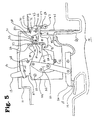
- Fig. 8, a partial sectional view of a multicontact thermomagnetic circuit breaker, arranged in a cast housing, with indication of a trip resulting from a ground leak (fault current), where the associated mechanism is omitted for the sake of better representation, and
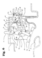
- Fig. 9, a representation similar to Fig. 8, with the exception that the circuit breaker is represented in a state resulting from tripping of an accessory.
-
- A
circuit breaker 10 arranged in a preformed housing is shown in Fig. 1 and consists of ahousing 11, anoperating mechanism 12, a control element (operating grip, handle) 13, acurrent path 14 and atrip unit 15. Aline connection 16 and aload connection 17 of thecurrent path 14 are connected with a protective circuit (not shown) via fastening elements (not shown). During closed circuit conditions, amovable contact 18 of amovable contact arm 20 lies on astationary contact 19 of theline connection 16 to produce an electric current flow in thecurrent path 14 through theline connection 16, thestationary contact 19, themovable contact 18, themovable contact arm 20, aflexible line 21 and theload connection 17. - The
operating mechanism 12 works in a fashion similar to that disclosed in US 3,158,717 and serves to open and close themovable contact arm 20. - The latched and closed state of the
operating mechanism 12 is represented in Fig. 2, where a mechanical supportingmember 22 in thehousing 11 forms a rotary bearing 23 at one end of aratchet lever 24. Aratchet lever surface 25 at the other end of the ratchet lever 24 opposite thebearing 23 is connected with aratchet surface 26 of afirst ratchet 27, which is seated rotary in the mechanical supportingmember 22. Asecond ratchet 29, which is seated rotary on a rotatingshaft 30 in the mechanical supportingmember 22, comprises aratchet finger 31, which cooperates with a supportingsurface 32 on thefirst ratchet 27. Thetrip unit 15 consists of amomentary reaction element 40, athermal reaction element 41, afirst tripping bar 42 and asecond tripping bar 43, thebars housing 11 on a commonrotary shaft 47. A first trip lever 44 and a second trip lever 45, which on alever shaft 46 are arranged rotary on the mechanical supportingmember 22, are in each instance arranged between thetripping bars second ratchet 29. The mode of operation of the momentary reaction elements and thethermal reaction elements trip unit 15 are described below with reference to Figures 3, 4, 5 and 6. - Operation of the
momentary reaction element 40 and themechanism 12 due to occurrence of a momentary overcurrent is explained in Figures 3 and 4, where thethermal reaction element 41, thesecond tripping bar 43 and thesecond trip lever 45 are omitted for the sake of better representation. Upon occurrence of a momentary overcurrent in thecurrent path 14, anarmature 80 with an armature bearing 81 is pulled up magnetically by amagnet 82, themagnet 82 being fastened in thehousing 11 by means of fasteningparts armature 80 cooperates with the first end of thefirst tripping bar 42 and produces clockwise rotation of thefirst tripping bar 42 about the tripping bar bearing 47, owing to which afirst hook 49 of thefirst trip lever 44 is released from the first ratchet surface of thefirst tripping bar 42. Thefirst trip lever 44 is pretensioned clockwise by the use of a spring (not shown), while afirst arm 51 of thefirst trip lever 44 is forcibly pressed against atrip pin 52 of thesecond ratchet 29, so that thesecond ratchet 29 executes a counterclockwise rotation about itsbearing 30. The counterclockwise rotation of thesecond ratchet 29 causes thefinger 31 of thesecond ratchet 29 to be released from the supportingsurface 32 of thefirst ratchet 27. The pretensioning force prevailing between theratchet lever surface 25 and theratchet surface 26 by the use of the spring (not shown) actuating the mechanism leads to clockwise rotation of thefirst ratchet 27 about itsbearing surface 28, whereupon thesurface 25 of theratchet lever 24 is released from thesurface 26 of thefirst ratchet 27. If theratchet lever surface 25 has been released from theratchet surface 26, the mechanism behaves in a manner similar to the manner described in US 3,158,717, in that themovable contact arm 20 is opened and the line to be protected is disconnected. - Fig. 3 shows the
operating mechanism 12 in the "latched" and "closed" state, where themovable contact 18 is in contact with thestationary contact 19, while Fig. 4 shows theoperating mechanism 12 in the "tripped" and "open" state, where themovable contact 18 is electrically separated from thestationary contact 19. The latched state of Fig. 3 shows afirst display 53 on asecond end 54 of thefirst tripping bar 42, which is arranged within thehousing 11 at a position in which it is not visible through afirst aperture 55 in thehousing 11. The tripped state of Fig. 4 shows thefirst display 53 of thesecond end 54 of thefirst tripping bar 42 at a position within thehousing 11 in which thefirst display 53 can be seen through theaperture 55 of thehousing 11, so that a display is provided in this fashion when the movable andstationary contacts momentary reaction element 40 to a momentary overcurrent condition. - Resetting of the
operating mechanism 12 and themomentary reaction element 40 to produce closing of the movable andstationary contacts current path 14 permits thearmature 80 to return to its resting position shown in Fig. 3 under the pretension of a restoring spring (not shown). Clockwise rotation of thehandle 13 of Fig. 4 about a handle bearing 56 of the mechanical supportingmember 22, supported by a handle-supportingmember 57, produces engagement of anoperating pin 58 on the handle-supportingmember 57 with afirst cam surface 59 of theratchet lever 24, so that thelever 24 is turned clockwise about its rotary bearing 23. - During clockwise rotation of the
ratchet lever 24, asecond cam surface 60 of theratchet lever 24 comes into engagement with thefirst ratchet 27 until theratchet surface 25 of theratchet lever 24 is arranged below theratchet surface 26 of thefirst ratchet 27, whereby engagement of theratchet surface 26 with theratchet lever surface 25 of Fig. 3 is made possible. Positioning of theratchet surface 26 on theratchet lever surface 25 permits thesecond ratchet 29 to execute a clockwise rotation about itsbearing 30 as a result of the force of a restoring spring (not shown), until astop pin 61 is in engagement with the mechanical supportingmember 22, whereby according to Fig. 3 thefinger 31 of thesecond ratchet 29 is in engagement with the supportingsurface 32 of thefirst ratchet 27. Clockwise rotation of thehandle 13 of Fig. 4 likewise causes engagement of the resettingsurface 62 of the handle-supportingmember 57 with the first resettingelement 63 of thefirst trip lever 44, whereby thefirst trip lever 44 is rotated counterclockwise about its lever bearing 46 and causes lifting of thefirst hook 49 of thefirst trip lever 44 above thefirst ratchet surface 50 of thefirst tripping bar 42. If thefirst hook 49 is located above thefirst ratchet surface 50, thefirst tripping bar 42 rotates counterclockwise about the bar bearing 47 under the force of a pre-tensioning spring (not shown), whereby according to Fig. 3 latching of thefirst hook 49 of thefirst trip lever 44 with thefirst ratchet surface 50 of thefirst tripping bar 42 is made possible. Closing of themovable contact arm 20 to bring themovable contact 18 together with thestationary contact 19 to form an electrical contact is produced by counterclockwise rotation of thehandle 13 about the handle bearing 56, whereby anelbow lever connection 64 is actuated under the force of a spring (not shown) actuating the mechanism in a manner similar to the manner disclosed in US 3,158,717, so that the movable andstationary contacts - The mode of operation of the
thermal reaction element 41 and themechanism 12 upon occurrence of an overload/overcurrent can be described according to Figures 5 and 6 where, for the sake of better illustration, themomentary reaction element 40, the first trippingbar 42 and thefirst trip lever 44 have been omitted from the figures. After occurrence of an overload/overcurrent in thecurrent path 14, thethermal reaction element 41, which is arranged in thecurrent path 14 at a bend (offset piece) 65, reacts and bends clockwise about the fastening point at the bend as a result of thermal heating of thethermal reaction element 41 and the difference in the coefficient of thermal expansion of the material components forming thethermal reaction element 41, whereby an adjustingscrew 66 is moved in the direction of the second trippingbar 43. Cooperation of thescrew 66 with the second trippingbar 43 produces clockwise rotation of the second trippingbar 43 about the bar bearing 47, whereby asecond hook 67 of thesecond trip lever 45 is carried away by asecond ratchet surface 68 of the second trippingbar 43. By means of a spring (not shown) thesecond trip lever 45 is pretensioned to cause a clockwise rotation, so that asecond arm 69 of thesecond trip lever 45 is pressed toward atrip pin 52 of thesecond ratchet 29 and consequently thesecond ratchet 29 is rotated counterclockwise about thebearing 30. Counterclockwise rotation of thesecond ratchet 29 causes thefinger 31 of thesecond ratchet 29 to be released from the supportingsurface 32 of thefirst ratchet 27 and hence to be no longer engaged. Application of a pretensioning force between theratchet lever surface 25 and theratchet surface 26, applied by a spring (not shown) actuating the mechanism, leads to clockwise rotation of thefirst ratchet 27 about bearingelement 28, where thesurface 25 of theratchet lever 24 is released from thesurface 26 of thefirst ratchet 27 and hence is no longer engaged. If theratchet lever surface 25 has been released from theratchet surface 26, the operating mechanism reacts in a manner similar to the manner as described in US 3,158,717 to open themovable contact arm 20, whereupon the line to be protected is disconnected. - Fig. 5 shows the
operating mechanism 12 in the "locked" and "closed" state, in which themovable contact 18 rests on thestationary contact 19, while Fig. 6 shows theoperating mechanism 12 in the "tripped" and "open" state, in which themovable contact 18 is electrically separated from thestationary contact 19. The locked state of Fig. 5 shows asecond display 70 on oneend 71 of the second trippingbar 43, which is arranged within thehousing 11 at a position in which thedisplay 70 is not visible through asecond aperture 72 in thehousing 11. The tripped state of Fig. 6 shows asecond display 70 on theend 71 of the second trippingbar 43 at a position within thehousing 11 in which thedisplay 70 can be seen through thesecond aperture 72 in thehousing 11, whereby a display is provided indicating that the movable andstationary contacts thermal reaction element 41 as a function of an overload/overcurrent condition. - Resetting of the
operating mechanism 12 and thethermal reaction element 41 for renewed closing of the movable andstationary contacts current path 14 permits thethermal reaction element 41 to return to its resting position shown in Fig. 5, which is produced as a result of cooling and relaxation of the internal stresses of the material components forming thethermal reaction element 41. Clockwise rotation of thehandle 13 of Fig. 6, which is supported by the handle-supportingmember 57, about thehandle shaft 56 of the mechanical supportingmember 22 causes engagement of theoperating pin 58 of the handle-supportingmember 57 with thefirst cam surface 59 of theratchet lever 24, so that thelever 24 is thereby rotated clockwise about itsbearing 23. During clockwise rotation of theratchet lever 24, thecam surface 60 of thelever 24 goes into engagement with thefirst ratchet 27, until thesurface 25 of theratchet lever 24 is arranged below thesurface 26 of thefirst ratchet 27, whereby according to Fig. 5 latching of theratchet surface 26 with theratchet lever surface 25 is produced. - Positioning of the
ratchet surface 26 on theratchet lever surface 25 causes clockwise rotation of thesecond ratchet 29 about itsbearing 30 under the force of a restoring spring (not shown) until thestop pin 61 engages with the mechanical supportingmember 22, whereby thefinger 31 of thesecond ratchet 29 engages with the supportingsurface 32 of thefirst ratchet 27 according to Fig. 5. - Clockwise rotation of the
handle 13 according to Fig. 6 likewise produces engagement of the resettingsurface 62 of the handle-supportingmember 57 with asecond resetting element 73 of thesecond trip lever 45, whereby thesecond trip lever 45 is rotated counterclockwise about itsbearing 56 and causes lifting of thesecond hook 67 of thesecond trip lever 45 above thesecond ratchet surface 68 of the second trippingbar 43. If thesecond hook 67 is located above thesecond ratchet surface 68, the second trippingbar 43 rotates counterclockwise about the tripping bar bearing 57 under the force of a pretensioning spring (not shown), whereby latching of thesecond hook 67 of thesecond trip lever 45 with thesecond ratchet surface 68 of the second trippingbar 43 according to Fig. 5 is made possible. Closing of themovable contact arm 20 to bring themovable contact 18 into contact with thestationary contact 19 is produced by counterclockwise rotation of thehandle 13, theelbow lever connection 64 thereby being operated under the force of the springs (not shown) actuating the mechanism in a manner similar to the manner described in US 3,158,717 for bringing the movable andstationary contacts - An alternative means for visual display of either a momentary or overload/overcurrent condition is shown in Fig. 7, where like reference numerals refer to like parts of Figures 1 to 6. Fig. 7 shows a tripped state resulting from an overload/overcurrent condition.
- The mode of operation of the
thermal reaction element 41 and themechanism 12 upon occurrence of an overload/overcurrent in the alternative means shown in Fig. 7 is similar to the mode of operation described for Figures 5 and 6 indicated above, where an overload/overcurrent in thecurrent path 14 causes clockwise bending (deflection) about the fastening point of the bend 65 of thethermal reaction element 41, whereby the adjustingscrew 66 is moved toward the second trippingbar 43 and hence the second trippingbar 43 is rotated clockwise about the tripping bar bearing 47 to disengage thesecond hook 67 of thesecond trip lever 45 from thesecond ratchet surface 68 of the second trippingbar 43. A pretensioning spring (not shown) provides the force for clockwise rotation of thesecond trip lever 45 about the lever bearing 46 when thesecond hook 67 is no longer in engagement with thesecond ratchet surface 68. Operation of thesecond ratchet 29, thefirst ratchet 27, theratchet lever 24, theelbow lever connection 64 and themovable contact arm 20 is produced in the fashion corresponding to the description of Figures 3 to 6. - The overload trip condition of Fig. 7 shows the
second display 70 on thesecond projection 90 of thesecond trip lever 45 in a position within thehousing 11 in which thesecond display 70 can be seen through thesecond aperture 72 of the housing, whereby a display is made provided indicating that the movable andstationary contacts thermal reaction element 41 corresponding to an overload/ overcurrent condition. - In contrast to the displays by means of the tripping
bars housing 11 of the circuit breaker, according to Fig. 7 display is effected by appropriately designed trip levers 44 and 45. - Resetting of the
operating mechanism 12 and thethermal reaction element 41 to produce renewed closing of the movable andstationary contacts - The mode of operation of the
momentary reaction element 40 and themechanism 12 upon occurrence of a momentary overcurrent within the alternative means of Fig. 7 is the same as that described for Figures 3 and 4, where a momentary overcurrent in thecurrent path 14 is produced such that thearmature 80 is pulled up magnetically bymagnets 82, so that the first trippingbar 42 performs a clockwise rotation about the tripping bar bearing 47 for disengaging thefirst hook 49 of thefirst trip lever 44 from thefirst ratchet surface 50 of the first trippingbar 42. A pretensioning spring (not shown) provides a force for rotating thefirst trip lever 44 clockwise about the lever bearing 46 when thefirst hook 49 is released from thefirst ratchet surface 50 and is no longer engaged. Operation of thesecond ratchet 29, thefirst ratchet 27, theratchet lever 24, theelbow lever connection 64 and themovable contact arm 20 is produced in the same fashion as in Figures 3 to 6. - The overload trip condition of Fig. 7 shows that the
second hook 67 of thesecond trip lever 45 is released from thesecond ratchet surface 68 of the second trippingbar 43, and thefirst hook 49 of thefirst trip lever 44 is still engaged with thefirst ratchet surface 50 of the first trippingbar 42. Since thefirst hook 49 is still engaged with thefirst ratchet surface 50, afirst display 53 on afirst projection 91 of thefirst trip lever 44 is arranged in a position within thehousing 11 in which it cannot be seen through thefirst aperture 55 in thehousing 11, whereby a display is provided indicating that the movable andstationary contacts momentary reaction element 40 due to a momentary overcurrent condition. If the movable andstationary contacts momentary reaction element 40 owing to a momentary overcurrent condition, thefirst hook 49 of thefirst trip lever 44 is released from engagement with thefirst ratchet surface 50 of the first trippingbar 42, whereby thefirst display 53 of afirst projection 91 of thefirst trip lever 44 is arranged in a position in thehousing 11 in which thefirst display 53 can be seen from the outside through thefirst aperture 55 in thehousing 11. - Resetting of the
operating mechanism 12 and themomentary reaction element 40 to produce renewed closing of the movable andstationary contacts - The visual display of a trip condition as a result of actuation by a ground leak/ accessory tripping means (ELD) is shown in Fig. 8, where the ground leak/accessory tripping means 100 is arranged in the
housing 11 adjacent to the arrangement of themechanism 12 or outside thehousing 11 and comprises acoil arrangement 101, atrip spring 102, atrip arm 103, asolenoid plunger arrangement 115 and areset lever 105. In the reset state areset plate 106 of thesolenoid plunger arrangement 115 rests on apermanent magnet 107 within thecoil arrangement 101, while thepermanent magnet 107 exerts a sufficient retaining force on thereset plate 106 to produce a counterweight for the opposed pretensioning force of thetrip spring 102. A trip signal is supplied by coil wires 108, which are electrically connected with acoil 109 in thecoil arrangement 101, and permits thecoil 109 to produce a magnetic field in such fashion that said magnetic field is opposed to the magnetic field of thepermanent magnet 107, whereby the pulling-up force between thereset plate 106 and thepermanent magnet 107 is nullified. Owing to the absence of pulling-up force between thereset plate 106 and thepermanent magnet 107, thereset plate 106 is rapidly moved away from thepermanent magnet 107 as a result of the pretensioning force of thetrip spring 102 pressing thetrip arm 103, thetrip arm 103 being an integral component of thesolenoid plunger arrangement 115. Thereset plate 106, thesolenoid plunger 104, thetrip arm 103 and anend cap 114 are components of thesolenoid plunger arrangement 115 and move together in unitary fashion. A rapid movement of thetrip arm 103 away from thepermanent magnet 107 and in the direction of the first and second trippingbars end 110 of thetrip arm 113 simultaneously striking thesecond end 54 of the first trippingbar 42 and thesecond end 71 of the second trippingbar 43 to drive the first and second trippingbars second hooks 49 and 67 (for clear representation, not shown in Fig. 8) are unlatched from the first and second ratchet surfaces 50 and 68, so that the mechanism 12 (for clear representation, not shown in Fig. 8) is actuated and themovable contact arm 20 is moved according to the description for Figures 3 to 6. The combined movement of the first and second trippingbars second display bars housing 11 in a position in which thedisplays second apertures housing 11, so that a display is provided indicating that the movable andstationary contacts trip arm 103 away from thepermanent magnet 107 in a tripped position likewise leads to rapid movement of theend cap 114 in the same direction, since the latter likewise is an integral component of thesolenoid plunger arrangement 115. In the tripped position theend cap 114 cooperates with an operatingrod 113 at one end of thereset lever 105 to produce clockwise rotation about a reset lever bearing 112, whereby a reset element 111 at an opposite end of thereset lever 105 is brought into a tripped position. - Resetting of the mechanism 12 (Fig. 1, adjacent arrangement) and the ground leak/accessory tripping means (ELD) 100 to produce renewed closing of the movable and
stationary contacts coil 109. After removal of the trip signal, rotation of the handle 13 (Fig. 1, adjacent arrangement) about the handle bearing 56 (Fig. 1), supported by the handle-supportingmember 57, causes a control surface (not shown) of the handle-supportingmember 57 to cooperate with the reset element 111, which extends through a dividing wall (not shown) of thehousing 11 in the mechanical arrangement, and produces counterclockwise rotation of thereset lever 105 about thereset lever bearing 112. Thecontrol rod 113 of thereset lever 105 cooperates with theend cap 114 of thesolenoid plunger arrangement 115 to drive thesolenoid plunger arrangement 115 and thereset plate 106 in the direction of thepermanent magnet 107 against the pretensioning force applied by thetrip spring 102. If thereset plate 106 reaches thepermanent magnet 107 and strikes it, the retaining force of thepermanent magnet 107 is sufficiently great to produce a counter force to the pretensioning force of thetrip spring 102, so that thesolenoid plunger arrangement 115 is held in the locked position and renewed locking of the mechanism 12 (Fig. 1, mechanical arrangement) and renewed closing of themovable contact arm 20 according to the description for Figures 3 to 6 can follow. - Visual display of a trip condition resulting from operation of an accessory tripping means (accessory) such as an undervoltage tripping means or a working current tripping means is shown in Fig. 9, where the
accessory 120 is arranged within thehousing 11 in an arrangement adjacent to that of themechanism 12 or outside thehousing 11, and comprises a signaling means throughcoil wires 121 to receive a trip signal, acoil arrangement 122 in acoil housing 123, and a trippingsolenoid plunger 124 for cooperation with themechanism 12 shown (in Fig. 1) for the purpose of opening the movable andstationary contacts coil wires 121 the trippingsolenoid plunger 124 is pressed against aninner surface 125 of thecoil housing 123 under the pretensioning force of a restoringspring 125 of thecoil arrangement 122, whereby a separating slot is produced between acontrol plate 127 of the trippingsolenoid plunger 124 and thetrip pin 52. A trip signal to thecoil wires 121, which in each instance are electrically connected with acoil 128 in thecoil arrangement 122, permits thecoil 128 to produce a magnetic field for exerting a magnetic pulling-up force on asolenoid plunger member 129 for pulling asolenoid plunger end 130 of thesolenoid plunger member 129 of thesolenoid plunger 124 and thecontrol plate 127 downward in the direction of the pretensioning force of a restoringspring 126, so that thecontrol plate 127 strikes thetrip pin 52, which extends through a dividing wall (not shown) of thehousing 11 in the direction of the accessory arrangement adjacent to the mechanical arrangement, thesecond ratchet 29 being rotated counter-clockwise about thebearing 30. Rotation of thesecond ratchet 29 is followed by operation of thefirst ratchet 27, theratchet lever 24, theelbow lever connection 64 and themovable contact arm 20 in the fashion corresponding to the description referring to Figures 3 to 6. Since the trip condition as a result of operation of anaccessory 120 does not affect the first trippingbar 42, the second trippingbar 43, thefirst trip lever 44 or thesecond trip lever 45, the positions of the first andsecond displays housing 11 and are not visible through the first andsecond apertures housing 11, so that only the tripped position of thehandle 13 is visible and serves to indicate that an accessory trip condition exists. - Resetting of the mechanism 12 (Fig. 1, adjacent mechanical arrangement) and the
accessory 120 to produce renewed closing of the movable andstationary contacts coil wires 121 for de-energizing thecoil 128 to be removed. Removal of the tripping signal likewise removes the magnetic field generated by means of thecoil 128, whereby the magnetically generated tripping force is nullified as counter force to the force of the restoringspring 126, so that thespring 126 cooperates with thesolenoid plunger end 130 to lift thesolenoid plunger member 129, the trippingsolenoid plunger 124 and thecontrol plate 127 until thesolenoid plunger end 130 stops at theinner surface 125 of thecoil housing 123 and thecontrol plate 127 is released from thetrip pin 52 to form a separating slot between thecontrol plate 127 and thetrip pin 52. If the separating slot has been formed between thecontrol plate 127 and thetrip pin 52, thehandle 13 supported by the handle-supportingmember 57 can be rotated clockwise about the handle bearing 56 (Fig. 1, adjacent mechanical arrangement) to produce renewed latching of themechanism 12 and renewed closing of themovable contact arm 20 according to the description referring to Figures 3 to 6. - The thermomagnetic circuit breaker in a preformed housing therefore comprises a display means for the selective display of reasons for trip. Tripping bars operable independently of one another provide a trip function as well as a display function. Alternatively, a display may be effected with additional trip levers. Combinations of independently operable tripping bars and an operating handle provide a display means for the display of an overload, momentary, ground leak or accessory trip condition.
Claims (18)
- Circuit breaker, with:a housing (11) and a current path (14) within the housing (11) for connecting a line to be protected;at least one pair of separable contacts (18, 19) within the current path (14) for connecting and separating the line to be protected;an operating mechanism (12) within the housing (11), where the operating mechanism comprises a ratchet lever (24) and an actuating spring for separating the separable contacts (18, 19) as a function of a command;an operating handle (13) arranged on the operating mechanism (12) for external operation of the operating mechanism through an access aperture in the housing (11);a trip unit (15) within the housing (11), where the trip unit has a magnetic reaction element (40) for actuation of the operating mechanism (12) corresponding to occurrence of a first line disconnect condition, and a thermal reaction element (41) for actuation of the operating mechanism (12) corresponding to occurrence of a second line disconnect condition;a first trip ratchet (27) between the ratchet lever (24) and a second trip ratchet (29), where the first trip ratchet is provided for preventing the ratchet lever (24) from releasing the actuating spring under steady current conditions of the current path (14), and where the second trip ratchet (29) is provided with a pretensioning means for holding back the first trip ratchet for continued retention of the ratchet lever (24) under steady current conditions of the current path (14);a first trip lever (44) near the second trip ratchet (29), with a first end for cooperating with the second trip ratchet (29) to nullify retention between the second trip ratchet (29) and the first trip ratchet (27), and a third end of the first trip lever (44) for cooperating with the operating mechanism (12) to permit renewed latching of the first and second trip ratchets (27, 29) and renewed closing of the contacts (18, 19);and a first tripping bar (42), arranged rotary within the trip unit (15), with a first, second and third end, where the first end of the first tripping bar (42) cooperates with the magnetic reaction element (40), the second end of the first tripping bar cooperates with the second end of the first trip lever (44), and the third end of the first tripping bar cooperates with an observation window (55) in the upper surface of the housing (11), for simultaneous release of the first and second ratchets (27, 29) to separate the contacts (18, 19) corresponding to occurrence of the first overcurrent condition and to provide a display indicating this state.
- Circuit breaker according to Claim 1, with a second tripping bar (43), arranged rotary within the trip unit (15), with a first, second and third end, where the first end of the second tripping bar cooperates with the thermal reaction element (41), the second end of the second tripping bar cooperates with a second end of a second trip lever (45) and the third end of the second tripping bar cooperates with the viewing window (55), for simultaneous release of the first and second ratchets (27, 29) to separate the contacts (18, 19) corresponding to occurrence of the second disconnect condition and to provide a display of the same.
- Circuit breaker, with:a housing (11) and a current path (14) within the housing (11) for connecting a line to be protected;at least one pair of separable contacts (18, 19) within the current path (14) for connecting and separating the line to be protected;an operating mechanism (12) within the housing (11), where the operating mechanism comprises a ratchet lever (24) and an actuating spring for separating the separable contacts (18, 19) as a function of a command;an operating handle (13) arranged on the operating mechanism (12) for external operation of the operating mechanism through an access opening in the housing (11);a trip unit (15) within the housing (11), where the trip unit has a magnetic reaction element (40) for actuation of the operating mechanism (12) corresponding to occurrence of a first line disconnect condition, and a thermal reaction element (41) for actuation of the operating mechanism (12) corresponding to occurrence of a second line disconnect condition;a first trip ratchet (27) between the ratchet lever (24) and a second trip ratchet (29), where the first trip ratchet is provided for preventing the ratchet lever (24) from releasing the actuating spring under steady current conditions of the current path (14), and where the second trip ratchet (29) is provided with a pretensioning means for holding back the first trip ratchet for continued retention of the ratchet lever (24) under steady current conditions of the current path (14);a first trip lever (24) near the second trip ratchet (29), with a first end for cooperating with the second trip ratchet (29) to nullify retention between the second trip ratchet (29) and the first trip ratchet (27), and a third end of the first trip lever (44) for cooperating with the operating mechanism (12) to permit renewed latching of the first and second trip ratchets (27, 29) and renewed closing of the contacts (18, 19);and a first tripping bar (42), arranged rotary within the trip unit (15), with a first and second end, where the first end of the first tripping bar (42) cooperates with the magnetic reaction element (40), the second end of the first tripping bar cooperates with the second end of the first trip lever (44), and a fourth end of the first tripping bar cooperates with an observation window (55) in the upper surface of the housing (11), for simultaneous release of the first and second ratchets (27, 29) to separate the contacts (18, 19) corresponding to occurrence of the first overcurrent condition and to provide a display indicating this state.
- Circuit breaker according to Claim 3, with a second tripping bar (43), arranged within the trip unit (15), where the second tripping bar (43) has a first and second end, and the first end of the second tripping bar (43) cooperates with the thermal reaction element (41) and the second end of the second tripping bar (43) cooperates with a second end of a second trip lever (45), a fourth end of the second tripping bar cooperates with a viewing window (55) in the upper surface of the housing (11) for simultaneous release of the first and second ratchets (27, 29) to separate the contacts (18, 19) after occurrence of the second disconnect condition and to provide a corresponding display of the same.
- Circuit breaker according to Claim 2 or Claim 4, where the second trip lever (45) near the second trip ratchet (29) has a first end for cooperating with the second trip ratchet (29) to nullify retention between the second trip ratchet (29) and the first trip ratchet (27).
- Circuit breaker according to Claim 2 or Claim 4, where the second trip lever (45) has a third end for cooperating with the operating mechanism (12) to permit renewed latching of the ratchets (27, 29) and renewed closing of the contacts (18, 19).
- Circuit breaker according to Claim 2 or Claim 4, where the operating handle assumes a predetermined position within the access opening to provide a display of occurrence of the first, second, a third and a fourth disconnect condition.
- Circuit breaker according to Claim 2 or Claim 4, where the first and second tripping bars (42, 43) are arranged rotary on a common bearing.
- Circuit breaker according to Claim 2 or Claim 4, where the first disconnect condition comprises a momentary overcurrent.
- Circuit breaker according to Claim 2 or Claim 4, where the second disconnect condition comprises a longer-lasting overcurrent.
- Circuit breaker according to Claim 2 or Claim 4, where the second disconnect condition additionally comprises a momentary overcurrent.
- Circuit breaker according to Claim 7, where a first projection on the first tripping bar (42) bears a first display for visual display of the first disconnect condition through the viewing window (55), and a first projection of the second tripping bar bears a second display for visual display of the second disconnect condition through the viewing window (55).
- Circuit breaker according to Claim 2 or Claim 4, where a ground leak reaction element (100) is arranged within or without the housing (11) to actuate the first and second tripping bars (42, 43) upon occurrence of a ground leak condition.
- Circuit breaker according to Claim 7, where the third disconnect condition comprises a ground leak condition.
- Circuit breaker according to Claim 12, where the third disconnect condition is displayed visually by display of the first and second displays (53, 70) through the viewing window (55).
- Circuit breaker according to Claim 7, where the fourth disconnect condition comprises an accessory trip condition.
- Circuit breaker according to Claim 16, where an accessory trip element (120) is arranged within the housing to actuate the second trip ratchet (29) after occurrence of the fourth disconnect condition, where the fourth disconnect condition is displayed visually by a predetermined position of the operating handle.
- Circuit breaker according to Claim 7, where a projection (91) of the first trip lever (44) bears a first display (53) for visual display of the first disconnect condition through the viewing window (55, 72), and a projection (90) of the second trip lever (45) bears a second display (70) for visual display of the second disconnect condition through the viewing window (55, 72).
Applications Claiming Priority (2)
| Application Number | Priority Date | Filing Date | Title |
|---|---|---|---|
| DE19819242A DE19819242B4 (en) | 1998-04-29 | 1998-04-29 | Thermomagnetic circuit breaker |
| DE19819242 | 1998-04-29 |
Publications (3)
| Publication Number | Publication Date |
|---|---|
| EP0954002A2 true EP0954002A2 (en) | 1999-11-03 |
| EP0954002A3 EP0954002A3 (en) | 2000-06-14 |
| EP0954002B1 EP0954002B1 (en) | 2006-04-19 |
Family
ID=7866231
Family Applications (1)
| Application Number | Title | Priority Date | Filing Date |
|---|---|---|---|
| EP99303234A Expired - Lifetime EP0954002B1 (en) | 1998-04-29 | 1999-04-27 | Thermal magnetic circuit breakers |
Country Status (12)
| Country | Link |
|---|---|
| US (1) | US6225881B1 (en) |
| EP (1) | EP0954002B1 (en) |
| JP (1) | JP4240171B2 (en) |
| CN (1) | CN1258796C (en) |
| DE (1) | DE19819242B4 (en) |
| ES (1) | ES2262291T3 (en) |
| HU (1) | HU223995B1 (en) |
| ID (1) | ID22559A (en) |
| PL (1) | PL332816A1 (en) |
| PT (1) | PT954002E (en) |
| SG (1) | SG74139A1 (en) |
| TW (1) | TW492031B (en) |
Cited By (11)
| Publication number | Priority date | Publication date | Assignee | Title |
|---|---|---|---|---|
| EP1111642A2 (en) * | 1999-12-23 | 2001-06-27 | General Electric Company | Shunt for indirectly heated bimetallic strip |
| WO2005031778A1 (en) * | 2003-10-01 | 2005-04-07 | Moeller Gebäudeautomation KG | Protective circuit breaker |
| WO2006018416A1 (en) * | 2004-08-19 | 2006-02-23 | Siemens Aktiengesellschaft | Safety switch device comprising an electrical display, and corresponding method |
| WO2007090820A1 (en) * | 2006-02-08 | 2007-08-16 | Moeller Gmbh | Device for triggering an electric switchgear |
| WO2012120327A1 (en) * | 2011-03-07 | 2012-09-13 | Larsen & Toubro Limited | An enhanced latch meachanism for use in circuit breakers |
| WO2013154801A1 (en) * | 2012-04-13 | 2013-10-17 | Siemens Industry, Inc. | Low tripping level circuit breakers, tripping units, and methods |
| WO2013188080A1 (en) * | 2012-06-12 | 2013-12-19 | Schneider Electric USA, Inc. | Circuit breaker thermal load visual gauge |
| FR2994765A1 (en) * | 2012-08-22 | 2014-02-28 | Wenzhou New Blue Sky Electrical Co Ltd | HIGH INTENSITY MINIATURE CIRCUIT BREAKER |
| EP2725600A1 (en) * | 2012-10-24 | 2014-04-30 | ABB Schweiz AG | Low voltage protection device |
| EP2733720A1 (en) | 2012-11-19 | 2014-05-21 | Schneider Electric Industries SAS | Thermal-magnetic tripping device for tripping a polyphase circuit breaker |
| EP3454355A1 (en) * | 2017-09-07 | 2019-03-13 | Carling Technologies Inc. | Circuit interrupter with status indication |
Families Citing this family (35)
| Publication number | Priority date | Publication date | Assignee | Title |
|---|---|---|---|---|
| DE10220665A1 (en) * | 2002-05-10 | 2003-11-20 | Abb Patent Gmbh | Switch for protecting an electric motor has a contact point with fixed and movable contact pieces and a switch latch to act on the contact point. |
| KR100549850B1 (en) * | 2003-11-26 | 2006-02-06 | 엘에스산전 주식회사 | Voltage trip attachment of circuit breaker |
| JP4310232B2 (en) * | 2004-05-07 | 2009-08-05 | 三菱電機株式会社 | Circuit breaker |
| DE102004040288B4 (en) * | 2004-08-19 | 2007-09-20 | Siemens Ag | Circuit breaker with short-circuit and overload trip indication and corresponding procedure |
| DE102006016648A1 (en) * | 2006-04-08 | 2007-10-11 | Hella Kgaa Hueck & Co. | Bistable electromagnetic high current switch for e.g. motor vehicle battery, has electrothermal actuator unit provided for closing load current path, and electromagnetic actuator unit provided for opening load current path |
| DE102006027140A1 (en) * | 2006-06-12 | 2007-12-13 | Ellenberger & Poensgen Gmbh | breaker |
| JP5081466B2 (en) * | 2007-02-16 | 2012-11-28 | パナソニック株式会社 | Electronic breaker |
| JP5081467B2 (en) * | 2007-02-16 | 2012-11-28 | パナソニック株式会社 | Electronic breaker |
| KR100905021B1 (en) * | 2007-08-07 | 2009-06-30 | 엘에스산전 주식회사 | Thermal overload trip apparatus and trip sensitivity adjusting method for the same |
| KR100881365B1 (en) * | 2007-08-07 | 2009-02-02 | 엘에스산전 주식회사 | Trip sensitivity adjusting method for thermal overload protection apparatus |
| FR2926923B1 (en) * | 2008-01-28 | 2010-03-26 | Hager Electro Sas | SYSTEM FOR SIGNALING AN ELECTRICAL FAULT IN A CUTTING APPARATUS |
| CN101599395B (en) * | 2008-06-05 | 2011-06-29 | 浙江正泰电器股份有限公司 | Auxiliary disengaging mechanism for breaker |
| JP2010232058A (en) * | 2009-03-27 | 2010-10-14 | Fuji Electric Fa Components & Systems Co Ltd | Thermal overload relay |
| JP4906881B2 (en) * | 2009-03-27 | 2012-03-28 | 富士電機機器制御株式会社 | Thermal overload relay |
| JP4706772B2 (en) * | 2009-03-27 | 2011-06-22 | 富士電機機器制御株式会社 | Thermal overload relay |
| GB0915379D0 (en) * | 2009-09-03 | 2009-10-07 | Deepstream Technologies Ltd | Miniature circuit breaker |
| US8350168B2 (en) | 2010-06-30 | 2013-01-08 | Schneider Electric USA, Inc. | Quad break modular circuit breaker interrupter |
| CN102347171B (en) * | 2010-07-30 | 2014-03-26 | 上海良信电器股份有限公司 | Device for distinguishing and indicating fault of thermomagnetic tripping device |
| KR101759594B1 (en) * | 2011-06-24 | 2017-07-20 | 엘에스산전 주식회사 | A circuit braker |
| US8542083B2 (en) * | 2011-09-23 | 2013-09-24 | Eaton Corporation | Collapsible mechanism for circuit breakers |
| DE102012200922A1 (en) | 2012-01-23 | 2013-07-25 | Siemens Aktiengesellschaft | Electric switch |
| US9230768B2 (en) * | 2012-02-28 | 2016-01-05 | Siemens Aktiengesellschaft | Circuit breaker thermal-magnetic trip units and methods |
| WO2013137846A1 (en) * | 2012-03-12 | 2013-09-19 | Siemens Aktiengesellschaft | Circuit breaker trip blocking apparatus, systems, and methods of operation |
| JP5961517B2 (en) * | 2012-10-04 | 2016-08-02 | 富士通コンポーネント株式会社 | Switch device |
| CN105074864A (en) * | 2013-04-11 | 2015-11-18 | 松下知识产权经营株式会社 | Operation display mechanism, circuit breaker, compound breaker, and display member |
| FR3007573B1 (en) * | 2013-06-20 | 2015-07-17 | Schneider Electric Ind Sas | TRIGGER AND METHOD FOR MANUFACTURING SUCH TRIGGER |
| US10217590B2 (en) * | 2014-05-13 | 2019-02-26 | Schneider Electric USA, Inc. | Miniature circuit breaker color-coded state indicator |
| US9324528B1 (en) * | 2014-11-17 | 2016-04-26 | General Electric Company | Magnetic trip mechanism for circuit breaker |
| US10177543B2 (en) * | 2015-11-15 | 2019-01-08 | M&I Electric Industries | Electrical switchgear manual safety system and mechanisms |
| CN107359086B (en) * | 2016-05-10 | 2019-11-29 | 上海诺雅克电气有限公司 | The indicating fault auxiliary contact of breaker |
| CN107644791B (en) * | 2017-10-31 | 2020-05-05 | 浙江天正电气股份有限公司 | Reclosing feedback mechanism and circuit breaker with same |
| CN108461357A (en) * | 2018-03-21 | 2018-08-28 | 上海良信电器股份有限公司 | A kind of divide-shut brake instruction device of breaker operating device |
| DE102018216210A1 (en) * | 2018-09-24 | 2020-03-26 | Siemens Aktiengesellschaft | Quick-release latch, release mechanism and quick earth electrode, quick switch or short-circuiter |
| DE102019209747B3 (en) * | 2019-07-03 | 2020-10-08 | Ellenberger & Poensgen Gmbh | Circuit breaker |
| US11710612B2 (en) * | 2021-05-14 | 2023-07-25 | Siemens Industry, Inc. | Molded case circuit breaker with terminal cover having emboss guides for cable box cover alignment and fixing |
Citations (3)
| Publication number | Priority date | Publication date | Assignee | Title |
|---|---|---|---|---|
| US3205325A (en) * | 1963-06-19 | 1965-09-07 | Gen Electric | Circuit breaker trip device |
| US4090158A (en) * | 1975-12-24 | 1978-05-16 | Komao Oeda | Circuit breaker |
| EP0651416A1 (en) * | 1993-10-27 | 1995-05-03 | Circuit Breaker Industries Limited | A circuit breaker |
Family Cites Families (216)
| Publication number | Priority date | Publication date | Assignee | Title |
|---|---|---|---|---|
| US2340682A (en) | 1942-05-06 | 1944-02-01 | Gen Electric | Electric contact element |
| US2719203A (en) | 1952-05-02 | 1955-09-27 | Westinghouse Electric Corp | Circuit breakers |
| US2937254A (en) | 1957-02-05 | 1960-05-17 | Gen Electric | Panelboard unit |
| US3116388A (en) * | 1960-12-20 | 1963-12-31 | Gen Electric | Circuit breaker trip assembly |
| US3162739A (en) * | 1962-06-25 | 1964-12-22 | Gen Electric | Electric circuit breaker with improved trip means |
| US3158717A (en) * | 1962-07-18 | 1964-11-24 | Gen Electric | Electric circuit breaker including stop means for limiting movement of a toggle linkage |
| US3197582A (en) | 1962-07-30 | 1965-07-27 | Fed Pacific Electric Co | Enclosed circuit interrupter |
| US3171927A (en) * | 1962-11-09 | 1965-03-02 | Gen Electric | Circuit breaker with remote tripindicating means |
| DE1227978B (en) | 1963-10-04 | 1966-11-03 | Licentia Gmbh | Electrical switchgear, in particular contactor |
| US3307002A (en) | 1965-02-04 | 1967-02-28 | Texas Instruments Inc | Multipole circuit breaker |
| US3401363A (en) * | 1966-11-10 | 1968-09-10 | Square D Co | Multipole circuit breaker with trip indicator |
| DE1763717B1 (en) | 1967-07-24 | 1971-08-12 | Terasaki Denki Sangyo Kk | CURRENT LIMITING QUICK SWITCH |
| US3539867A (en) * | 1968-08-26 | 1970-11-10 | Federal Pacific Electric Co | Ground-fault protection systems |
| US3596219A (en) * | 1969-11-25 | 1971-07-27 | Square D Co | Circuit breaker with trip indicator |
| US3631369A (en) | 1970-04-27 | 1971-12-28 | Ite Imperial Corp | Blowoff means for circuit breaker latch |
| US3803455A (en) | 1973-01-02 | 1974-04-09 | Gen Electric | Electric circuit breaker static trip unit with thermal override |
| US3883781A (en) * | 1973-09-06 | 1975-05-13 | Westinghouse Electric Corp | Remote controlled circuit interrupter |
| FR2360171A1 (en) | 1976-07-30 | 1978-02-24 | Unelec | CIRCUIT BREAKER CONTROL MECHANISM |
| FR2361737A1 (en) | 1976-08-09 | 1978-03-10 | Unelec | CIRCUIT BREAKER WITH LOCKING DEVICE FOR THE CONTROL HANDLE IN THE EVENT OF WELDING OF THE CONTACTS |
| US4158119A (en) | 1977-07-20 | 1979-06-12 | Gould Inc. | Means for breaking welds formed between circuit breaker contacts |
| US4144513A (en) | 1977-08-18 | 1979-03-13 | Gould Inc. | Anti-rebound latch for current limiting switches |
| FR2410353A1 (en) | 1977-11-28 | 1979-06-22 | Merlin Gerin | Polarised relay for differential circuit breaker - has magnetic yoke having two L=shaped legs, one carrying de-energising coil and other completing loop with permanent magnet |
| US4166988A (en) | 1978-04-19 | 1979-09-04 | General Electric Company | Compact three-pole circuit breaker |
| FR2429487A1 (en) | 1978-06-23 | 1980-01-18 | Merlin Gerin | CIRCUIT BREAKER WITH REMOVABLE TRIGGER BLOCK |
| US4220934A (en) | 1978-10-16 | 1980-09-02 | Westinghouse Electric Corp. | Current limiting circuit breaker with integral magnetic drive device housing and contact arm stop |
| US4259651A (en) | 1978-10-16 | 1981-03-31 | Westinghouse Electric Corp. | Current limiting circuit interrupter with improved operating mechanism |
| US4255732A (en) | 1978-10-16 | 1981-03-10 | Westinghouse Electric Corp. | Current limiting circuit breaker |
| FR2452175A1 (en) | 1979-03-23 | 1980-10-17 | Alsthom Unelec Sa | ELECTRICAL AIR CUT-OFF APPARATUS PROVIDED WITH A SHORT-CIRCUIT INDICATOR DEVICE |
| US4263492A (en) | 1979-09-21 | 1981-04-21 | Westinghouse Electric Corp. | Circuit breaker with anti-bounce mechanism |
| US4297663A (en) | 1979-10-26 | 1981-10-27 | General Electric Company | Circuit breaker accessories packaged in a standardized molded case |
| IT1129691B (en) | 1980-01-31 | 1986-06-11 | Elettromeccanica Spa Cge Comp | RAPID EXTINGUISHING COMPLEX OF THE ELECTRIC ARC IN INTERRUPTION DEVICES SUCH AS ELECTRIC SWITCHES |
| FR2478368A1 (en) | 1980-03-12 | 1981-09-18 | Merlin Gerin | MANEUVER MECHANISM FOR TETRAPOLAR CIRCUIT BREAKER |
| JPS613106Y2 (en) * | 1980-04-10 | 1986-01-31 | ||
| US4301342A (en) | 1980-06-23 | 1981-11-17 | General Electric Company | Circuit breaker condition indicator apparatus |
| DE8023509U1 (en) | 1980-08-29 | 1980-11-27 | Siemens Ag, 1000 Berlin Und 8000 Muenchen | Low voltage circuit breaker for locking lever |
| DE3033213C2 (en) | 1980-08-29 | 1982-10-21 | Siemens AG, 1000 Berlin und 8000 München | Low voltage circuit breaker with a locking lever |
| DE3034790A1 (en) | 1980-09-15 | 1982-03-25 | Siemens AG, 1000 Berlin und 8000 München | CIRCUIT BREAKER |
| US4541032A (en) * | 1980-10-21 | 1985-09-10 | B/K Patent Development Company, Inc. | Modular electrical shunts for integrated circuit applications |
| JPS57102281U (en) * | 1980-12-16 | 1982-06-23 | ||
| DE3047360C2 (en) | 1980-12-16 | 1987-08-20 | Karl Pfisterer Elektrotechnische Spezialartikel Gmbh & Co Kg, 7000 Stuttgart | Switching strip |
| DE3110960A1 (en) | 1981-03-20 | 1982-09-30 | Basf Ag, 6700 Ludwigshafen | ELECTROPHOTOGRAPHIC RECORDING MATERIAL |
| US4360852A (en) | 1981-04-01 | 1982-11-23 | Allis-Chalmers Corporation | Overcurrent and overtemperature protective circuit for power transistor system |
| US4409573A (en) * | 1981-04-23 | 1983-10-11 | Siemens-Allis, Inc. | Electromagnetically actuated anti-rebound latch |
| FR2505553A1 (en) * | 1981-05-07 | 1982-11-12 | Merlin Gerin | MULTIPOLAR CIRCUIT BREAKER WITH INTERCHANGEABLE MAGNETOTHERMIC TRIGGER |
| FR2506066A1 (en) * | 1981-05-18 | 1982-11-19 | Merlin Gerin | MANEUVERING MECHANISM OF A LOW VOLTAGE MULTIPOLAR ELECTRIC CIRCUIT BREAKER |
| FR2512582A1 (en) | 1981-09-10 | 1983-03-11 | Merlin Gerin | Tamperproof differential relay - uses screw-in cover to clip together two modules of earth leakage relay |
| FR2514195A1 (en) * | 1981-10-05 | 1983-04-08 | Merlin Gerin | MULTIPOLAR CIRCUIT BREAKER WITH REMOVABLE TRIGGER BLOCK |
| US4435690A (en) * | 1982-04-26 | 1984-03-06 | Rte Corporation | Primary circuit breaker |
| US4658322A (en) * | 1982-04-29 | 1987-04-14 | The United States Of America As Represented By The Secretary Of The Navy | Arcing fault detector |
| US4470027A (en) * | 1982-07-16 | 1984-09-04 | Eaton Corporation | Molded case circuit breaker with improved high fault current interruption capability |
| IT8223118V0 (en) * | 1982-10-07 | 1982-10-07 | Sace Spa | ELECTRIC SWITCH WITH STOPPING THE CONTROL LEVER STROKE IN CASE OF WELDING THE CONTACTS. |
| US4492941A (en) | 1983-02-18 | 1985-01-08 | Heinemann Electric Company | Circuit breaker comprising parallel connected sections |
| US4488133A (en) * | 1983-03-28 | 1984-12-11 | Siemens-Allis, Inc. | Contact assembly including spring loaded cam follower overcenter means |
| FR2547122B1 (en) * | 1983-06-03 | 1985-07-05 | Merlin Gerin | SELECTIVE ELECTRONIC TRIGGER ASSOCIATED WITH A LIMITING CIRCUIT BREAKER |
| JPS6068524A (en) * | 1983-09-21 | 1985-04-19 | 三菱電機株式会社 | Circuit breaker |
| FR2553929B1 (en) | 1983-10-21 | 1986-08-01 | Merlin Gerin | CONTROL MECHANISM OF A LOW VOLTAGE MULTIPOLAR CIRCUIT BREAKER |
| FR2553943B1 (en) | 1983-10-24 | 1986-04-11 | Merlin Gerin | RESIDUAL DIFFERENTIAL DEVICE PROVIDED WITH A DEVICE FOR MONITORING THE ELECTRONIC POWER SOURCE |
| DE3347120A1 (en) * | 1983-12-22 | 1985-07-11 | Siemens AG, 1000 Berlin und 8000 München | ELECTRO-DYNAMIC OPENING CONTACT SYSTEM |
| IT1173269B (en) * | 1984-02-15 | 1987-06-18 | Cge Comp Gen Elettromecc | COMBINATION OF COUPLING CONNECTION AND RELEASE DEVICE TO AVOID THE CLOSING OF THE CONTACTS OF AN AUTOMATIC SWITCH AFTER AN OPENING DUE TO SHORT CIRCUIT |
| US4550360A (en) * | 1984-05-21 | 1985-10-29 | General Electric Company | Circuit breaker static trip unit having automatic circuit trimming |
| US4672501A (en) * | 1984-06-29 | 1987-06-09 | General Electric Company | Circuit breaker and protective relay unit |
| US4589052A (en) * | 1984-07-17 | 1986-05-13 | General Electric Company | Digital I2 T pickup, time bands and timing control circuits for static trip circuit breakers |
| JPS6132324A (en) * | 1984-07-20 | 1986-02-15 | 富士電機株式会社 | Internal accessory mounting structure of wiring breaker |
| IT1175633B (en) * | 1984-08-14 | 1987-07-15 | Cge Spa | Contact arrangement for current limiting circuit breaker |
| DE3431288A1 (en) * | 1984-08-23 | 1986-03-06 | Siemens AG, 1000 Berlin und 8000 München | CONTACT ARRANGEMENT FOR LOW VOLTAGE CIRCUIT BREAKERS WITH A TWO-ARM CONTACT LEVER |
| US4631625A (en) * | 1984-09-27 | 1986-12-23 | Siemens Energy & Automation, Inc. | Microprocessor controlled circuit breaker trip unit |
| US4612430A (en) * | 1984-12-21 | 1986-09-16 | Square D Company | Anti-rebound latch |
| FR2578092B1 (en) | 1985-02-25 | 1987-03-06 | Merlin Gerin | CIRCUIT BREAKER WITH STATIC TRIGGER WITH SAMPLING AND LOCK AT THE LAST SIGNAL CRETE |
| FR2578113B1 (en) * | 1985-02-25 | 1988-04-15 | Merlin Gerin | DIGITAL STATIC TRIGGER WITH OPTIONAL FUNCTIONS FOR AN ELECTRIC CIRCUIT BREAKER |
| FR2578091B1 (en) * | 1985-02-25 | 1988-08-05 | Merlin Gerin | CIRCUIT BREAKER WITH DIGITAL STATIC TRIGGER PROVIDED WITH A CALIBRATION CIRCUIT |
| FR2578112B1 (en) * | 1985-02-25 | 1988-03-18 | Merlin Gerin | CIRCUIT BREAKER WITH STATIC TRIGGER WITH DIGITAL PROCESSING CHAIN SHUNTE BY AN ANALOGUE PROCESSING CHAIN |
| FR2578090B1 (en) | 1985-02-25 | 1989-12-01 | Merlin Gerin | CIRCUIT BREAKER WITH DIGITAL STATIC TRIGGER WITH REVERSE TIME TRIGGERING FUNCTION |
| FR2578093B1 (en) | 1985-02-27 | 1987-03-06 | Merlin Gerin | UNIPOLAR AND NEUTRAL DIFFERENTIAL CIRCUIT BREAKER |
| US4642431A (en) * | 1985-07-18 | 1987-02-10 | Westinghouse Electric Corp. | Molded case circuit breaker with a movable electrical contact positioned by a camming spring loaded clip |
| DE3679291D1 (en) | 1985-10-31 | 1991-06-20 | Merlin Gerin | KINEMATIC TRANSMISSION CHAIN BETWEEN THE CONTROL MECHANISM AND THE POLES OF AN ELECTRIC LOAD SWITCH WITH A SPRAYED INSULATION HOUSING. |
| FR2589627B1 (en) | 1985-10-31 | 1988-08-26 | Merlin Gerin | CONTROL MECHANISM FOR LOW VOLTAGE ELECTRIC CIRCUIT BREAKER |
| DE3688838T2 (en) | 1986-01-10 | 1994-03-03 | Merlin Gerin | Static release with test circuit for electrical circuit breakers. |
| ES2020284B3 (en) | 1986-02-28 | 1991-08-01 | Merlin Gerin | CURRENT CUTTING DEVICE WITH STATIC SWITCH AND PROTECTION CIRCUIT BREAKER. |
| FR2596576B1 (en) | 1986-03-26 | 1988-05-27 | Merlin Gerin | SELF-BLOWING ELECTRIC CIRCUIT BREAKER WITH IMPROVED DIELECTRIC HOLD |
| FR2598266B1 (en) | 1986-04-30 | 1994-02-18 | Merlin Et Gerin | INSTANT STATIC TRIGGER FOR A LIMITING CIRCUIT BREAKER |
| FR2602610B1 (en) | 1986-08-08 | 1994-05-20 | Merlin Et Gerin | STATIC TRIGGER OF AN ELECTRIC CIRCUIT BREAKER WITH CONTACT WEAR INDICATOR |
| FR2604295B1 (en) | 1986-09-23 | 1988-12-02 | Merlin Gerin | ELECTRICAL DIFFERENTIAL PROTECTION DEVICE WITH TEST CIRCUIT |
| FR2604294B1 (en) | 1986-09-23 | 1994-05-20 | Merlin Et Gerin | MULTIPOLAR DIFFERENTIAL CIRCUIT BREAKER WITH MODULAR ASSEMBLY |
| US4675481A (en) * | 1986-10-09 | 1987-06-23 | General Electric Company | Compact electric safety switch |
| US4733211A (en) | 1987-01-13 | 1988-03-22 | General Electric Company | Molded case circuit breaker crossbar assembly |
| FR2612347B1 (en) | 1987-03-09 | 1989-05-26 | Merlin Gerin | STATIC TRIGGER COMPRISING A HOMOPOLAR CURRENT DETECTION CIRCUIT |
| GB8705885D0 (en) | 1987-03-12 | 1987-04-15 | Y S Securities Ltd | Electrical switchgear |
| ATE83586T1 (en) | 1987-03-12 | 1993-01-15 | Merlin Gerin Ltd | ELECTRICAL SWITCHGEAR. |
| FR2615322B1 (en) | 1987-05-11 | 1989-06-30 | Merlin Gerin | TRIP BAR OF A MULTIPOLAR CIRCUIT BREAKER ASSOCIATED WITH AN AUXILIARY TRIGGER BLOCK |
| FR2615323B1 (en) | 1987-05-11 | 1989-06-30 | Merlin Gerin | MODULAR CIRCUIT BREAKER WITH AUXILIARY TRIGGER BLOCK ASSOCIATED WITH A MULTIPOLAR CIRCUIT BREAKER |
| FR2616583B1 (en) | 1987-06-09 | 1995-01-06 | Merlin Gerin | CONTROL MECHANISM OF A MINIATURE ELECTRIC CIRCUIT BREAKER |
| GB8713791D0 (en) | 1987-06-12 | 1987-07-15 | Bicc Plc | Electric circuit breaking apparatus |
| FR2616957A1 (en) | 1987-06-18 | 1988-12-23 | Merlin Gerin | HIGH PRESSURE ARC EXTINGUISHING CHAMBER |
| FR2617633B1 (en) | 1987-07-02 | 1989-11-17 | Merlin Gerin | CIRCUIT BREAKER WITH ROTATING ARC AND EXPANSION |
| FR2621170A1 (en) | 1987-09-25 | 1989-03-31 | Merlin Gerin | BREAKER-LIMIT |
| DE3852455T2 (en) | 1987-10-01 | 1996-04-18 | Cge Spa | Manual and electromagnetically operated contact arrangement for current-limiting switches. |
| FR2621748B1 (en) | 1987-10-09 | 1996-07-05 | Merlin Gerin | STATIC TRIGGER OF A MOLDED CASE CIRCUIT BREAKER |
| FR2622347B1 (en) | 1987-10-26 | 1995-04-14 | Merlin Gerin | CUTTING DEVICE FOR A MULTIPOLAR CIRCUIT BREAKER WITH DOUBLE ROTARY CONTACT |
| FR2622737B1 (en) | 1987-11-04 | 1995-04-14 | Merlin Gerin | SELF-EXPANSIONAL ELECTRIC CIRCUIT BREAKER WITH VARIABLE EXTINCTION CHAMBER VOLUME |
| FR2624649B1 (en) | 1987-12-10 | 1990-04-06 | Merlin Gerin | HIGH CALIBER MULTIPOLAR CIRCUIT BREAKER CONSISTING OF TWO ADJUSTED BOXES |
| FR2624650B1 (en) | 1987-12-10 | 1990-04-06 | Merlin Gerin | MULTIPOLAR CIRCUIT BREAKER WITH HIGH CALIBER MOLDED HOUSING |
| FR2624666B1 (en) | 1987-12-10 | 1990-04-06 | Merlin Gerin | |
| US4831221A (en) | 1987-12-16 | 1989-05-16 | General Electric Company | Molded case circuit breaker auxiliary switch unit |
| DE3802184A1 (en) | 1988-01-26 | 1989-08-03 | Licentia Gmbh | LOW VOLTAGE SWITCH WITH LOCKING LOBS |
| FR2626713B1 (en) | 1988-01-28 | 1990-06-01 | Merlin Gerin | ELECTROMAGNETIC TRIGGER WITH TRIGGER THRESHOLD ADJUSTMENT |
| FR2626724B1 (en) | 1988-01-28 | 1993-02-12 | Merlin Gerin | STATIC TRIGGER COMPRISING AN INSTANTANEOUS TRIGGER CIRCUIT INDEPENDENT OF THE SUPPLY VOLTAGE |
| FR2628259A1 (en) | 1988-03-01 | 1989-09-08 | Merlin Gerin | ELECTRICAL SHUT-OFF CIRCUIT BREAKER BY SHOCKPING OR EXPANSION OF INSULATING GAS |
| FR2628262B1 (en) | 1988-03-04 | 1995-05-12 | Merlin Gerin | CONTROL MECHANISM OF A TRIGGERING AUXILIARY BLOCK FOR MODULAR CIRCUIT BREAKER |
| FR2630256B1 (en) | 1988-04-14 | 1995-06-23 | Merlin Gerin | HIGH SENSITIVITY ELECTROMAGNETIC TRIGGER |
| FR2631485B1 (en) | 1988-05-13 | 1995-06-02 | Merlin Gerin | MINIATURE CIRCUIT BREAKER CONTROL MECHANISM WITH CONTACT WELDING INDICATOR |
| FR2632771B1 (en) | 1988-06-10 | 1990-08-31 | Merlin Gerin | LOW VOLTAGE LIMITER CIRCUIT BREAKER WITH WATERPROOF CUTTING CHAMBER |
| IT213976Z2 (en) | 1988-06-23 | 1990-03-05 | Cge Spa | STRUCTURE OF ELECTRIC CONTACTS IN WHICH THE AXIAL DRIVE FORCE IS ONLY A SMALL FRACTION OF THE FORCE EXERCISED ON THE CONTACTS. |
| US4870531A (en) * | 1988-08-15 | 1989-09-26 | General Electric Company | Circuit breaker with removable display and keypad |
| FR2638909B1 (en) | 1988-11-04 | 1995-03-31 | Merlin Gerin | DIFFERENTIAL TRIGGER WITH TEST CIRCUIT AND SELF-PROTECTED OPENING REMOTE CONTROL |
| FR2639148B1 (en) | 1988-11-16 | 1991-08-02 | Merlin Gerin | MAGNETIC TRIGGER WITH WIDE TRIGGER THRESHOLD ADJUSTMENT RANGE |
| FR2639760B1 (en) | 1988-11-28 | 1996-02-09 | Merlin Gerin | MODULAR UR CIRCUIT BREAKER EQUIPPED WITH AN INDEPENDENT OR AUTOMATIC RESET TRIGGERING AUXILIARY BLOCK |
| FR2640422B1 (en) | 1988-12-14 | 1996-04-05 | Merlin Gerin | MODULAR ASSEMBLY OF A MULTIPOLAR DIFFERENTIAL CIRCUIT BREAKER |
| DE3843277A1 (en) | 1988-12-22 | 1990-06-28 | Bosch Gmbh Robert | Power output stage for electromagnetic loads |
| FR2641898B1 (en) | 1989-01-17 | 1991-03-15 | Merlin Gerin | SELF-BLOWING ELECTRIC CIRCUIT BREAKER |
| US4884164A (en) | 1989-02-01 | 1989-11-28 | General Electric Company | Molded case electronic circuit interrupter |
| ES2066175T3 (en) | 1989-02-27 | 1995-03-01 | Merlin Gerin | ROTARY ARC CIRCUIT BREAKER AND WITH CENTRIFUGAL EFFECT OF EXTINGUISHING GAS. |
| FR2644624B1 (en) | 1989-03-17 | 1996-03-22 | Merlin Gerin | ELECTRICAL CIRCUIT BREAKER WITH SELF-EXPANSION AND INSULATING GAS |
| US5200724A (en) | 1989-03-30 | 1993-04-06 | Westinghouse Electric Corp. | Electrical circuit breaker operating handle block |
| US4951019A (en) | 1989-03-30 | 1990-08-21 | Westinghouse Electric Corp. | Electrical circuit breaker operating handle block |
| US5004878A (en) | 1989-03-30 | 1991-04-02 | General Electric Company | Molded case circuit breaker movable contact arm arrangement |
| FR2646282B1 (en) | 1989-04-20 | 1996-03-22 | Merlin Gerin | MANUAL TEST AUXILIARY SWITCH FOR MODULAR CIRCUIT BREAKER |
| GB2233155A (en) | 1989-04-27 | 1991-01-02 | Delta Circuits Protection | Electric circuit breaker |
| SE461557B (en) | 1989-04-28 | 1990-02-26 | Asea Brown Boveri | CONTACT DEVICE FOR ELECTRICAL CONNECTORS |
| FR2646738B1 (en) | 1989-05-03 | 1991-07-05 | Merlin Gerin | STATIC TRIGGER FOR A THREE-PHASE NETWORK PROTECTION CIRCUIT BREAKER FOR DETECTING THE TYPE OF FAULT |
| IT1230203B (en) | 1989-05-25 | 1991-10-18 | Bassani Spa | AUTOMATIC SWITCH FOR MAGNETOTHERMAL PROTECTION WITH HIGH INTERRUPTION POWER. |
| FR2648952B1 (en) | 1989-06-26 | 1991-09-13 | Merlin Gerin | LIMITING CIRCUIT BREAKER HAVING AN ELECTROMAGNETIC EFFECT CONTACT DELAY RETARDER |
| FR2649259B1 (en) | 1989-07-03 | 1991-09-13 | Merlin Gerin | STATIC TRIGGER COMPRISING AN EARTH PROTECTION DESENSITIZATION SYSTEM |
| US4943888A (en) | 1989-07-10 | 1990-07-24 | General Electric Company | Electronic circuit breaker using digital circuitry having instantaneous trip capability |
| FR2650434B1 (en) | 1989-07-26 | 1995-11-24 | Merlin Gerin | LOW VOLTAGE CIRCUIT BREAKER WITH MULTIPLE CONTACTS AND HIGH CURRENTS |
| DE8909831U1 (en) | 1989-08-16 | 1990-12-20 | Siemens Ag, 8000 Muenchen, De | |
| FR2651919B1 (en) | 1989-09-13 | 1995-12-15 | Merlin Gerin | CIRCUIT BREAKER COMPRISING AN ELECTRONIC TRIGGER. |
| FR2651915B1 (en) | 1989-09-13 | 1991-11-08 | Merlin Gerin | ULTRA-FAST STATIC CIRCUIT BREAKER WITH GALVANIC ISOLATION. |
| FR2655766B1 (en) | 1989-12-11 | 1993-09-03 | Merlin Gerin | MEDIUM VOLTAGE HYBRID CIRCUIT BREAKER. |
| FR2659177B1 (en) | 1990-03-01 | 1992-09-04 | Merlin Gerin | CURRENT SENSOR FOR AN ELECTRONIC TRIGGER OF AN ELECTRIC CIRCUIT BREAKER. |
| FR2660794B1 (en) | 1990-04-09 | 1996-07-26 | Merlin Gerin | CONTROL MECHANISM OF AN ELECTRIC CIRCUIT BREAKER. |
| FR2661776B1 (en) | 1990-05-04 | 1996-05-10 | Merlin Gerin | INSTANT TRIGGER OF A CIRCUIT BREAKER. |
| IT219700Z2 (en) | 1990-05-29 | 1993-04-26 | Cge Spa | CLAMPING FIXING DEVICE WITH SNAP LOCK FOR CONTROL AND / OR SIGNALING UNIT |
| FR2663175A1 (en) | 1990-06-12 | 1991-12-13 | Merlin Gerin | STATIC SWITCH. |
| FR2663457B1 (en) | 1990-06-14 | 1996-06-07 | Merlin Gerin | ELECTRICAL CIRCUIT BREAKER WITH SELF-EXPANSION AND ARC ROTATION. |
| FR2663780B1 (en) | 1990-06-26 | 1992-09-11 | Merlin Gerin | HIGH VOLTAGE CIRCUIT BREAKER WITH GAS INSULATION AND PNEUMATIC CONTROL MECHANISM. |
| FR2665571B1 (en) | 1990-08-01 | 1992-10-16 | Merlin Gerin | ELECTRIC CIRCUIT BREAKER WITH ROTATING ARC AND SELF - EXPANSION. |
| US5120921A (en) | 1990-09-27 | 1992-06-09 | Siemens Energy & Automation, Inc. | Circuit breaker including improved handle indication of contact position |
| FR2671228B1 (en) | 1990-12-26 | 1996-07-26 | Merlin Gerin | CIRCUIT BREAKER COMPRISING AN INTERFACE CARD WITH A TRIGGER. |
| US5262744A (en) | 1991-01-22 | 1993-11-16 | General Electric Company | Molded case circuit breaker multi-pole crossbar assembly |
| US5140115A (en) | 1991-02-25 | 1992-08-18 | General Electric Company | Circuit breaker contacts condition indicator |
| US5184717A (en) | 1991-05-29 | 1993-02-09 | Westinghouse Electric Corp. | Circuit breaker with welded contacts |
| FR2677168B1 (en) | 1991-06-03 | 1994-06-17 | Merlin Gerin | MEDIUM VOLTAGE CIRCUIT BREAKER WITH REDUCED CONTROL ENERGY. |
| FR2679039B1 (en) | 1991-07-09 | 1993-11-26 | Merlin Gerin | ELECTRICAL ENERGY DISTRIBUTION DEVICE WITH INSULATION CONTROL. |
| FR2682529B1 (en) | 1991-10-10 | 1993-11-26 | Merlin Gerin | CIRCUIT BREAKER WITH SELECTIVE LOCKING. |
| FR2682531B1 (en) | 1991-10-15 | 1993-11-26 | Merlin Gerin | MULTIPOLAR CIRCUIT BREAKER WITH SINGLE POLE BLOCKS. |
| FR2682530B1 (en) | 1991-10-15 | 1993-11-26 | Merlin Gerin | RANGE OF LOW VOLTAGE CIRCUIT BREAKERS WITH MOLDED HOUSING. |
| FR2682808B1 (en) | 1991-10-17 | 1997-01-24 | Merlin Gerin | HYBRID CIRCUIT BREAKER WITH AXIAL BLOWING COIL. |
| FR2682807B1 (en) | 1991-10-17 | 1997-01-24 | Merlin Gerin | ELECTRIC CIRCUIT BREAKER WITH TWO VACUUM CARTRIDGES IN SERIES. |
| US5341191A (en) | 1991-10-18 | 1994-08-23 | Eaton Corporation | Molded case current limiting circuit breaker |
| US5260533A (en) | 1991-10-18 | 1993-11-09 | Westinghouse Electric Corp. | Molded case current limiting circuit breaker |
| US5581219A (en) | 1991-10-24 | 1996-12-03 | Fuji Electric Co., Ltd. | Circuit breaker |
| FR2683089B1 (en) | 1991-10-29 | 1993-12-31 | Merlin Gerin | OPERATING MECHANISM FOR TETRAPOLAR CIRCUIT BREAKER. |
| FR2683675B1 (en) | 1991-11-13 | 1993-12-31 | Merlin Gerin | METHOD AND DEVICE FOR ADJUSTING A TECHNICAL TRIGGER WITH BILAME. |
| FR2683938B1 (en) | 1991-11-20 | 1993-12-31 | Gec Alsthom Sa | CIRCUIT BREAKER WITH SULFUR HEXAFLUORIDE AND APPLICATIONS TO CELLS AND PREFABRICATED STATIONS AND SUBSTATIONS. |
| FR2683940B1 (en) | 1991-11-20 | 1993-12-31 | Gec Alsthom Sa | MEDIUM VOLTAGE CIRCUIT BREAKER FOR INDOOR OR OUTDOOR USE. |
| US5172087A (en) | 1992-01-31 | 1992-12-15 | General Electric Company | Handle connector for multi-pole circuit breaker |
| FR2687250A1 (en) | 1992-02-07 | 1993-08-13 | Merlin Gerin | MULTIPLE CONTACTING CUTTING DEVICE. |
| FR2687249B1 (en) | 1992-02-07 | 1994-04-01 | Merlin Gerin | CONTROL MECHANISM OF A MOLDED BOX CIRCUIT BREAKER. |
| FR2688626B1 (en) | 1992-03-13 | 1994-05-06 | Merlin Gerin | CIRCUIT BREAKER WITH MOLDED BOX WITH BRIDGE OF BRAKE CONTACTS AT THE END OF PULSE STROKE. |
| FR2688625B1 (en) | 1992-03-13 | 1997-05-09 | Merlin Gerin | CONTACT OF A MOLDED BOX CIRCUIT BREAKER |
| FR2690563B1 (en) | 1992-04-23 | 1997-05-09 | Merlin Gerin | PLUG-IN CIRCUIT BREAKER WITH MOLDED HOUSING. |
| FR2690560B1 (en) | 1992-04-23 | 1997-05-09 | Merlin Gerin | DEVICE FOR MECHANICAL INTERLOCKING OF TWO MOLDED BOX CIRCUIT BREAKERS. |
| US5198956A (en) | 1992-06-19 | 1993-03-30 | Square D Company | Overtemperature sensing and signaling circuit |
| FR2693027B1 (en) | 1992-06-30 | 1997-04-04 | Merlin Gerin | SELF-EXPANSION SWITCH OR CIRCUIT BREAKER. |
| US5552755A (en) | 1992-09-11 | 1996-09-03 | Eaton Corporation | Circuit breaker with auxiliary switch actuated by cascaded actuating members |
| FR2696275B1 (en) | 1992-09-28 | 1994-10-28 | Merlin Gerin | Molded case circuit breaker with interchangeable trip units. |
| DE69316952T2 (en) | 1992-09-28 | 1998-06-25 | Mitsubishi Electric Corp | Circuit breaker |
| FR2696276B1 (en) | 1992-09-29 | 1994-12-02 | Merlin Gerin | Molded case circuit breaker with auxiliary contacts. |
| FR2696866B1 (en) | 1992-10-13 | 1994-12-02 | Merlin Gerin | Three-position switch actuation mechanism. |
| DE4234619C2 (en) | 1992-10-14 | 1994-09-22 | Kloeckner Moeller Gmbh | Overload relay to be combined with contactors |
| FR2697669B1 (en) | 1992-10-29 | 1995-01-06 | Merlin Gerin | Auxiliary unit drawout circuit breaker. |
| FR2697670B1 (en) | 1992-11-04 | 1994-12-02 | Merlin Gerin | Relay constituting a mechanical actuator to trip a circuit breaker or a differential switch. |
| US5296664A (en) | 1992-11-16 | 1994-03-22 | Westinghouse Electric Corp. | Circuit breaker with positive off protection |
| FR2699324A1 (en) | 1992-12-11 | 1994-06-17 | Gen Electric | Auxiliary compact switch for circuit breaker - has casing placed inside circuit breaker box and housing lever actuated by button of microswitch and driven too its original position by spring |
| DE4334577C1 (en) | 1993-10-11 | 1995-03-30 | Kloeckner Moeller Gmbh | Contact system for a current limiting unit |
| FR2701159B1 (en) | 1993-02-03 | 1995-03-31 | Merlin Gerin | Mechanical and electrical locking device for a remote control unit for modular circuit breaker. |
| ES2122201T3 (en) | 1993-02-16 | 1998-12-16 | Schneider Electric Sa | ROTARY CONTROL DEVICE OF A CIRCUIT BREAKER. |
| FR2701596B1 (en) | 1993-02-16 | 1995-04-14 | Merlin Gerin | Remote control circuit breaker with reset cam. |
| FR2701617B1 (en) | 1993-02-16 | 1995-04-14 | Merlin Gerin | Circuit breaker with remote control and sectioning function. |
| ATE164027T1 (en) | 1993-03-17 | 1998-03-15 | Ellenberger & Poensgen | MULTIPOLE CIRCUIT SWITCH |
| DE69406334T2 (en) | 1993-03-25 | 1998-02-26 | Schneider Electric Sa | Switchgear |
| FR2703507B1 (en) | 1993-04-01 | 1995-06-02 | Merlin Gerin | Circuit breaker with a removable calibration device. |
| US5479143A (en) | 1993-04-07 | 1995-12-26 | Merlin Gerin | Multipole circuit breaker with modular assembly |
| FR2703824B1 (en) | 1993-04-07 | 1995-05-12 | Merlin Gerin | Multipolar limiter circuit breaker with electrodynamic repulsion. |
| FR2703823B1 (en) | 1993-04-08 | 1995-05-12 | Merlin Gerin | Magneto-thermal trip module. |
| FR2704091B1 (en) | 1993-04-16 | 1995-06-02 | Merlin Gerin | Device for adjusting the tripping threshold of a multipole circuit breaker. |
| FR2704090B1 (en) | 1993-04-16 | 1995-06-23 | Merlin Gerin | AUXILIARY TRIGGER FOR CIRCUIT BREAKER. |
| FR2704354B1 (en) | 1993-04-20 | 1995-06-23 | Merlin Gerin | CONTROL MECHANISM OF A MODULAR ELECTRIC CIRCUIT BREAKER. |
| DE9308495U1 (en) | 1993-06-07 | 1994-10-20 | Weber Ag | Single or multi-pole NH fuse |
| US5361052A (en) | 1993-07-02 | 1994-11-01 | General Electric Company | Industrial-rated circuit breaker having universal application |
| FR2707792B1 (en) | 1993-07-02 | 1995-09-01 | Telemecanique | Control and / or signaling unit with terminals. |
| GB9313928D0 (en) | 1993-07-06 | 1993-08-18 | Fenner Co Ltd J H | Improvements in and relating to electromechanical relays |
| DE4337344B4 (en) | 1993-11-02 | 2005-08-25 | Moeller Gmbh | Current limiting contact system for circuit breakers |
| FR2714771B1 (en) | 1994-01-06 | 1996-02-02 | Merlin Gerin | Differential protection device for a power transformer. |
| FR2715517B1 (en) | 1994-01-26 | 1996-03-22 | Merlin Gerin | Differential trip unit. |
| DE9401785U1 (en) | 1994-02-03 | 1995-07-20 | Kloeckner Moeller Gmbh | Key switch with a locking mechanism |
| US5485343A (en) * | 1994-02-22 | 1996-01-16 | General Electric Company | Digital circuit interrupter with battery back-up facility |
| US5424701A (en) | 1994-02-25 | 1995-06-13 | General Electric | Operating mechanism for high ampere-rated circuit breakers |
| DE4408234C1 (en) | 1994-03-11 | 1995-06-14 | Kloeckner Moeller Gmbh | Housing with accessories for power switch |
| USD367265S (en) | 1994-07-15 | 1996-02-20 | Mitsubishi Denki Kabushiki Kaisha | Circuit breaker for distribution |
| IT1274993B (en) | 1994-09-01 | 1997-07-29 | Abb Elettrocondutture Spa | BASIC ELECTRONIC CIRCUIT FOR DIFFERENTIAL TYPE SWITCHES DEPENDENT ON THE MAINS VOLTAGE |
| US5585609A (en) | 1994-09-28 | 1996-12-17 | Siemens Energy & Automation, Inc. | Circuit breaker with movable main contact multi-force-level biasing element |
| US5519561A (en) * | 1994-11-08 | 1996-05-21 | Eaton Corporation | Circuit breaker using bimetal of thermal-magnetic trip to sense current |
| US5534835A (en) | 1995-03-30 | 1996-07-09 | Siemens Energy & Automation, Inc. | Circuit breaker with molded cam surfaces |
| US5608367A (en) | 1995-11-30 | 1997-03-04 | Eaton Corporation | Molded case circuit breaker with interchangeable trip unit having bimetal assembly which registers with permanent heater transformer airgap |
| US5831501A (en) * | 1997-04-14 | 1998-11-03 | Eaton Corporation | Adjustable trip unit and circuit breaker incorporating same |
-
1998
- 1998-04-29 DE DE19819242A patent/DE19819242B4/en not_active Expired - Lifetime
-
1999
- 1999-04-27 PT PT99303234T patent/PT954002E/en unknown
- 1999-04-27 EP EP99303234A patent/EP0954002B1/en not_active Expired - Lifetime
- 1999-04-27 ES ES99303234T patent/ES2262291T3/en not_active Expired - Lifetime
- 1999-04-28 PL PL99332816A patent/PL332816A1/en unknown
- 1999-04-28 US US09/301,529 patent/US6225881B1/en not_active Expired - Lifetime
- 1999-04-28 HU HU9901425A patent/HU223995B1/en not_active IP Right Cessation
- 1999-04-29 SG SG1999001979A patent/SG74139A1/en unknown
- 1999-04-29 ID IDP990397A patent/ID22559A/en unknown
- 1999-04-29 CN CN99105360.5A patent/CN1258796C/en not_active Expired - Lifetime
- 1999-04-30 JP JP12412399A patent/JP4240171B2/en not_active Expired - Fee Related
- 1999-06-14 TW TW088106968A patent/TW492031B/en not_active IP Right Cessation
Patent Citations (3)
| Publication number | Priority date | Publication date | Assignee | Title |
|---|---|---|---|---|
| US3205325A (en) * | 1963-06-19 | 1965-09-07 | Gen Electric | Circuit breaker trip device |
| US4090158A (en) * | 1975-12-24 | 1978-05-16 | Komao Oeda | Circuit breaker |
| EP0651416A1 (en) * | 1993-10-27 | 1995-05-03 | Circuit Breaker Industries Limited | A circuit breaker |
Cited By (17)
| Publication number | Priority date | Publication date | Assignee | Title |
|---|---|---|---|---|
| EP1111642A2 (en) * | 1999-12-23 | 2001-06-27 | General Electric Company | Shunt for indirectly heated bimetallic strip |
| EP1111642A3 (en) * | 1999-12-23 | 2003-03-05 | General Electric Company | Shunt for indirectly heated bimetallic strip |
| WO2005031778A1 (en) * | 2003-10-01 | 2005-04-07 | Moeller Gebäudeautomation KG | Protective circuit breaker |
| AT512503A5 (en) * | 2003-10-01 | 2013-09-15 | Moeller Gebaeudeautomation Kg | BREAKERS |
| AT512503B1 (en) * | 2003-10-01 | 2013-09-15 | Moeller Gebaeudeautomation Kg | BREAKERS |
| WO2006018416A1 (en) * | 2004-08-19 | 2006-02-23 | Siemens Aktiengesellschaft | Safety switch device comprising an electrical display, and corresponding method |
| WO2007090820A1 (en) * | 2006-02-08 | 2007-08-16 | Moeller Gmbh | Device for triggering an electric switchgear |
| WO2012120327A1 (en) * | 2011-03-07 | 2012-09-13 | Larsen & Toubro Limited | An enhanced latch meachanism for use in circuit breakers |
| WO2013154801A1 (en) * | 2012-04-13 | 2013-10-17 | Siemens Industry, Inc. | Low tripping level circuit breakers, tripping units, and methods |
| US9601296B2 (en) | 2012-04-13 | 2017-03-21 | Siemens Industry, Inc. | Low tripping level circuit breakers, tripping units, and methods |
| WO2013188080A1 (en) * | 2012-06-12 | 2013-12-19 | Schneider Electric USA, Inc. | Circuit breaker thermal load visual gauge |
| FR2994765A1 (en) * | 2012-08-22 | 2014-02-28 | Wenzhou New Blue Sky Electrical Co Ltd | HIGH INTENSITY MINIATURE CIRCUIT BREAKER |
| EP2725600A1 (en) * | 2012-10-24 | 2014-04-30 | ABB Schweiz AG | Low voltage protection device |
| EP2733720A1 (en) | 2012-11-19 | 2014-05-21 | Schneider Electric Industries SAS | Thermal-magnetic tripping device for tripping a polyphase circuit breaker |
| US9024711B2 (en) | 2012-11-19 | 2015-05-05 | Schneider Electric Industries Sas | Thermal-magnetic trip device for tripping a multiphase circuit breaker |
| EP3454355A1 (en) * | 2017-09-07 | 2019-03-13 | Carling Technologies Inc. | Circuit interrupter with status indication |
| US10468219B2 (en) | 2017-09-07 | 2019-11-05 | Carling Technologies, Inc. | Circuit interrupter with status indication |
Also Published As
| Publication number | Publication date |
|---|---|
| HU9901425D0 (en) | 1999-07-28 |
| SG74139A1 (en) | 2000-07-18 |
| EP0954002A3 (en) | 2000-06-14 |
| HUP9901425A3 (en) | 2000-09-28 |
| CN1258796C (en) | 2006-06-07 |
| EP0954002B1 (en) | 2006-04-19 |
| PL332816A1 (en) | 1999-11-08 |
| JP4240171B2 (en) | 2009-03-18 |
| PT954002E (en) | 2006-07-31 |
| DE19819242A1 (en) | 1999-11-11 |
| US6225881B1 (en) | 2001-05-01 |
| CN1236178A (en) | 1999-11-24 |
| JP2000003657A (en) | 2000-01-07 |
| HU223995B1 (en) | 2005-04-28 |
| DE19819242B4 (en) | 2005-11-10 |
| ID22559A (en) | 1999-11-04 |
| HUP9901425A2 (en) | 1999-12-28 |
| ES2262291T3 (en) | 2006-11-16 |
| TW492031B (en) | 2002-06-21 |
Similar Documents
| Publication | Publication Date | Title |
|---|---|---|
| US6225881B1 (en) | Thermal magnetic circuit breaker | |
| US6864765B2 (en) | Circuit breaker | |
| US6542056B2 (en) | Circuit breaker having a movable and illuminable arc fault indicator | |
| US6522228B2 (en) | Circuit breaker including an arc fault trip actuator having an indicator latch and a trip latch | |
| EP1755136B1 (en) | Indicator assembly for a circuit breaker | |
| US20100073113A1 (en) | Electromagnet Assembly Directly Driving Latch Of An Electronic Circuit Breaker | |
| US4754162A (en) | Timer controlled multipole circuit breaker | |
| US6507255B1 (en) | Remotely controllable circuit breaker | |
| EP1126491A3 (en) | Undervoltage release device for a molded case circuit breaker | |
| US6768402B2 (en) | Externally controllable circuit breaker | |
| US6724284B2 (en) | Circuit breaker | |
| US6469600B1 (en) | Remote control circuit breaker with a by-pass lead | |
| US3820046A (en) | Auxiliary switch for molded-case circuit breaker | |
| CA2338671C (en) | Remotely controllable circuit breaker | |
| CA2338667C (en) | A remotely controllable circuit breaker with combined visual indication of state and manual override | |
| EP0443684B1 (en) | Circuit breaker | |
| JP2738773B2 (en) | Circuit breaker | |
| EP3319102B1 (en) | Indication device of electric switch | |
| MXPA99004012A (en) | Magnet thermal circuit switch | |
| US5122771A (en) | Molded case circuit breaker combined accessory actuator-reset lever | |
| AU2002226629A1 (en) | Circuit breaker |
Legal Events
| Date | Code | Title | Description |
|---|---|---|---|
| PUAI | Public reference made under article 153(3) epc to a published international application that has entered the european phase |
Free format text: ORIGINAL CODE: 0009012 |
|
| AK | Designated contracting states |
Kind code of ref document: A2 Designated state(s): GB |
|
| AX | Request for extension of the european patent |
Free format text: AL;LT;LV;MK;RO;SI |
|
| PUAL | Search report despatched |
Free format text: ORIGINAL CODE: 0009013 |
|
| AK | Designated contracting states |
Kind code of ref document: A3 Designated state(s): AT BE CH CY DE DK ES FI FR GB GR IE IT LI LU MC NL PT SE |
|
| AX | Request for extension of the european patent |
Free format text: AL;LT;LV;MK;RO;SI |
|
| 17P | Request for examination filed |
Effective date: 20001214 |
|
| AKX | Designation fees paid |
Free format text: GB |
|
| REG | Reference to a national code |
Ref country code: DE Ref legal event code: 8566 |
|
| 17Q | First examination report despatched |
Effective date: 20041117 |
|
| GRAP | Despatch of communication of intention to grant a patent |
Free format text: ORIGINAL CODE: EPIDOSNIGR1 |
|
| RBV | Designated contracting states (corrected) |
Designated state(s): BE ES FR GB IT PT |
|
| GRAS | Grant fee paid |
Free format text: ORIGINAL CODE: EPIDOSNIGR3 |
|
| GRAA | (expected) grant |
Free format text: ORIGINAL CODE: 0009210 |
|
| AK | Designated contracting states |
Kind code of ref document: B1 Designated state(s): BE ES FR GB IT PT |
|
| REG | Reference to a national code |
Ref country code: GB Ref legal event code: FG4D |
|
| REG | Reference to a national code |
Ref country code: PT Ref legal event code: SC4A Effective date: 20060609 |
|
| PGFP | Annual fee paid to national office [announced via postgrant information from national office to epo] |
Ref country code: FR Payment date: 20060904 Year of fee payment: 8 |
|
| REG | Reference to a national code |
Ref country code: ES Ref legal event code: FG2A Ref document number: 2262291 Country of ref document: ES Kind code of ref document: T3 |
|
| PLBE | No opposition filed within time limit |
Free format text: ORIGINAL CODE: 0009261 |
|
| STAA | Information on the status of an ep patent application or granted ep patent |
Free format text: STATUS: NO OPPOSITION FILED WITHIN TIME LIMIT |
|
| 26N | No opposition filed |
Effective date: 20070122 |
|
| EN | Fr: translation not filed | ||
| PG25 | Lapsed in a contracting state [announced via postgrant information from national office to epo] |
Ref country code: FR Free format text: LAPSE BECAUSE OF FAILURE TO SUBMIT A TRANSLATION OF THE DESCRIPTION OR TO PAY THE FEE WITHIN THE PRESCRIBED TIME-LIMIT Effective date: 20070309 |
|
| PGFP | Annual fee paid to national office [announced via postgrant information from national office to epo] |
Ref country code: BE Payment date: 20080428 Year of fee payment: 10 |
|
| BERE | Be: lapsed |
Owner name: *AEG NIEDERSPANNUNGSTECHNIK G.M.B.H. & CO. K.G. Effective date: 20090430 |
|
| PG25 | Lapsed in a contracting state [announced via postgrant information from national office to epo] |
Ref country code: BE Free format text: LAPSE BECAUSE OF NON-PAYMENT OF DUE FEES Effective date: 20090430 |
|
| PGFP | Annual fee paid to national office [announced via postgrant information from national office to epo] |
Ref country code: PT Payment date: 20100406 Year of fee payment: 12 |
|
| REG | Reference to a national code |
Ref country code: PT Ref legal event code: MM4A Free format text: LAPSE DUE TO NON-PAYMENT OF FEES Effective date: 20111027 |
|
| PG25 | Lapsed in a contracting state [announced via postgrant information from national office to epo] |
Ref country code: PT Free format text: LAPSE BECAUSE OF NON-PAYMENT OF DUE FEES Effective date: 20111027 |
|
| PGFP | Annual fee paid to national office [announced via postgrant information from national office to epo] |
Ref country code: GB Payment date: 20140428 Year of fee payment: 16 |
|
| PGFP | Annual fee paid to national office [announced via postgrant information from national office to epo] |
Ref country code: IT Payment date: 20140429 Year of fee payment: 16 Ref country code: ES Payment date: 20140428 Year of fee payment: 16 |
|
| GBPC | Gb: european patent ceased through non-payment of renewal fee |
Effective date: 20150427 |
|
| PG25 | Lapsed in a contracting state [announced via postgrant information from national office to epo] |
Ref country code: GB Free format text: LAPSE BECAUSE OF NON-PAYMENT OF DUE FEES Effective date: 20150427 Ref country code: IT Free format text: LAPSE BECAUSE OF NON-PAYMENT OF DUE FEES Effective date: 20150427 |
|
| PG25 | Lapsed in a contracting state [announced via postgrant information from national office to epo] |
Ref country code: ES Free format text: LAPSE BECAUSE OF NON-PAYMENT OF DUE FEES Effective date: 20150428 |
|
| REG | Reference to a national code |
Ref country code: ES Ref legal event code: FD2A Effective date: 20180705 |