EP0953745B1 - Überwachtes Selbstzündungsverbrennungsverfahren und zugehörige 4-Takt Brennkraftmaschine mit Transferleitung zwischen Zylinder und Ventil dafür - Google Patents
Überwachtes Selbstzündungsverbrennungsverfahren und zugehörige 4-Takt Brennkraftmaschine mit Transferleitung zwischen Zylinder und Ventil dafür Download PDFInfo
- Publication number
- EP0953745B1 EP0953745B1 EP99400895A EP99400895A EP0953745B1 EP 0953745 B1 EP0953745 B1 EP 0953745B1 EP 99400895 A EP99400895 A EP 99400895A EP 99400895 A EP99400895 A EP 99400895A EP 0953745 B1 EP0953745 B1 EP 0953745B1
- Authority
- EP
- European Patent Office
- Prior art keywords
- exhaust
- fact
- cylinder
- gases
- specific
- Prior art date
- Legal status (The legal status is an assumption and is not a legal conclusion. Google has not performed a legal analysis and makes no representation as to the accuracy of the status listed.)
- Expired - Lifetime
Links
Images

Classifications
-
- F—MECHANICAL ENGINEERING; LIGHTING; HEATING; WEAPONS; BLASTING
- F02—COMBUSTION ENGINES; HOT-GAS OR COMBUSTION-PRODUCT ENGINE PLANTS
- F02D—CONTROLLING COMBUSTION ENGINES
- F02D13/00—Controlling the engine output power by varying inlet or exhaust valve operating characteristics, e.g. timing
- F02D13/02—Controlling the engine output power by varying inlet or exhaust valve operating characteristics, e.g. timing during engine operation
- F02D13/0276—Actuation of an additional valve for a special application, e.g. for decompression, exhaust gas recirculation or cylinder scavenging
-
- F—MECHANICAL ENGINEERING; LIGHTING; HEATING; WEAPONS; BLASTING
- F02—COMBUSTION ENGINES; HOT-GAS OR COMBUSTION-PRODUCT ENGINE PLANTS
- F02B—INTERNAL-COMBUSTION PISTON ENGINES; COMBUSTION ENGINES IN GENERAL
- F02B47/00—Methods of operating engines involving adding non-fuel substances or anti-knock agents to combustion air, fuel, or fuel-air mixtures of engines
- F02B47/04—Methods of operating engines involving adding non-fuel substances or anti-knock agents to combustion air, fuel, or fuel-air mixtures of engines the substances being other than water or steam only
- F02B47/08—Methods of operating engines involving adding non-fuel substances or anti-knock agents to combustion air, fuel, or fuel-air mixtures of engines the substances being other than water or steam only the substances including exhaust gas
-
- F—MECHANICAL ENGINEERING; LIGHTING; HEATING; WEAPONS; BLASTING
- F02—COMBUSTION ENGINES; HOT-GAS OR COMBUSTION-PRODUCT ENGINE PLANTS
- F02M—SUPPLYING COMBUSTION ENGINES IN GENERAL WITH COMBUSTIBLE MIXTURES OR CONSTITUENTS THEREOF
- F02M26/00—Engine-pertinent apparatus for adding exhaust gases to combustion-air, main fuel or fuel-air mixture, e.g. by exhaust gas recirculation [EGR] systems
- F02M26/13—Arrangement or layout of EGR passages, e.g. in relation to specific engine parts or for incorporation of accessories
- F02M26/37—Arrangement or layout of EGR passages, e.g. in relation to specific engine parts or for incorporation of accessories with temporary storage of recirculated exhaust gas
-
- F—MECHANICAL ENGINEERING; LIGHTING; HEATING; WEAPONS; BLASTING
- F02—COMBUSTION ENGINES; HOT-GAS OR COMBUSTION-PRODUCT ENGINE PLANTS
- F02M—SUPPLYING COMBUSTION ENGINES IN GENERAL WITH COMBUSTIBLE MIXTURES OR CONSTITUENTS THEREOF
- F02M26/00—Engine-pertinent apparatus for adding exhaust gases to combustion-air, main fuel or fuel-air mixture, e.g. by exhaust gas recirculation [EGR] systems
- F02M26/13—Arrangement or layout of EGR passages, e.g. in relation to specific engine parts or for incorporation of accessories
- F02M26/40—Arrangement or layout of EGR passages, e.g. in relation to specific engine parts or for incorporation of accessories with timing means in the recirculation passage, e.g. cyclically operating valves or regenerators; with arrangements involving pressure pulsations
-
- F—MECHANICAL ENGINEERING; LIGHTING; HEATING; WEAPONS; BLASTING
- F02—COMBUSTION ENGINES; HOT-GAS OR COMBUSTION-PRODUCT ENGINE PLANTS
- F02M—SUPPLYING COMBUSTION ENGINES IN GENERAL WITH COMBUSTIBLE MIXTURES OR CONSTITUENTS THEREOF
- F02M26/00—Engine-pertinent apparatus for adding exhaust gases to combustion-air, main fuel or fuel-air mixture, e.g. by exhaust gas recirculation [EGR] systems
- F02M26/13—Arrangement or layout of EGR passages, e.g. in relation to specific engine parts or for incorporation of accessories
- F02M26/42—Arrangement or layout of EGR passages, e.g. in relation to specific engine parts or for incorporation of accessories having two or more EGR passages; EGR systems specially adapted for engines having two or more cylinders
-
- F—MECHANICAL ENGINEERING; LIGHTING; HEATING; WEAPONS; BLASTING
- F02—COMBUSTION ENGINES; HOT-GAS OR COMBUSTION-PRODUCT ENGINE PLANTS
- F02M—SUPPLYING COMBUSTION ENGINES IN GENERAL WITH COMBUSTIBLE MIXTURES OR CONSTITUENTS THEREOF
- F02M26/00—Engine-pertinent apparatus for adding exhaust gases to combustion-air, main fuel or fuel-air mixture, e.g. by exhaust gas recirculation [EGR] systems
- F02M26/01—Internal exhaust gas recirculation, i.e. wherein the residual exhaust gases are trapped in the cylinder or pushed back from the intake or the exhaust manifold into the combustion chamber without the use of additional passages
-
- F—MECHANICAL ENGINEERING; LIGHTING; HEATING; WEAPONS; BLASTING
- F02—COMBUSTION ENGINES; HOT-GAS OR COMBUSTION-PRODUCT ENGINE PLANTS
- F02M—SUPPLYING COMBUSTION ENGINES IN GENERAL WITH COMBUSTIBLE MIXTURES OR CONSTITUENTS THEREOF
- F02M26/00—Engine-pertinent apparatus for adding exhaust gases to combustion-air, main fuel or fuel-air mixture, e.g. by exhaust gas recirculation [EGR] systems
- F02M26/11—Manufacture or assembly of EGR systems; Materials or coatings specially adapted for EGR systems
-
- Y—GENERAL TAGGING OF NEW TECHNOLOGICAL DEVELOPMENTS; GENERAL TAGGING OF CROSS-SECTIONAL TECHNOLOGIES SPANNING OVER SEVERAL SECTIONS OF THE IPC; TECHNICAL SUBJECTS COVERED BY FORMER USPC CROSS-REFERENCE ART COLLECTIONS [XRACs] AND DIGESTS
- Y02—TECHNOLOGIES OR APPLICATIONS FOR MITIGATION OR ADAPTATION AGAINST CLIMATE CHANGE
- Y02T—CLIMATE CHANGE MITIGATION TECHNOLOGIES RELATED TO TRANSPORTATION
- Y02T10/00—Road transport of goods or passengers
- Y02T10/10—Internal combustion engine [ICE] based vehicles
- Y02T10/12—Improving ICE efficiencies
Definitions
- the present invention relates to internal combustion engines 4 controlled self-ignition time.
- Controlled self-ignition is a known phenomenon in engines 2 stroke.
- This type of combustion has advantages in terms of pollutant emissions: in particular, low emissions are obtained of hydrocarbons and nitrogen oxides. In addition, remarkable regularity cyclic is performed during self-ignition combustion.
- Self-ignition is a phenomenon that initiates combustion thanks to residual burnt gases, which remain in the combustion chamber after combustion.
- Self-ignition is achieved by controlling the amount of residual gas and its mixture with the fresh gases (not yet burnt). Residual gases (hot burnt gases) initiate the combustion of fresh gases through a combination of temperature and presence of active species (radicals).
- Controlled self-ignition technology applied to the four engine time is particularly interesting because it allows to operate the engine with an extremely diluted mixture, with very rich low and ultra low nitrogen oxide emissions.
- This arrangement causes cooling of the exhaust gases. and does not allow these gases to be used to promote the self-ignition of fresh air.
- the present invention aims to achieve controlled self-ignition in very simple, therefore reliable, 4-stroke multi-cylinder engines easy to use and which maximizes the stratification of the burnt gases in the combustion chamber.
- the burnt gases retain, depending on the invention, their temperature which is favorable to self-combustion.
- the subject of the present invention is a method of combustion by controlled self-ignition of a 4-stroke engine comprising several cylinders each having at least a first means of admission and at least one first means of exhaust.
- the method according to the invention also consists in controlling the distribution of the exhaust gas flow between the first means exhaust and the specific means.
- the process can consist of thermally insulating and / or reheating the exhaust gases transferred into said transfer means suitable, in order to further improve self-combustion.
- a conduit is used common for exhaust gas transfer
- the conduit is used common and at least some specific orifices to admit a charge or to evacuate exhaust gases.
- one uses for the transfer of exhaust gases cylinder to cylinder, a set of conduits connecting the cylinders two by two.
- the present invention further relates to a combustion engine internal 4-stroke operating in controlled self-ignition and comprising several cylinders each having at least a first intake means and at least a first exhaust means.
- each cylinder further comprises at less specific means for the passage of exhaust gases from a cylinder in exhaust phase to another cylinder in phase of admission as well as an associated means of transfer, during the partial load operation, and the specific means is open at the same time as the opening of the first exhaust means and is closed at the same time as the closure of the first means of admission.
- a means of thermal insulation and / or heating of the means of transfer can also be provided without departing from the scope of the invention.
- the engine further comprises a means of distribution of the exhaust gases between the first exhaust means and the specific means, at partial charge.
- the means for distributing the exhaust gases may comprise either a first winnowing means arranged near the first means exhaust, or a second means of winnowing placed near the means specific gas passage, ie the two winnowing.
- said transfer means comprises a common conduit which opens into each of the specific orifices.
- said common conduit also has an orifice into which opens a conduit equipped with a flow regulation means gases.
- the means transfer includes a set of lines connecting the two cylinders to of them.
- FIG. 1 illustrates the case of an engine having four cylinders 1.
- the invention in fact applies to all engines comprising at least two cylinders.
- Each - cylinder 1 comprises at least a first means 2 admission of a charge.
- a first means 2 of admission of a load it is necessary here to understand an intake port with which is associated a valve.
- Each cylinder further comprises a first means exhaust 3 conventionally consisting of an exhaust orifice and an associated valve.
- each cylinder 1 comprises a specific orifice 4 in which opens an exhaust gas transfer duct.
- a valve cooperates with the specific orifice 4.
- a first valve means 6 is arranged at proximity of the first exhaust means 3; while a second valve 7 is placed near the specific opening 4.
- a control appropriate and coordinated opening of each winnowing means 6, 7 allows to regulate and distribute the gas flow between the exhaust classic 3 and the specific orifice 4.
- Each cylinder therefore comprises at least one specific orifice 4 which cooperates with a valve. He can understand several. The same applies to the intake and exhaust means.
- the orifices 4 being connected to the transfer means, the gases exhaust or other fluid can pass through during a transfer from a cylinder to another cylinder.
- exhaust gases are transferred from one cylinder in exhaust phase to another cylinder in the admission phase.
- a transfer tubing which splits is put in place: one is directed towards the orifice 4 of a cylinder with phase delay and it allows the transfer from the given cylinder to the phase lagged cylinder; the second tubing ends on the cylinder in advance of phase and it allows the transfer exhaust gases from the cylinder in advance to the given cylinder.
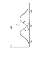
- valve lift law in a given cylinder can be that in Figure 2: the exhaust valve 3 follows the curve E; the valve intake 2 follows curve A while the specific valve follows curve E ', i.e. it opens at the same time as the valve exhaust but only closes when the intake valve closes closed. This makes it possible to obtain the cylinder to cylinder transfer according to the invention.
- the transfer means comprises a common conduit 5 which opens out in each of the specific holes 4.
- the transfer tube (s) 5 can be thermally insulated, using a ceramic 8 for example. She can also be heated by specific means 8 '. So the gases that pass through transfer tubing 5 do not lose or even gain calories when they arrive in the cylinder. Self-ignition is like this improved since we know that the temperature of the recycled gases is a important parameter, which promotes self-ignition.
- FIG. 3 shows schematically another embodiment of the invention which differs from that of FIG. 1 by the addition of a tube 9 which opens into the common tubing 5.
- a valve 10 is preferably disposed in the tubing 9, near its outlet in the tubing common 5.
- valve 4 At partial load, the operation is that explained above.
- the lift profile of valve 4 can be that of valve intake (curve A in Figure 2) with the means 10 in position opening: this ensures optimum filling of the cylinders.
- valve 4 can also, at full load, be similar to that of the exhaust valve (curve E in Figure 2), with the means 10 open in order to ensure optimum emptying of the engine.
- each valve 4 is used at full load either as intake or as exhaust. This characteristic therefore improves combustion during this operating phase.
- the means 10 is closed so that we end up with an operation such as described in relation to Figure 1.
- medium 10 is a completely optional addition to the embodiment of Figure 1 because it essentially allows improve operation at full load.
Landscapes
- Engineering & Computer Science (AREA)
- Chemical & Material Sciences (AREA)
- Combustion & Propulsion (AREA)
- Mechanical Engineering (AREA)
- General Engineering & Computer Science (AREA)
- Output Control And Ontrol Of Special Type Engine (AREA)
- Exhaust-Gas Circulating Devices (AREA)
- Combustion Methods Of Internal-Combustion Engines (AREA)
- Control Of Throttle Valves Provided In The Intake System Or In The Exhaust System (AREA)
- Valve Device For Special Equipments (AREA)
Claims (14)
- Verbrennungsverfahren eines 4-Takt-Motors durch geregelte Selbstzündung mit mehreren Zylindern (1 ), von denen ein jeder wenigstens ein erstes Einlassmittel (2) und wenigstens ein erstes Auslassmittel (3) hat, dadurch gekennzeichnet, dass es während des Teillastbetriebs darin besteht,a. über wenigstens eine spezifische Öffnung (4) jedes Zylinders und eine geeignete Transferleitung (5) Auslassgase von einem Zylinder in Auslassphase gegen einen anderen Zylinder in Einlassphase zu überführen,b. das Öffnen der spezifischen Öffnung (4) gleichzeitig wie das Öffnen des ersten Auslassmittels (3) vorzunehmen und diese Öffnung gleichzeitig mit dem Schließen des ersten Einlassmittels (2) zu schließen.
- Verfahren nach Anspruch 1, dadurch gekennzeichnet, dass es im übrigen darin besteht, die Verteilung des Durchsatzes der Auslassgase zwischen dem ersten Auslassmittel (3) und dem spezifischen Mittel (4) zu regeln.
- Verfahren nach einem der vorhergehenden Ansprüche, dadurch gekennzeichnet, dass es darin besteht, thermisch die in dieses geeignete Transfermittel transferierten Auslassgase zu isolieren und/oder wieder zu erwärmen.
- Verfahren nach einem der vorhergehenden Ansprüche, dadurch gekennzeichnet, dass man eine gemeinsame Leitung (5) für den Transfer der Auslassgase verwendet.
- Verfahren nach Anspruch 4, dadurch gekennzeichnet, dass bei Voll- und Überlast man die gemeinsame Leitung (5) und wenigstens gewisse der spezifischen Öffnungen (4) verwendet, um eine Charge einzulassen oder um zu veranlassen, dass Auslassgase abgezogen werden.
- Verfahren nach einem der Ansprüche 1 bis 3, dadurch gekennzeichnet, dass man für den Transfer der Auslassgase von Zylinder zu Zylinder eine Anordnung von Leitungen verwendet, welche die Zylinder zu je zwei verbinden.
- 4-Takt-Brennkraftmaschine, die mit geregelter Selbstzündung arbeitet und mehrere Zylinder (1) umfasst, von denen ein jeder wenigstens ein erstes Einlassmittel (2) und wenigstens ein erstes Auslassmittel (3) hat, dadurch gekennzeichnet, dass jeder Zylinder (1 ) im übrigen wenigstens ein spezifisches Mittel (4) umfasst, das zum Durchgang der Auslassgase von einem Zylinder in Auslassphase zu einem anderen Zylinder in Einlassphase bestimmt ist sowie ein Mittel (5) zum zugeordneten Transfer während des Teillastbetriebes umfasst und dass das spezifische Mittel (4) gleichzeitig mit der Öffnung des ersten Auslassmittels (3) offen ist und gleichzeitig mit dem Schließen des ersten Einlassmittels (2) geschlossen ist.
- Brennkraftmaschine nach Anspruch 7, dadurch gekennzeichnet, dass sie im übrigen ein Mittel zur thermischen Isolierung (8) und/oder zur Erwärmung (8') dieses Transfermittels umfasst.
- Brennkraftmaschine nach einem der Ansprüche 7 oder 8, dadurch gekennzeichnet, dass sie im übrigen ein Mittel (6, 7) zur Verteilung der Auslassgase zwischen dem ersten Auslassmittel (3) und dem spezifischen Mittel (4) bei Teillast umfasst.
- Brennkraftmaschine nach Anspruch 9, dadurch gekennzeichnet, dass das Verteilermittel für die Gase ein erstes Ventilmittel (6) umfasst, das benachbart dem ersten Auslassmittel (3) angeordnet ist.
- Brennkraftmaschine nach einem der Ansprüche 9 oder 10, dadurch gekennzeichnet, dass dieses Verteilermittel für die Gase ein zweites Ventilmittel (7) umfasst, das benachbart dem spezifischen Mittel für den Durchsatz der Gase (4) angeordnet ist.
- Brennkraftmaschine nach einem der Ansprüche 7 bis 11, dadurch gekennzeichnet, dass dieses Transfermittel eine gemeinsame Leitung (5) umfasst, die in jede der spezifischen Öffnungen (4) mündet.
- Brennkraftmaschine nach Anspruch 12, dadurch gekennzeichnet, dass diese gemeinsame Leitung (5) im übrigen eine Öffnung umfasst, in welche eine Leitung (9) mündet, die mit einem Mittel (10) zur Steuerung des Durchsatzes der Gase ausgestattet ist.
- Brennkraftmaschine nach einem der Ansprüche 7 bis 11, dadurch gekennzeichnet, dass dieses Transfermittel eine Anordnung von Leitungen umfasst, welche die Zylinder paarweise verbindet.
Applications Claiming Priority (2)
| Application Number | Priority Date | Filing Date | Title |
|---|---|---|---|
| FR9805925A FR2777947B1 (fr) | 1998-04-27 | 1998-04-27 | Procede de combustion par auto-allumage controle et moteur 4 temps associe avec conduit de transfert entre cylindres et soupape dediee |
| FR9805925 | 1998-04-27 |
Publications (2)
| Publication Number | Publication Date |
|---|---|
| EP0953745A1 EP0953745A1 (de) | 1999-11-03 |
| EP0953745B1 true EP0953745B1 (de) | 2003-10-15 |
Family
ID=9526229
Family Applications (1)
| Application Number | Title | Priority Date | Filing Date |
|---|---|---|---|
| EP99400895A Expired - Lifetime EP0953745B1 (de) | 1998-04-27 | 1999-04-13 | Überwachtes Selbstzündungsverbrennungsverfahren und zugehörige 4-Takt Brennkraftmaschine mit Transferleitung zwischen Zylinder und Ventil dafür |
Country Status (5)
| Country | Link |
|---|---|
| US (2) | US6178933B1 (de) |
| EP (1) | EP0953745B1 (de) |
| JP (1) | JPH11343887A (de) |
| DE (1) | DE69912019T2 (de) |
| FR (1) | FR2777947B1 (de) |
Families Citing this family (28)
| Publication number | Priority date | Publication date | Assignee | Title |
|---|---|---|---|---|
| DE19854461C1 (de) * | 1998-11-25 | 2000-03-09 | Daimler Chrysler Ag | Verbrennungsmotor, insbesondere Verbrennungsmotor für Fahrzeuge, mit einer Abgasrückführung |
| DE10009180C2 (de) * | 2000-02-26 | 2002-04-25 | Daimler Chrysler Ag | Verfahren zur Erzeugung eines homogenen Gemischs für selbstzündende Brennkraftmaschinen und zur Steuerung des Verbrennungsprozesses |
| DE10197229T5 (de) | 2001-04-09 | 2004-04-22 | Daihatsu Motor Co., Ltd., Ikeda | Mehrzylinder-Verbrennungsmotor |
| GB0115812D0 (en) * | 2001-06-28 | 2001-08-22 | Ford Global Tech Inc | Engine with controlled auto-ignition |
| US7182050B2 (en) * | 2002-01-31 | 2007-02-27 | Mazda Motor Corporation | Control device for spark-ignition engine |
| JP3956783B2 (ja) * | 2002-07-02 | 2007-08-08 | マツダ株式会社 | 火花点火式エンジンの制御装置 |
| JP3846393B2 (ja) * | 2002-09-30 | 2006-11-15 | マツダ株式会社 | 火花点火式エンジンの制御装置 |
| WO2004033888A2 (en) * | 2002-10-04 | 2004-04-22 | Honeywell International Inc. | Internal combustion engine system |
| US6758195B1 (en) * | 2002-11-26 | 2004-07-06 | Daimlerchrysler Corporation | System and method for fast exhaust gas recirculation in a combustion chamber |
| US6968825B2 (en) * | 2003-06-06 | 2005-11-29 | Mazda Motor Corporation | Control device for spark-ignition engine |
| US20040261774A1 (en) * | 2003-06-25 | 2004-12-30 | Eft Neil Wallace | Gas-assisted internal combustion engine |
| FR2866388B1 (fr) * | 2004-02-18 | 2009-05-29 | Renault Sas | Systeme de recirculation des gaz d'echappement d'un moteur a combustion interne |
| NZ531314A (en) | 2004-02-23 | 2006-10-27 | Shuttleworth Axial Motor Compa | Recirculation system for motor |
| SE531208C8 (de) * | 2004-03-31 | 2009-02-17 | ||
| JP3994990B2 (ja) * | 2004-07-21 | 2007-10-24 | 株式会社豊田中央研究所 | 燃料噴射装置 |
| WO2006043502A1 (ja) * | 2004-10-20 | 2006-04-27 | Koichi Hatamura | エンジン |
| JP4434056B2 (ja) * | 2005-03-25 | 2010-03-17 | 株式会社豊田自動織機 | 予混合圧縮自着火機関 |
| DE102006014996A1 (de) * | 2006-03-31 | 2007-10-04 | Robert Bosch Gmbh | Verfahren zum Betrieb einer Brennkraftmaschine |
| US7559317B2 (en) * | 2006-04-24 | 2009-07-14 | Barnett Joel Robinson | Internal combustion engine with single-port holding tank for elevated expansion ratio |
| JP2008169818A (ja) * | 2007-01-15 | 2008-07-24 | Yamaha Motor Co Ltd | 4サイクル内燃機関及び車両 |
| US7765994B2 (en) * | 2007-07-12 | 2010-08-03 | Ford Global Technologies, Llc | Cylinder charge temperature control for an internal combustion engine |
| EP2065586A1 (de) * | 2007-11-29 | 2009-06-03 | Perkins Engines Company Limited | Verbesserte Belüftung für einen Verbrennungsmotor |
| GB0806110D0 (en) * | 2008-04-04 | 2008-05-14 | Ma Thomas T H | Method for supplying boosted EGR in IC engine |
| FR2938880A1 (fr) * | 2008-11-21 | 2010-05-28 | Peugeot Citroen Automobiles Sa | Moteur a recirculation de gaz d'echappement et vehicule comprenant le moteur |
| GB2473481B (en) * | 2009-09-14 | 2015-06-17 | Univ Brunel | Method for supplying EGR in an IC engine |
| US20110061633A1 (en) * | 2009-09-16 | 2011-03-17 | Barnett Joel Robinson | Internal combustion engine having intake manifold combined with holding tank |
| US8146572B2 (en) * | 2009-12-21 | 2012-04-03 | Chrysler Group Llc | Cooled exhaust gas recirculation system with cylinder-level control |
| WO2018113930A1 (en) * | 2016-12-20 | 2018-06-28 | Volvo Truck Corporation | A method for controlling an internal combustion engine |
Citations (1)
| Publication number | Priority date | Publication date | Assignee | Title |
|---|---|---|---|---|
| DE3903474A1 (de) * | 1988-02-25 | 1989-09-07 | Avl Verbrennungskraft Messtech | Verfahren zum betrieb einer brennkraftmaschine |
Family Cites Families (17)
| Publication number | Priority date | Publication date | Assignee | Title |
|---|---|---|---|---|
| FR2078819A5 (de) * | 1970-02-19 | 1971-11-05 | British Leyland Motor Corp | |
| US3789807A (en) | 1972-06-19 | 1974-02-05 | J Pinkerton | Dual combustion process for an internal combustion engine |
| US3785355A (en) * | 1973-03-02 | 1974-01-15 | Gen Motors Corp | Engine with internal charge dilution and method |
| US4041910A (en) * | 1975-04-02 | 1977-08-16 | The United States Of America As Represented By The Administrator Of The National Aeronautics And Space Administration | Combustion engine |
| JPS5552049Y2 (de) * | 1976-01-31 | 1980-12-03 | ||
| US4159700A (en) * | 1976-10-18 | 1979-07-03 | Mccrum William H | Internal combustion compound engines |
| JPS5390505A (en) * | 1977-01-20 | 1978-08-09 | Isuzu Motors Ltd | Exhaust gas purifier for internal combustion engine having chamber |
| JPS5392017A (en) * | 1977-01-24 | 1978-08-12 | Isuzu Motors Ltd | Exhaust circulation device for internal combustion engine with by-chamber |
| DE2740045A1 (de) * | 1977-09-06 | 1979-03-15 | Bayerische Motoren Werke Ag | Verfahren zur teillast-steuerung von brennkraftmaschinen |
| JPS5846667B2 (ja) * | 1977-12-02 | 1983-10-18 | トヨタ自動車株式会社 | 多気筒内燃機関の排気ガス再循環装置 |
| JPS54116512A (en) * | 1978-03-02 | 1979-09-10 | Toyota Motor Corp | Internal combustion engine with reservoirs |
| US4282845A (en) | 1979-03-21 | 1981-08-11 | Toyota Jidosha Kogyo Kabushiki Kaisha | Internal combustion engine with exhaust gas accumulation chamber |
| DE3125647A1 (de) * | 1981-06-30 | 1983-01-13 | Robert Bosch Gmbh, 7000 Stuttgart | "brennkraftmaschine mit mehreren zylindern" |
| BE1000774A5 (fr) * | 1987-07-30 | 1989-04-04 | Schmitz Gerhard | Moteur a combustion interne a six temps. |
| JPH0658094B2 (ja) * | 1989-10-31 | 1994-08-03 | いすゞ自動車株式会社 | アルコールエンジンの再燃焼制御装置 |
| DE4036537C1 (en) * | 1990-11-16 | 1991-11-07 | Artur 7437 Westerheim De Krause | IC engine toxics reduction system - involves mixing off-gas from previous cycle to fresh air content |
| US5970944A (en) * | 1997-01-21 | 1999-10-26 | Isuzu Ceramics Research Institute Co., Ltd. | Combustion chamber structure in engines |
-
1998
- 1998-04-27 FR FR9805925A patent/FR2777947B1/fr not_active Expired - Fee Related
-
1999
- 1999-04-13 DE DE69912019T patent/DE69912019T2/de not_active Expired - Fee Related
- 1999-04-13 EP EP99400895A patent/EP0953745B1/de not_active Expired - Lifetime
- 1999-04-26 US US09/299,083 patent/US6178933B1/en not_active Expired - Fee Related
- 1999-04-26 US US09/299,085 patent/US6427644B1/en not_active Expired - Fee Related
- 1999-04-27 JP JP11120181A patent/JPH11343887A/ja active Pending
Patent Citations (1)
| Publication number | Priority date | Publication date | Assignee | Title |
|---|---|---|---|---|
| DE3903474A1 (de) * | 1988-02-25 | 1989-09-07 | Avl Verbrennungskraft Messtech | Verfahren zum betrieb einer brennkraftmaschine |
Also Published As
| Publication number | Publication date |
|---|---|
| US6427644B1 (en) | 2002-08-06 |
| FR2777947B1 (fr) | 2000-11-17 |
| FR2777947A1 (fr) | 1999-10-29 |
| DE69912019T2 (de) | 2004-04-29 |
| JPH11343887A (ja) | 1999-12-14 |
| DE69912019D1 (de) | 2003-11-20 |
| US6178933B1 (en) | 2001-01-30 |
| EP0953745A1 (de) | 1999-11-03 |
Similar Documents
| Publication | Publication Date | Title |
|---|---|---|
| EP0953745B1 (de) | Überwachtes Selbstzündungsverbrennungsverfahren und zugehörige 4-Takt Brennkraftmaschine mit Transferleitung zwischen Zylinder und Ventil dafür | |
| EP0863301B1 (de) | Verfahren zur Steuerung von Selbstzündung in einem Viertaktmotor | |
| EP1096118B1 (de) | Überwachtes Selbstzündungsverbrennungsverfahren und Viertaktbrennkraftmaschine mit Transferleitungen zwischen Auslass-und Einlassleitung | |
| EP2083155B1 (de) | Verfahren zur Spülung der verbrannten Abgase mit doppeltem Einlassventilhub eines Verbrennungsmotors mit Aufladung und Direkteinspritzung, insbesondere vom Dieseltyp | |
| FR2768180A1 (fr) | Procede de fonctionnement d'un moteur 4 temps, en auto-allumage controle | |
| EP1914409B1 (de) | Brennkraftmaschinesteuerverfahren und Brennkraftmaschine zur Durchführung des Verfahrens | |
| EP0953744B1 (de) | Überwachtes Selbstzündungsverbrennungsverfahren und zugehörige 4-Takt Brennkraftmaschine mit Restgasspeichervolumen und Ventil dafür | |
| EP1195505B1 (de) | Verfahren zur Steuerung der Selbstzündung in einem Viertaktmotor | |
| EP2354499B1 (de) | Verfahren zur Spülung der verbrannten Abgase eines Verbrennungsmotors mit Aufladung und Direkteinspritzung in Teillastbetrieb. | |
| EP1726805B1 (de) | Verfahren zur Steuerung der Spülung eines insbesondere aufgeladenen Motors mit Saugroheinspritzung und ein ein solches Verfahren verwendender Motor | |
| FR2744170A1 (fr) | Moteur diesel a quatre temps suralimente par turbocompresseur avec variation du calage des cames | |
| EP1790841A1 (de) | Verfahren zur Kontrolle der Zuschaltung und/oder Hemmung mindestens eins desaktivierten Zylinders eines Verbrennungsmotors | |
| WO2013190198A1 (fr) | Groupe moteur avec ligne de recirculation | |
| FR2835882A1 (fr) | Moteur a combustion interne, notamment a essence, equipe d'un turbocompresseur et d'une distribution variable | |
| FR2868481A1 (fr) | Procede de controle de la recirculation des gaz d'echappement d'un moteur suralimente a combustion interne et moteur utilisant un tel procede | |
| WO2014001667A1 (fr) | Groupe moteur avec ligne de recirculation | |
| FR2914366A1 (fr) | Procede de controle du fonctionnement d'un moteur a combustion interne en mode de combustion a autoallumage controle et moteur utilisant un tel procede | |
| WO2001051786A1 (fr) | Procede et dispositif pour ameliorer le fonctionnement a bas regime des moteurs thermiques suralimentes | |
| FR2867517A1 (fr) | Procede optimise de recirculation de gaz d'echappement pour moteur thermique, et moteur mettant en oeuvre ledit procede | |
| FR2933450A1 (fr) | Procede pour faciliter la vaporisation d'un carburant pour un moteur a combustion interne a injection directe, notamment de type diesel | |
| FR2883331A1 (fr) | Procede de commande d'un moteur a allumage par compression pour realiser une recirculation interne des gaz | |
| EP2273086A1 (de) | Verfahren zur Kontrolle der Zuleitung zu einem aufgeladenen Verbrennungsmotor, das eine Spüloperation der verbrannten Gase einschließt | |
| FR2904049A1 (fr) | Moteur thermique ayant deux conduits d'admission dont l'un est utilise pour balayer la chambre de combustion, module de gestion d'un tel moteur thermique et procede de gestion d'un moteur thermique |
Legal Events
| Date | Code | Title | Description |
|---|---|---|---|
| PUAI | Public reference made under article 153(3) epc to a published international application that has entered the european phase |
Free format text: ORIGINAL CODE: 0009012 |
|
| AK | Designated contracting states |
Kind code of ref document: A1 Designated state(s): DE GB IT NL SE |
|
| AX | Request for extension of the european patent |
Free format text: AL;LT;LV;MK;RO;SI |
|
| 17P | Request for examination filed |
Effective date: 20000503 |
|
| AKX | Designation fees paid |
Free format text: DE GB IT NL SE |
|
| 17Q | First examination report despatched |
Effective date: 20020226 |
|
| GRAH | Despatch of communication of intention to grant a patent |
Free format text: ORIGINAL CODE: EPIDOS IGRA |
|
| GRAS | Grant fee paid |
Free format text: ORIGINAL CODE: EPIDOSNIGR3 |
|
| GRAA | (expected) grant |
Free format text: ORIGINAL CODE: 0009210 |
|
| AK | Designated contracting states |
Kind code of ref document: B1 Designated state(s): DE GB IT NL SE |
|
| PG25 | Lapsed in a contracting state [announced via postgrant information from national office to epo] |
Ref country code: NL Free format text: LAPSE BECAUSE OF FAILURE TO SUBMIT A TRANSLATION OF THE DESCRIPTION OR TO PAY THE FEE WITHIN THE PRESCRIBED TIME-LIMIT Effective date: 20031015 Ref country code: GB Free format text: LAPSE BECAUSE OF FAILURE TO SUBMIT A TRANSLATION OF THE DESCRIPTION OR TO PAY THE FEE WITHIN THE PRESCRIBED TIME-LIMIT Effective date: 20031015 |
|
| REG | Reference to a national code |
Ref country code: GB Ref legal event code: FG4D Free format text: NOT ENGLISH |
|
| REF | Corresponds to: |
Ref document number: 69912019 Country of ref document: DE Date of ref document: 20031120 Kind code of ref document: P |
|
| PG25 | Lapsed in a contracting state [announced via postgrant information from national office to epo] |
Ref country code: SE Free format text: LAPSE BECAUSE OF FAILURE TO SUBMIT A TRANSLATION OF THE DESCRIPTION OR TO PAY THE FEE WITHIN THE PRESCRIBED TIME-LIMIT Effective date: 20040115 |
|
| NLV1 | Nl: lapsed or annulled due to failure to fulfill the requirements of art. 29p and 29m of the patents act | ||
| GBV | Gb: ep patent (uk) treated as always having been void in accordance with gb section 77(7)/1977 [no translation filed] |
Effective date: 20031015 |
|
| PLBE | No opposition filed within time limit |
Free format text: ORIGINAL CODE: 0009261 |
|
| STAA | Information on the status of an ep patent application or granted ep patent |
Free format text: STATUS: NO OPPOSITION FILED WITHIN TIME LIMIT |
|
| 26N | No opposition filed |
Effective date: 20040716 |
|
| PGFP | Annual fee paid to national office [announced via postgrant information from national office to epo] |
Ref country code: DE Payment date: 20080423 Year of fee payment: 10 |
|
| PGFP | Annual fee paid to national office [announced via postgrant information from national office to epo] |
Ref country code: IT Payment date: 20080421 Year of fee payment: 10 |
|
| PG25 | Lapsed in a contracting state [announced via postgrant information from national office to epo] |
Ref country code: DE Free format text: LAPSE BECAUSE OF NON-PAYMENT OF DUE FEES Effective date: 20091103 |
|
| PG25 | Lapsed in a contracting state [announced via postgrant information from national office to epo] |
Ref country code: IT Free format text: LAPSE BECAUSE OF NON-PAYMENT OF DUE FEES Effective date: 20090413 |