EP0953542A2 - Filling valve for a filling machine - Google Patents
Filling valve for a filling machine Download PDFInfo
- Publication number
- EP0953542A2 EP0953542A2 EP99105206A EP99105206A EP0953542A2 EP 0953542 A2 EP0953542 A2 EP 0953542A2 EP 99105206 A EP99105206 A EP 99105206A EP 99105206 A EP99105206 A EP 99105206A EP 0953542 A2 EP0953542 A2 EP 0953542A2
- Authority
- EP
- European Patent Office
- Prior art keywords
- gas
- filling
- valve
- channel
- pressure
- Prior art date
- Legal status (The legal status is an assumption and is not a legal conclusion. Google has not performed a legal analysis and makes no representation as to the accuracy of the status listed.)
- Granted
Links
Images


Classifications
-
- B—PERFORMING OPERATIONS; TRANSPORTING
- B67—OPENING, CLOSING OR CLEANING BOTTLES, JARS OR SIMILAR CONTAINERS; LIQUID HANDLING
- B67C—CLEANING, FILLING WITH LIQUIDS OR SEMILIQUIDS, OR EMPTYING, OF BOTTLES, JARS, CANS, CASKS, BARRELS, OR SIMILAR CONTAINERS, NOT OTHERWISE PROVIDED FOR; FUNNELS
- B67C3/00—Bottling liquids or semiliquids; Filling jars or cans with liquids or semiliquids using bottling or like apparatus; Filling casks or barrels with liquids or semiliquids
- B67C3/02—Bottling liquids or semiliquids; Filling jars or cans with liquids or semiliquids using bottling or like apparatus
- B67C3/06—Bottling liquids or semiliquids; Filling jars or cans with liquids or semiliquids using bottling or like apparatus using counterpressure, i.e. filling while the container is under pressure
- B67C3/10—Bottling liquids or semiliquids; Filling jars or cans with liquids or semiliquids using bottling or like apparatus using counterpressure, i.e. filling while the container is under pressure preliminary filling with inert gases, e.g. carbon dioxide
-
- B—PERFORMING OPERATIONS; TRANSPORTING
- B67—OPENING, CLOSING OR CLEANING BOTTLES, JARS OR SIMILAR CONTAINERS; LIQUID HANDLING
- B67C—CLEANING, FILLING WITH LIQUIDS OR SEMILIQUIDS, OR EMPTYING, OF BOTTLES, JARS, CANS, CASKS, BARRELS, OR SIMILAR CONTAINERS, NOT OTHERWISE PROVIDED FOR; FUNNELS
- B67C3/00—Bottling liquids or semiliquids; Filling jars or cans with liquids or semiliquids using bottling or like apparatus; Filling casks or barrels with liquids or semiliquids
- B67C3/02—Bottling liquids or semiliquids; Filling jars or cans with liquids or semiliquids using bottling or like apparatus
- B67C3/06—Bottling liquids or semiliquids; Filling jars or cans with liquids or semiliquids using bottling or like apparatus using counterpressure, i.e. filling while the container is under pressure
- B67C3/12—Pressure-control devices
-
- B—PERFORMING OPERATIONS; TRANSPORTING
- B67—OPENING, CLOSING OR CLEANING BOTTLES, JARS OR SIMILAR CONTAINERS; LIQUID HANDLING
- B67C—CLEANING, FILLING WITH LIQUIDS OR SEMILIQUIDS, OR EMPTYING, OF BOTTLES, JARS, CANS, CASKS, BARRELS, OR SIMILAR CONTAINERS, NOT OTHERWISE PROVIDED FOR; FUNNELS
- B67C3/00—Bottling liquids or semiliquids; Filling jars or cans with liquids or semiliquids using bottling or like apparatus; Filling casks or barrels with liquids or semiliquids
- B67C3/02—Bottling liquids or semiliquids; Filling jars or cans with liquids or semiliquids using bottling or like apparatus
- B67C3/22—Details
- B67C3/26—Filling-heads; Means for engaging filling-heads with bottle necks
- B67C3/2614—Filling-heads; Means for engaging filling-heads with bottle necks specially adapted for counter-pressure filling
- B67C3/2625—Filling-heads; Means for engaging filling-heads with bottle necks specially adapted for counter-pressure filling the liquid valve being opened automatically when a given counter-pressure is obtained in the container to be filled
- B67C3/2628—Filling-heads; Means for engaging filling-heads with bottle necks specially adapted for counter-pressure filling the liquid valve being opened automatically when a given counter-pressure is obtained in the container to be filled and the filling operation stopping when the liquid rises to a level at which it closes a vent opening
-
- B—PERFORMING OPERATIONS; TRANSPORTING
- B67—OPENING, CLOSING OR CLEANING BOTTLES, JARS OR SIMILAR CONTAINERS; LIQUID HANDLING
- B67C—CLEANING, FILLING WITH LIQUIDS OR SEMILIQUIDS, OR EMPTYING, OF BOTTLES, JARS, CANS, CASKS, BARRELS, OR SIMILAR CONTAINERS, NOT OTHERWISE PROVIDED FOR; FUNNELS
- B67C3/00—Bottling liquids or semiliquids; Filling jars or cans with liquids or semiliquids using bottling or like apparatus; Filling casks or barrels with liquids or semiliquids
- B67C3/02—Bottling liquids or semiliquids; Filling jars or cans with liquids or semiliquids using bottling or like apparatus
- B67C3/06—Bottling liquids or semiliquids; Filling jars or cans with liquids or semiliquids using bottling or like apparatus using counterpressure, i.e. filling while the container is under pressure
- B67C3/08—Bottling liquids or semiliquids; Filling jars or cans with liquids or semiliquids using bottling or like apparatus using counterpressure, i.e. filling while the container is under pressure and subsequently lowering the counterpressure
Definitions
- the invention relates to a single-chamber filling system. Filling systems of this type are in different designs known.
- the object of the invention is to demonstrate a filling system which is simplified constructive training a fill level adjustment via Trinox in particular reliably enabled.
- the span gas valve or its valve body also forms the Trinox valve. This results in a simplified and particularly reliable Education.
- an element reducing the gas flow for example provided in the form of a throttle or nozzle.
- This will in conjunction with the Special design of the gas valve ensures that the Trinox pressure in the filled Container (bottle) largely independent of fluctuations in gas pressure in the Trinox channel is.
- 1 is a ring bowl of a mechanical single-chamber filling system, or a mechanical single-chamber filling machine of all-round design.
- the ring bowl 1 is in a known manner part of the revolving around the vertical machine axis Rotors of the filling machine.
- the interior 2 of the Filling kettle 1 filled with the liquid filling material up to a predetermined level N see above that in the ring bowl 1 or in the bowl interior 2 one of the liquid contents occupied liquid space 2 'and above the level N a gas space 2' ' result of an inert gas, for example a CO2 gas with a predetermined Filling pressure picks up.
- an inert gas for example a CO2 gas with a predetermined Filling pressure picks up.
- a liquid channel 9 is formed in the housing 6 and extends above via a passage 10 communicates with the liquid space 2 'and on the underside of the housing 6 an annular discharge opening concentrically surrounding a return gas pipe 11 12 forms for the liquid filling material.
- a return gas pipe 11 12 forms for the liquid filling material.
- valve body 14 forming the filling or liquid valve 13 arranged, which in Figure 1 in its lower, the liquid valve 13 blocking Position is shown to open the liquid valve 13 in the direction of Valve axis VA moved up and moved down to close again is controlled in a known manner by a mechanical control element 15, the pinion 15 'with not shown control knobs one with the rotor is not circumferential control curve cooperates and via a control curve 15 '' on the Schaff 14 'acts.
- Valve needle 19 is formed, which extends through the mouth 17 into the interior of the Gas channels 16 stretched in and with their lower, free end with one there formed valve seat 16 'cooperates.
- the valve needle 19 is in the direction of the axis VA and thus in the axial direction of the gas channel 16 from which the gas channel 16 is blocked Position for opening the span gas and Trinox valve 18 can be raised, controlled through the mechanical control element 15.
- the valve needle 19 is still through it Dead weight, possibly also supported by a spring, not shown, in your that Tension gas and Trinox valve 18 biased locking position as follows is explained in more detail.
- channels 20 and 21 formed, of which the channel 20 at one end to the bottom of the Ring bowl 1 provided and common to all filling elements 3 Vacuum channel 22 is connected, which in turn with a not shown Vacuum or vacuum source is connected.
- the other end of the channel 20 is on an input of a mechanical control valve device 23 connected for each filling element 3 is provided separately on its housing 6.
- the control valve device 23 is an embodiment of a rotary slide valve is formed, which by means of a control lever 23 'by a not shown stationary control curve is controllable.
- a throttle 24 and a are in series in the channel 20 Valve 25 arranged.
- the latter acts on the one hand as a check valve in such a way that it only opens and in for a gas flow towards the vacuum channel 22 blocks in the opposite direction.
- the valve 25 also acts as Pressure relief valve, which closes when the pressure in channel 20 at the the side of the valve 25 facing away from the vacuum channel 22 below a lower one Pressure threshold (relief pressure) falls.
- the pressure threshold is adjustable.
- the channel 21 is connected at one end to a Trinox channel 26 which is connected to the underside of the ring bowl 1 as a common for all filling elements 3 Ring channel is formed.
- the other end of the channel 21 stands with a second one Input of the control valve 23 in connection.
- the Trinox channel 26 contains in a manner known per se Inert gas, for example CO2 gas, with a gas pressure that is above the filling pressure in the Gas space 2 '', i.e. in the Trinox channel 26 is e.g. a pressure is adjusted that by approx. 1.0 - 2.0 bar above the filling pressure in the gas space 2 ''.
- a third channel 28 is provided, which has one end with the Liquid channel 9 in the flow direction after the liquid valve 13 in connection stands and with its other end with a third connection of the control valve 23 connected is. In the control valve 23 is still a leading to the atmosphere Relief channel 29 is provided.
- the control valve 23 has e.g. at least four switch positions, namely a first Switch position in which all channels 20, 21 and 28 on control valve 23 are closed are, a second switching position in which the channel 20 is connected to the channel 28 and the channel 21 is closed and a third switching position in which the channel 20 closed on the control valve 23 and the channel 21 is connected to the channel 28. In a fourth switching position of the control valve, the channels 20 and 21 are closed, but the channel 28 connected to the channel 29 via the control valve.
- FIG. 2 shows a filling system which differs from the Filling system of Figure 1 essentially differs only in that instead of Vacuum channel a return gas channel 31 is provided, which in turn on the bottom of the ring bowl 1 as a common for all filling elements 3 ring channel is trained. Furthermore, in the embodiment of FIG. 2, the valve 25 is in the channel 20 omitted.
- a filling method is, for example, with the following Process steps possible:
- the filling valve 13 When the filling valve 13 is closed, it is in the sealing position with the filling element 3 located bottle 4 by connecting the channel 28 to the channel 20 via the Control valve 23 of the interior of the bottle 4 evacuated to approximately 90% vacuum.
- the channel 28 is reconnected to the channel 20 via the control valve 23, whereby the bottle is evacuated again to approx. 90% vacuum.
- the filling valve 13 is closed mechanically. As stated above, a pressure is regulated in the Trinox channel 26 which is approximately 1.0-2.0 bar above the filling pressure in the gas space 2 ′′.
- the span gas and Trinox valve 18 is now due to the pressure in the channel 16 in its open position.
- the channels 21 and 28 are via the control valve 23 connected so that from the Trinox channel 26 a limited by the nozzle 27 Gas flow can flow into the bottle 4 or in the bottle neck 1.
- In the bottle 4 there is an overpressure above the filling level there, which results from the Filling pressure in the ring bowl 1, from the weight or closing force of the valve needle 19th (Pressure threshold of the span gas and Trinox valve 18) and from the via the nozzle 27 incoming gas flow.
- This Trinox pressure in bottle 4 is through appropriate dimensioning of the cross section of the nozzle 27 and the closing force the valve needle 19 is set so that in the bottle 4 above the end 11 ' standing contents over the gas channel 16 gently and without any noteworthy Alarm, especially without significant foam and splash formation in the interior 2 of the ring bowl 1 is pushed back. Because of the 27th limited gas flow arises between the end 11 'and the product level in the Bottle 4 is a constant and reproducible gas gap. This allows Achieve filling level accuracies that are far above those of known filling systems.
- Trinox channel 26 is fed with CO2, then by the gas flow flowing into the interior 2 via the gas channel 16
- the atmosphere in the gas space 2 '' is constantly enriched with CO2.
- the gas expanding in the gas channel 16 can between the above-mentioned gas gap the end 11 'and the level in the bottle 4 without any noteworthy
- the surface of the product is disturbed via the bottle neck and channels 28 and 20 flow out.
- the filling material in the bottle 4 is disturbed by this in the gas channel 16 Expanding gas does not take place, in contrast to known ones Filling systems in which the end 11 'of the gas pipe 11 in the filling material at the end of the filling is immersed.
- the Pre-relief pressure set so that gas bubbles from the drink quickly and without a foam formation disturbing the filling process rises on the surface.
- the channel 28 is connected to the channel 29 via the control valve 23.
- the channels 20 and 21 are closed on the control valve 23.
- Via a nozzle provided in the channel 29 30 then the residual pressure is released to atmospheric pressure. Because of the previous one With these residual loads, pre-relief does not result in any significant spray losses.
- Valve 25 can be set so that it is only slightly above atmospheric pressure (e.g. about 0.5 bar). In this case, the residual relief can be dispensed with.
- the bottle 4 is only evacuated once, i.e. at first Evacuation and rinsing the bottle is dispensed with.
- the system is particularly suitable for filling bottom and top-fermented beers 6.0g CO2 / Ltr., From wheat beers to 9.0gr CO2 / Ltr. and oxygen sensitive Soft drinks.
- a method is possible which differs from the method described above in that the method steps Evacuate bottle 4 "as well Bottle 4 with intermediate CO2 rinsing "is omitted. Furthermore, the method step is the method step with the system of FIG Prestressing the bottle 4 "upstream of the following process step:
- the one contains predetermined or regulated CO2 pressure, which for example the corresponds to half the filling pressure.
- This partial prestressing creates in the respective Bottle 4 has an atmosphere with a high CO2 content.
- This CO2 atmosphere improved if CO2 is also used in the subsequent Trinox step, whereby the proportion of CO2 in the atmosphere in the gas space 2 '' and ultimately also the proportion of CO2 in the pre-relief channel 31 can be improved.
- Partial pre-tensioning to a medium pressure level will result in excessive Atomizing liquid particles during the subsequent tempering from the Ring kettle avoided. These atomized particles may form Release germs for the CO2 bound in the product, which leads to an uncontrolled Foaming could result in the subsequent relief.
- the regulated pressure relief takes place in the method with the system of FIG. 2 not via valve 25 into vacuum channel 22, but via that in channel 20 provided nozzle 24 in the return gas or pre-relief channel 31, in which, as above executed, the predetermined pre-relief pressure is set or adjusted, and although with the filling valve 13 closed and connected via the control valve 23 Channels 28 and 20.
- the Pre-relief pressure and the pressure change (by appropriate dimensioning the nozzle 24) optimally adjusted to the product to be filled, so that it is too no disturbances caused by the contents (foam formation, release of CO2 etc.) comes.
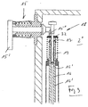
- FIG. 3 again shows the upper end of the shaft 14 'in an enlarged representation. and the span gas and Trinox valve 18 formed there with the valve needle 19.
- the valve needle 19 is provided in the upper end of the shaft 14 ' Disc 32 floating freely, i.e. slidable in the direction of the vertical axis VA intended.
- the disc 32 is used in a known manner in cooperation with the Control element 15 or its control curve 15 ′′ for closing the liquid valve 13.
- the valve needle 19 can thus be depressurized inside the bottle 4 attached to the filling element 3, whereby the lower end of the valve needle 19 the valve seat formed in the gas channel 16 16 'releases and thereby opens the span gas and Trinox valve 18.
- the here at Opening necessary pressure or pressure threshold result from the Mass weight of the valve needle 19. This opening pressure can also by a spring, not shown, can be increased or adjusted if necessary.
- the special feature is the double function of the valve needle 19 both as Tension gas as well as Tronix valve needle.
- the span gas and Trinox valve 18 results in Connection to the nozzle 27 provided in the channel 21 also regulates the Trinox pressure in the bottle neck of the bottle 4 attached to the filling element 3, in particular also in the form that pressure fluctuations in the Trinox channel 26 hardly occur affect the Trinox pressure in the bottle neck, i.e. the pressure in the bottle 4 is after opening the Trinox channel essentially as described above depending on the closing force or the pressure threshold of the clamping gas and Trinox valve 18 and the dimensioning of the nozzle 27 or from the latter Nozzle flowing into the bottle neck.
- the nozzle 27 and the closing force of the span gas or Trinox valve 18, i.e. the weight of the closing needle 19 are so set that the Trinox pressure formed in the bottle is just sufficient to Push excess product gently back into the interior 2.
- the pressure of the Pre-relief in the vacuum channel 22 can be set so low that a subsequent residual relief is no longer necessary.
Abstract
Description
Die Erfindung bezieht sich auf ein Einkammerfüllsystem. Füllsysteme dieser Art sind in unterschiedlichsten Ausführungen bekannt.The invention relates to a single-chamber filling system. Filling systems of this type are in different designs known.
Aufgabe der Erfindung ist es, ein Füllsystem aufzuzeigen, welches bei vereinfachter konstruktiver Ausbildung eine Füllhöheneinstellung über Trinox in besonders zuverlässiger Weise ermöglicht.The object of the invention is to demonstrate a filling system which is simplified constructive training a fill level adjustment via Trinox in particular reliably enabled.
Zur Lösung dieser Aufgabe ist ein Füllsystem entsprechend dem Patentanspruch 1 ausgebildet.To solve this problem is a filling system according to claim 1 educated.
Bei der Erfindung bildet das Spanngas-Ventil bzw. dessen Ventilkörper zugleich das Trinox-Ventil. Hierdurch ergibt sich eine vereinfachte und besonders betriebssichere Ausbildung.In the invention, the span gas valve or its valve body also forms the Trinox valve. This results in a simplified and particularly reliable Education.
Bei der bevorzugten Ausführungsform der Erfindung ist im ersten Gasweg, über den der Innenraum des Behälters nach dem Füllende und nach dem Schließen des Füll- oder Flüssigkeitsventil mit dem Trinox-Druck beaufschlagt wird, um die Füllhöhe einzustellen und überschüssiges Füllgut durch das Rückgasrohr in den Flüssigkeitsraum bzw. Kessel zurückzudrücken, ein den Gasfluß reduzierendes Element, beispielsweise in Form einer Drossel oder Düse vorgesehen. Hierdurch wird in Verbindung mit der speziellen Ausbildung des Spanngasventils erreicht, daß der Trinox-Druck im gefüllten Behälter (Flasche) weitestgehend unabhängig von Schwankungen des Gasdruckes im Trinox-Kanal ist.In the preferred embodiment of the invention in the first gas path via which the Interior of the container after the end of filling and after closing the filling or Liquid valve with the Trinox pressure is applied to the fill level adjust and excess filling through the return gas pipe into the liquid space or to push the boiler back, an element reducing the gas flow, for example provided in the form of a throttle or nozzle. This will in conjunction with the Special design of the gas valve ensures that the Trinox pressure in the filled Container (bottle) largely independent of fluctuations in gas pressure in the Trinox channel is.
Weiterbildungen der Erfindung sind Gegenstand der Unteransprüche. Die Erfindung wird im Folgenden anhand der Figuren an Ausführungsbeispielen näher erläutert. Es zeigen:
- Fig. 1
- in vereinfachter Darstellung und im Vertikalschnitt eines der Füllelemente einer Füllmaschine umlaufender Bauart bei einer ersten Ausführungsform der Erfindung;
- Fig. 2
- eine Darstellung wie
Figur 1, jedoch bei einer weiteren, möglichen Ausführungsform der Erfindung; - Fig. 3
- in vergrößerter Teildarstellung das Spanngas- und Trinox-Ventil.
- Fig. 1
- in a simplified representation and in vertical section of one of the filling elements of a rotating type of filling machine in a first embodiment of the invention;
- Fig. 2
- a representation like Figure 1, but in a further possible embodiment of the invention;
- Fig. 3
- in an enlarged partial view the span gas and Trinox valve.
In den Figuren ist 1 ein Ringkessels eines mechanischen Einkammer-Füllsystems, bzw.
einer mechanischen Einkammer-Füllmaschine umlaufender Bauart. Der Ringkessel 1 ist
in bekannter Weise Bestandteil des um die vertikale Maschinenachse umlaufenden
Rotors der Füllmaschine. Beim Betrieb der Füllmaschine ist der Innenraum 2 des
Füllkessels 1 bis zu einem vorgegebenen Niveau N mit dem flüssigen Füllgut gefüllt, so
daß sich im Ringkessel 1 bzw. im Kessel-Innenraum 2 ein vom flüssigen Füllgut
eingenommener Flüssigkeitsraum 2' und oberhalb des Niveaus N ein Gasraum 2''
ergeben, der ein Inertgas, beispielsweise ein CO2-Gas mit einem vorgegebenen
Fülldruck aufnimmt.In the figures, 1 is a ring bowl of a mechanical single-chamber filling system, or
a mechanical single-chamber filling machine of all-round design. The
An der Unterseite des Ringkessels 2 sind in gleichmäßigen Winkelabständen um die
Maschinenachse verteilt Füllelemente 3 vorgesehen, die jeweils mit einem nicht
dargestellten Flaschenträger eine Füllstelle bilden, und zwar zum Füllen der Flaschen 4,
die hierfür mit ihrer Flaschenmündung 5 durch den jeweiligen Flaschenträger in
Dichtlage gegen das Füllelement 3 bzw. gegen eine an der Unterseite des Gehäuses 6
des Füllelementes 3 im Bereich einer Zentriereinrichtung 7 gebildeten Ringdichtung 8
angepreßt sind.At the bottom of the
Im Gehäuse 6 ist ein Flüssigkeitskanal 9 ausgebildet, der oben über einen Durchlaß 10
mit dem Flüssigkeitsraum 2' in Verbindung steht und an der Unterseite des Gehäuses 6
eine ein Rückgasrohr 11 konzentrisch umschließende kreisringförmige Abgabeöffnung
12 für das flüssige Füllgut bildet. Bei in Dichtlage mit dem Füllelement 3 befindlicher
Flasche 4 steht deren Innenraum somit nach außen hin abgedichtet über die
Abgabeöffnung 12 mit dem unteren Ende des Flüssigkeitskanals 9 in Verbindung. Im
Flüssigkeitskanal 9 ist ein das Füll- oder Flüssigkeitsventil 13 bildender Ventilkörper 14
angeordnet, der in der Figur 1 in seiner unteren, das Flüssigkeitsventil 13 sperrenden
Stellung dargestellt ist, sich zum Öffnen des Flüssigkeitsventils 13 in Richtung der
Ventilachse VA nach oben bewegt und zum erneuten Schließen nach unten bewegt
wird, und zwar in bekannter Weise gesteuert durch ein mechanisches Steuerelement
15, dessen Ritzel 15' mit nicht dargestellten Steuernoppen einer mit dem Rotor nicht
umlaufenden Steuerkurve zusammenwirkt und der über eine Steuerkurve 15'' auf den
Schaff 14' einwirkt.A
Der Innenraum des Gasrohres 11, welches mit einer vorgegebenen Länge über die
Unterseite des Füllelementes 3 vorsteht und am unteren Ende 11' offen ist, setzt sich in
einem im Schaft 14' des Ventilkörpers 14 gebildeten Kanal fort, so daß ein Gaskanal 16
gebildet ist, der sich teilweise im Gasrohr 11 und teilweise im Schaft 14' erstreckt und
vom unteren Gasrohrende 11' bis in den Gasraum 2'' reicht, und zwar mit einer
dortigen Mündung 17, die im Gasraum 2'' deutlich über dem Niveau N liegt. Im
Bereich der Mündung 17 ist im Gaskanal 16 ein Spanngas- und Trinox-Ventil 18
vorgesehen, welches bei der dargestellten Ausführungsform im wesentlichen von einer
Ventilnadel 19 gebildet ist, die sich durch die Mündung 17 in das Innere des
Gaskanales 16 hineinerstreckt und mit ihrem unteren, freien Ende mit einem dort
gebildeten Ventilsitz 16' zusammenwirkt. Die Ventilnadel 19 ist in Richtung der Achse
VA und damit in Achsrichtung des Gaskanales 16 aus der den Gaskanal 16 sperrenden
Stellung zum Öffnen des Spanngas- und Trinox-Ventils 18 anhebbar, und zwar gesteuert
durch das mechanische Steuerelement 15. Die Ventilnadel 19 ist weiterhin durch ihr
Eigengewicht, ggf. auch noch unterstützt durch eine nicht dargestellte Feder in ihre das
Spanngas- und Trinox-Ventil 18 sperrende Stellung vorgespannt, wie dies nachstehend
noch näher erläutert wird.The interior of the
In dem Füllelement 3 und dabei teilweise im Gehäuse 6 sind u.a. die Kanäle 20 und 21
ausgebildet, von denen der Kanal 20 mit einem Ende an einen an der Unterseite des
Ringkessels 1 vorgesehenen und für sämtliche Füllelemente 3 gemeinsamen
Vakuumkanal 22 angeschlossen ist, der seinerseits mit einer nicht dargestellten
Vakuum- oder Unterdruckquelle verbunden ist. Das andere Ende des Kanales 20 ist an
einen Eingang einer mechanische Steuer-Ventileinrichtung 23 angeschlossen, die für
jedes Füllelement 3 gesondert an dessen Gehäuse 6 vorgesehen. Bei der dargestellten
Ausführungsform ist die Steuer-Ventileinrichtung 23 von einem Drehschieberventil
gebildet ist, welches mittels eines Steuer-Hebels 23' durch eine nicht dargestellte
stationäre Steuerkurve steuerbar ist. Im Kanal 20 sind in Serie eine Drossel 24 sowie ein
Ventil 25 angeordnet. Letzteres wirkt einerseits als Rückschlagventil in der Weise, daß
es nur für einen Gasstrom in Richtung zum Vakuumkanals 22 öffnet und in
entgegengesetzter Richtung sperrt. Weiterhin wirkt das Ventil 25 zugleich auch als
Druckbegrenzungsventil, welches dann schließt, wenn der Druck im Kanal 20 an der
dem Vakuumkanal 22 abgewandten Seite des Ventils 25 unter einen unteren
Druckschwellwert (Entlastungsdruck) fällt. Der Druckschwellwert ist einstellbar.In the
Der Kanal 21 ist mit seinem einen Ende mit einem Trinox-Kanal 26 verbunden, der an
der Unterseite des Ringkessels 1 als ein für sämtliche Füllelemente 3 gemeinsamer
Ringkanal ausgebildet ist. Das andere Ende des Kanals 21 steht mit einem zweiten
Eingang des Steuerventils 23 in Verbindung. Im Kanal 21 ist weiterhin eine zweite
Drossel 27 verbunden. Der Trinox-Kanal 26 enthält in an sich bekannter Weise ein
Inertgas, beispielsweise CO2-Gas, mit einem Gasdruck, der über dem Fülldruck im
Gasraum 2'' liegt, d.h. im Trinoxkanal 26 ist z.B. ein Druck eingeregelt, der um ca. 1,0 -
2,0 bar über dem Fülldruck im Gasraum 2'' liegt.The
Weiterhin ist ein dritter Kanal 28 vorgesehen, der mit seinem einen Ende mit dem
Flüssigkeitskanal 9 in Strömungsrichtung nach dem Flüssigkeitsventil 13 in Verbindung
steht und mit seinem anderen Ende mit einem dritten Anschluß des Steuerventils 23
verbunden ist. In dem Steuerventil 23 ist weiterhin ein an die Atmosphäre führende
Entlastungskanal 29 vorgesehen.Furthermore, a
Das Steuerventil 23 besitzt z.B. wenigstens vier Schaltstellungen, und zwar eine erste
Schaltstellung, in der sämtliche Kanäle 20, 21 und 28 am Steuerventil 23 verschlossen
sind, eine zweite Schaltstellung in der der Kanal 20 mit dem Kanal 28 verbunden ist
und der Kanal 21 verschlossen ist sowie eine dritte Schaltstellung, in der der Kanal 20
am Steuerventil 23 verschlossen und der Kanal 21 mit dem Kanal 28 verbunden ist. In
einer vierten Schaltstellung des Steuerventils sind die Kanäle 20 und 21 verschlossen,
aber der Kanal 28 über das Steuerventil mit dem Kanal 29 verbunden.The
Die Figur 2 zeigt als weitere Ausführungsform ein Füllsystem, welches sich vom
Füllsystem der Figur 1 im wesentlichen nur dadurch unterscheidet, daß anstelle des
Vakuum-Kanals ein Rückgaskanal 31 vorgesehen ist, der wiederum an der Unterseite
des Ringkessels 1 als ein für sämtliche Füllelemente 3 gemeinsamer Ringkanal
ausgebildet ist. Weiterhin ist bei der Ausführung der Figur 2 das Ventil 25 im Kanal 20
entfallen.As a further embodiment, FIG. 2 shows a filling system which differs from the
Filling system of Figure 1 essentially differs only in that instead of
Vacuum channel a
Mit dem System der Figur 1 ist ein Füllverfahren beispielsweise mit folgenden Verfahrensschritten möglich:With the system of Figure 1, a filling method is, for example, with the following Process steps possible:
Bei geschlossenem Füllventil 13 wird die in Dichtlage mit dem Füllelement 3
befindliche Flasche 4 durch Verbinden des Kanales 28 mit dem Kanal 20 über das
Steuerventil 23 der Innenraum der Flasche 4 auf ca. 90% Vakuum evakuiert.When the
Bei geschlossenem Füllventil 13 und bei die Kanäle 20, 21 und 28 sperrendem
Steuerventil 23 wird das Spanngas- und Trinox-Ventil 18 mechanisch geöffnet, und zwar
gesteuert über das Ritzel 15'. In die Flasche 4 wird dadurch CO2 aus dem Gasraum 2''
über den Gaskanal 16 eingeleitet.With the
Bei geschlossenem Füllventil 13 und geschlossenem Spanngas- und Trinox-Ventil 18
wird über das Steuerventil 23 der Kanal 28 erneut mit dem Kanal 20 verbunden,
wodurch ein erneutes Evakuieren der Flasche auf ca. 90% Vakuum erfolgt.With the
Bei geschlossenem Füllventil 13 und durch das Steuerventil 23 geschlossenen Kanälen
20, 21 und 28 erfolgt ein erneutes mechanisches Öffnen des Spanngas- und Trinox-Ventiles
18, und zwar gesteuert über das Ritzel 15', wobei der Innenraum der Flasche 4
auf dem Fülldruck vorgespannt wird.With the
Sobald ein Druckausgleich zwischen dem Innenraum der Flasche 4 und dem Ringkessel
bzw. den dortigen Gasraum 2'' erfolgt ist, öffnet das Flüssigkeitsventil 13 aufgrund der
Feder-Vorspannung des Ventilkörpers 14 selbsttätig. Das Spanngas- und Trinox-Ventil
18 ist weiterhin mechanisch geöffnet. Die Kanäle 20, 21 und 28 sind durch das
Steuerventil 23 gesperrt.As soon as a pressure equalization between the interior of the
Sobald der Füllgutspiegel in der Flasche 4 das untere Ende 11' des Rückgasrohres 11
übersteigt, wird der Abfluß des vom Füllgut aus dem Innenraum der Flasche 4
verdrängten Gases über den Gaskanal 16 in den Gasraum 2'' unterbrochen. Hiermit
wird das weitere Zufließen des Füllgutes aus dem Flüssigkeitsraum 2' verhindert. Das
Spanngas- und Trinox-Ventil 18 befindet sich weiterhin in der geöffneten Stellung. Die
Kanäle 20, 21 und 28 sind am Steuerventil 23 gesperrt.As soon as the level in the
Das Füllventil 13 wird mechanisch geschlossen.
Wie oben ausgeführt, ist im Trinox-Kanal 26 ein Druck eingeregelt, der um ca. 1,0 - 2,0
bar über dem Fülldruck im Gasraum 2'' liegt.The filling
As stated above, a pressure is regulated in the
Das Spanngas- und Trinox-Ventil 18 befindet sich nun aufgrund des Druckes im Kanal
16 in seiner geöffneten Stellung. Die Kanäle 21 und 28 sind über das Steuerventil 23
verbunden, so daß aus dem Trinox-Kanal 26 ein durch die Düse 27 begrenzter
Gasstrom in die Flasche 4 bzw. in den Flaschenhals 1 fließen kann. In der Flasche 4
stellt sich oberhalb des dortigen Füllgutpegels ein Überdruck ein, der sich aus dem
Fülldruck im Ringkessel 1, aus der Gewichts- oder Schließkraft der Ventilnadel 19
(Druck-Schwellwert des Spanngas- und Trinox-Ventils 18) und aus dem über die Düse
27 zufließenden Gasstrom ableitet. Dieser Trinox-Druck in der Flasche 4 ist durch
entsprechende Dimensionierung des Querschnittes der Düse 27 und der Schließkraft
der Ventilnadel 19 so eingestellt, daß das in der Flasche 4 oberhalb des Endes 11'
stehende Füllgut über den Gaskanal 16 schonend und ohne nennenswerte
Beunruhigung, insbesondere auch ohne nennenswerte Schaum- und Spritzerbildung in
den Innenraum 2 des Ringkessels 1 zurückgedrückt wird. Wegen des über die Düse 27
begrenzten Gasstromes entsteht zwischen dem Ende 11' und dem Füllgutspiegel in der
Flasche 4 ein konstanter und reproduzierbarer Gasspalt. Hierdurch lassen sich
Füllhöhengenauigkeiten erreichen, die weit über denen bekannter Füllsysteme liegen.The span gas and
Wird der Trinox-Kanal 26, wie vorstehend beschrieben, mit CO2 gespeißt, so wird
durch den über den Gaskanal 16 dem Innenraum 2 zufließenden Gasstrom die
Atmosphäre im Gasraum 2'' ständig mit CO2 angereichert.If the
Bei geschlossenem Füllventil 13, bei geschlossenem Spanngas- und Trinox-Ventil 18
und bei über das Steuerventil 23 verbundenen Kanälen 20 und 28 erfolgt eine
druckgeregelte Vorentlastung. Hierfür ist am Ventil 25 (durch entsprechende Wahl der
Federkraft) der im Flaschenhals gewünschte Vorentlastungsdruck eingestellt. Die bei der
Vorentlastung aus der Flasche 4 entweichenden Gase werden über den Vakuumkanal
22 abgeführt. Der Druckabbau vom Fülldruck auf den Vorentlastungsdruck erfolgt
schonend, und zwar durch die Drosselung des Gasstromes über die Düse oder Drossel
24.With the filling
Das im Gaskanal 16 expandierende Gas kann über den erwähnten Gasspalt zwischen
dem Ende 11' und dem Füllgutspiegel in der Flasche 4 ohne nennenswerte
Beunruhigung der Füllgutoberfläche über den Flaschenhals und die Kanäle 28 und 20
abströmen. Eine Beunruhigung des Füllgutes in der Flasche 4 durch dieses im Gaskanal
16 expandierende Gas erfolgt somit nicht, und zwar im Gegensatz zu bekannten
Füllsystemen, bei denen am Füllende das Ende 11' des Gasrohres 11 im Füllgut
eingetaucht ist. In Abhängigkeit von dem jeweils abzufüllenden Füllgut ist der
Vorentlastungsdruck so eingestellt, daß Gasblasen aus dem Getränk schnell und ohne
eine den Füllprozeß störende Schaumbildung an der Oberfläche aufsteigen. The gas expanding in the
Bei geschlossenem Füllventil 13 und geschlossenem Spanngas- und Trinox-Ventil 18
wird über das Steuerventil 23 der Kanal 28 mit dem Kanal 29 verbunden. Die Kanäle 20
und 21 sind am Steuerventil 23 geschlossen. Über eine im Kanal 29 vorgesehene Düse
30 erfolgt dann das Restentlasten auf Atmosphärendruck. Wegen der vorausgegangenen
Vorentlastung entstehen bei diesen Restentlasten keine nennenswerte Abspritzverluste.With the filling
Bei bestimmten Füllgutarten, beispielsweise bei Bier, kann der Vorentlastungsdruck am
Ventil 25 so eingestellt werden, daß er nur geringfügig über dem Atmosphärendruck
liegt (z.B. etwa 0,5 Bar). In diesem Fall kann auf die Restentlastung verzichtet werden.With certain types of product, such as beer, the pre-relief pressure can be on
Eine weitere Modifikation des vorstehend beschriebenen Verfahrens besteht darin, daß
beispielsweise nur eine einmalige Evakuierung der Flasche 4 erfolgt, d.h. auf die erste
Evakuierung und das Zwischenspülen der Flasche verzichtet wird.Another modification of the method described above is that
For example, the
Das mit der Ausführungsform der Figur 1 mögliche, vorstehend beschriebene
Füllverfahren (Einkammer-Füllprinzip mit oder ohne Vorevakuierung, mit
druckgeregelter Vorentlastung in den Vakuumkanal 22, mit Höhenkorrektur durch
Trinox und Restentlastung in die Atmosphäre) eignet sich insbesondere zum Abfüllen
von Wein, Cooler-Getränke, Schaumwein, Sekt und Perlwein sowie CO2-haltiger
Spirituosen-Mischgetränke.The possible with the embodiment of Figure 1, described above
Filling process (single-chamber filling principle with or without pre-evacuation, with
pressure-controlled pre-relief in the
In der Ausführungsform mit doppelter Vorevakuierung (sauerstoffarme Abfüllung) eignet sich das System vor allem auch zum Abfüllen von unter- und obergärigen Bieren bis 6,0gr CO2/Ltr., von Weizenbieren bis 9,0gr CO2/Ltr. und sauerstoffempfindlichen Softdrinks.In the embodiment with double pre-evacuation (low-oxygen filling) is suitable the system is particularly suitable for filling bottom and top-fermented beers 6.0g CO2 / Ltr., From wheat beers to 9.0gr CO2 / Ltr. and oxygen sensitive Soft drinks.
Mit dem in der Figur 2 wiedergegebenen System ist beispielsweise ein Verfahren
möglich, welches sich von dem vorstehend beschriebenen Verfahren dadurch
unterscheidet, daß die Verfahrensschritte ![]()
![]()
Bei geschlossenem Füllventil 13 und bei über das Steuerventil 23 verbundenen Kanälen
20 und 28 erfolgt vor dem endgültigen Vorspannen der Flasche 4 aus dem Gasraum 2''
ein Teilvorspannen aus dem Rückgas- oder Vorentlastungskanal 31, der einen
vorgegebenen bzw. eingeregelten CO2-Druck enthält, welcher beispielsweise den
halben Fülldruck entspricht. Durch dieses Teilvorspannen entsteht in der jeweiligen
Flasche 4 eine Atmosphäre mit hohem CO2-Anteil. Diese CO2-Atmosphäre verbessert
sich, wenn in dem später folgenden Trinox-Schritt ebenfalls CO2 zum Einsatz kommt,
wodurch der Anteil an CO2 in der Atmosphäre im Gasraum 2'' und damit letztlich auch
der Anteil an CO2 im Vorentlastungskanal 31 verbessert werden.With the filling
Durch das Teilvorspannen auf ein mittleres Druckniveau wird ein übermäßiges Zerstäuben von Flüssigkeitspartikel beim anschließenden Vorspannen aus dem Ringkessel vermieden. Diese zerstäubten Partikel bilden unter Umständen Entbindungskeime für das im Füllgut gebundene CO2, was zu einer unkontrollierten Schaumbildung bei der späteren Entlastung führen könnte.Partial pre-tensioning to a medium pressure level will result in excessive Atomizing liquid particles during the subsequent tempering from the Ring kettle avoided. These atomized particles may form Release germs for the CO2 bound in the product, which leads to an uncontrolled Foaming could result in the subsequent relief.
Die Verfahrensschritte Vorspannen der Flasche aus dem Gasraum 2'', Füllen, Füllende, Füllventil mechanisch schließen und Trinox öffnen entsprechen dem vorstehend beschriebenen Verfahren.The process steps of prestressing the bottle from the gas space 2 '', filling, filling, Mechanically close the filling valve and open Trinox correspond to the above described method.
Die geregelte Druckentlastung erfolgt bei dem Verfahren mit dem System der Figur 2
nicht über das Ventil 25 in den Vakuumkanal 22, sondern über die im Kanal 20
vorgesehene Düse 24 in den Rückgas- oder Vorentlastungskanal 31, in dem, wie oben
ausgeführt, der vorgegebene Vorentlastungsdruck eingestellt bzw. eingeregelt ist, und
zwar bei geschlossenem Füllventil 13 und bei über das Steuerventil 23 verbundenen
Kanälen 28 und 20. Auch bei dieser druckgeregelten Vorentlastung sind der
Vorentlastungsdruck sowie die Durckänderung (durch entsprechende Dimensionierung
der Düse 24) auf das jeweils abzufüllende Füllgut optimal eingestellt, so daß es zu
keinen durch das Füllgut bedingten Störungen (Schaumbildung, Freisetzen von CO2
usw.) kommt.The regulated pressure relief takes place in the method with the system of FIG. 2
not via
Die Figur 3 zeigt nochmals in vergrößerter Darstellung das obere Ende des Schaftes 14'
und das dort gebildete Spanngas- und Trinox-Ventil 18 mit der Ventilnadel 19. Wie
dargestellt, ist die Ventilnadel 19 in der am oberen Ende des Schaftes 14' vorgesehenen
Scheibe 32 frei schwimmend, d.h. in Richtung der vertikalen Achse VA verschiebbar
vorgesehen. Die Scheibe 32 dient in bekannter Weise im Zusammenwirken mit dem
Steuerelement 15 bzw. dessen Steuerkurve 15'' zum Schließen des Flüssigkeitsventils
13. Bei geschlossenem Flüssigkeitsventil 13 kann somit die Ventilnadel 19 vom Druck
im Inneren der an das Füllelement 3 angesetzten Flasche 4 angehoben werden,
wodurch das untere Ende der Ventilnadel 19 den im Gaskanal 16 gebildeten Ventilsitz
16' freigibt und dadurch das Spanngas- und Trinox-Ventil 18 öffnet. Der hierbei zum
Öffnen notwendige Druck oder Druck-Schwellwert ergeben sich aus dem
Massengewicht der Ventilnadel 19. Dieser Öffnungsdruck kann auch zusätzlich durch
eine nicht dargestellte Feder erhöht bzw. eingestellt werden, sofern dies notwendig ist.FIG. 3 again shows the upper end of the shaft 14 'in an enlarged representation.
and the span gas and
Die Besonderheit besteht somit in der Doppelfunktion der Ventilnadel 19 sowohl als
Spanngas- als auch als Tronix-Ventilnadel.The special feature is the double function of the
Beim Spülen und/oder Vorspannen aus dem Gasraum 2'' wird die Nadel 19 durch das
Steuerelement 15 bzw. durch die an diesem Steuerelement gebildeten Steuerkurve 15''
mechanisch zum Öffnen des Spanngas- und Trinox-Ventils 18 angehoben.When flushing and / or prestressing from the
Mit der beschriebenen Ausbildung des Spanngas- und Trinox-Ventils 18 ergibt sich in
Verbindung mit der im Kanal 21 vorgesehenen Düse 27 auch eine Regelung des Trinox-Druckes
im Flaschenhals der am Füllelement 3 angesetzten Flasche 4, insbesondere
auch in der Form, daß sich Druckschwankungen im Trinox-Kanal 26 kaum noch auf
dem Trinox-Druck im Flaschenhals auswirken, d.h. der Druck in der Flasche 4 ist nach
dem Öffnen des Trinox-Kanals in der oben beschriebenen Weise im wesentlichen
abhängig von der Schließkraft bzw. dem Druck-Schwellwert des Spanngas- und
Trinoxventils 18 und von der Dimensionierung der Düse 27 bzw. von dem über diese
Düse in den Flaschenhals einströmenden Gasstrom. Die Düse 27 und die Schließkraft
des Spanngas- oder Trinoxventils 18, d.h. das Gewicht der Schließnadel 19 werden so
eingestellt, daß der in der Flasche gebildete Trinox-Druck gerade ausreicht, um
überschüssiges Produkt schonend in den Innenraum 2 zurückzuschieben.With the described configuration of the span gas and
Durch die Vorentlastung und möglicherweise auch Restentlastung in den Vakuumkanal
22 werden auch mikrobiologische Probleme vermieden, die sich bei einer Entlastung in
die Atmosphäre in unmittelbarer Nähe des jeweiligen Füllelementes 3 durch zersteubtes
Füllgut können ergeben. Speziell auch bei der Abfüllung von Bier kann der Druck der
Vorentlastung in den Vakuumkanal 22 so niedrig eingestellt werden, daß eine
nachfolgende Restentlastung nicht mehr notwendig ist. Due to the preliminary relief and possibly also residual relief in the
- 11
- RingkesselRing bowl
- 22nd
- KesselinnenraumBoiler interior
- 2'2 '
- FlüssigkeitsraumFluid space
- 2''2 ''
- GasraumGas space
- 33rd
- FüllelementFilling element
- 44th
- Flaschebottle
- 55
- FlaschenmündungBottle mouth
- 66
- Gehäusecasing
- 77
- ZentrierelementCentering element
- 88th
- RingdichtungRing seal
- 99
- FlüssigkeitskanalLiquid channel
- 1010th
- DurchlaßPassage
- 1111
- RückgasrohrReturn gas pipe
- 11'11 '
- EndeThe End
- 1212th
- AbgabeöffnungDelivery opening
- 1313
- Füll- oder FlüssigkeitsventilFilling or liquid valve
- 1414
- VentilkörperValve body
- 14'14 '
- VentilkörperschaftValve body
- 1515
- SteuerelementControl
- 15'15 '
- Ritzelpinion
- 15''15 ''
- SteuerkurveControl curve
- 1616
- GaskanalGas channel
- 16'16 '
- VentilsitzValve seat
- 1717th
- Mündungmuzzle
- 1818th
- Spanngas- und TrinoxventilTension gas and Trinox valve
- 1919th
- VentilnadelValve needle
- 20, 2120, 21
- Kanalchannel
- 2222
- VakuumkanalVacuum channel
- 2323
- SteuerventilControl valve
- 2424th
- Drossel throttle
- 2525th
- Rückschlag- und DruckregelventilCheck and pressure control valve
- 2626
- Trinox-KanalTrinox channel
- 2727
- Drosselthrottle
- 28, 2928, 29
- Kanalchannel
- 3030th
- Drosselthrottle
- 3131
- Rückgas- oder VorentlastungskanalReturn gas or pre-relief duct
- 3232
- Scheibedisc
Claims (14)
Applications Claiming Priority (2)
| Application Number | Priority Date | Filing Date | Title |
|---|---|---|---|
| DE19818761 | 1998-04-27 | ||
| DE19818761A DE19818761A1 (en) | 1998-04-27 | 1998-04-27 | Single-chamber filling system |
Publications (3)
| Publication Number | Publication Date |
|---|---|
| EP0953542A2 true EP0953542A2 (en) | 1999-11-03 |
| EP0953542A3 EP0953542A3 (en) | 2000-02-09 |
| EP0953542B1 EP0953542B1 (en) | 2003-12-17 |
Family
ID=7865920
Family Applications (1)
| Application Number | Title | Priority Date | Filing Date |
|---|---|---|---|
| EP99105206A Expired - Lifetime EP0953542B1 (en) | 1998-04-27 | 1999-03-12 | Filling valve for a filling machine |
Country Status (5)
| Country | Link |
|---|---|
| US (1) | US6213169B1 (en) |
| EP (1) | EP0953542B1 (en) |
| AT (1) | ATE256633T1 (en) |
| BR (1) | BR9902482A (en) |
| DE (2) | DE19818761A1 (en) |
Cited By (2)
| Publication number | Priority date | Publication date | Assignee | Title |
|---|---|---|---|---|
| WO2015004001A1 (en) * | 2013-07-09 | 2015-01-15 | Khs Gmbh | Filling system and method for the treatment of containers with a process gas |
| US9969603B2 (en) | 2013-07-09 | 2018-05-15 | Khs Gmbh | Filling system |
Families Citing this family (24)
| Publication number | Priority date | Publication date | Assignee | Title |
|---|---|---|---|---|
| JP4701542B2 (en) * | 2001-05-31 | 2011-06-15 | 澁谷工業株式会社 | Filling apparatus and filling method thereof |
| DE10259602A1 (en) * | 2002-12-19 | 2004-07-08 | Khs Maschinen- Und Anlagenbau Ag | Labeling machine for labeling containers |
| DE10359492B3 (en) * | 2003-12-13 | 2005-09-15 | Khs Maschinen- Und Anlagenbau Ag | Filling element for a filling machine |
| DE10359312B4 (en) * | 2003-12-17 | 2016-02-25 | Khs Gmbh | Filling machine for filling containers |
| DE20319789U1 (en) * | 2003-12-20 | 2004-02-26 | Khs Maschinen- Und Anlagenbau Ag | Filling machine with separate return gas duct |
| DE102004029788A1 (en) * | 2004-06-19 | 2006-01-12 | Khs Maschinen- Und Anlagenbau Ag | Device for labeling vessels |
| US7523771B2 (en) | 2005-10-04 | 2009-04-28 | Adcor Industries, Inc. | Filling valve apparatus for a beverage filling machine |
| ITVI20050310A1 (en) * | 2005-11-24 | 2007-05-25 | Gruppo Bertolaso Spa | PERFECT EQUIPMENT FOR FILLING CONTAINERS |
| DE102006017706A1 (en) * | 2006-04-15 | 2007-10-25 | Khs Ag | Filling elements and filling machine with a filling element |
| ITVI20070100A1 (en) * | 2007-04-03 | 2008-10-04 | Gruppo Bertolaso Spa | PERFECT EQUIPMENT FOR FILLING CONTAINERS |
| DE102007057285A1 (en) * | 2007-11-28 | 2009-06-04 | Krones Ag | Method for filling containers |
| DE102008030948A1 (en) * | 2008-07-02 | 2010-01-21 | Khs Ag | Filling system for filling bottles or similar containers and filling machine |
| DE102010047883A1 (en) * | 2010-10-11 | 2012-04-12 | Khs Gmbh | Method and filling system for volume and / or quantity-controlled filling of containers |
| ITBS20110036A1 (en) * | 2011-03-31 | 2012-10-01 | Corfill Internat S R L | FILLING VALVE FOR FOOD USE WITH FILLING LEVEL ADJUSTMENT SYSTEM AND ITS FILLING METHOD |
| KR101569603B1 (en) * | 2011-04-06 | 2015-11-16 | 미쯔비시 쥬우꼬오 쇼구힌호오소오기까이 가부시키가이샤 | Rotary-type filling machine and method for calculating filling quantity for rotary-type filling machine |
| CN102522223B (en) * | 2011-11-09 | 2013-10-30 | 南京大学 | Controllable filling method for vacuum filling |
| ITPD20120028A1 (en) * | 2012-02-07 | 2013-08-08 | Mbf Spa | FILLING MACHINE OF CONTAINERS WITH LIQUIDS, AND FILLING PROCEDURE OF CONTAINERS, IN PARTICULAR THROUGH THE FILLING MACHINE |
| ITTO20120117A1 (en) * | 2012-02-10 | 2013-08-11 | Agricola A Responsabilita Limitata Siglabile C S | VINIFICATION PROCEDURE OF SWEET WINES WITHOUT PRESERVATIVE USE |
| DE102013102616A1 (en) | 2013-03-14 | 2014-09-18 | Khs Gmbh | Method and filling system for filling containers |
| DE102013106756A1 (en) * | 2013-06-27 | 2014-12-31 | Khs Gmbh | Method and filling system for filling containers |
| DE102013108638A1 (en) * | 2013-08-09 | 2015-03-05 | Khs Gmbh | Method and system for rinsing containers |
| IT201600122730A1 (en) * | 2016-12-02 | 2018-06-02 | Co Mac Srl | Modular machine for filling bottles and cans |
| DE102018127592B4 (en) * | 2018-11-06 | 2020-07-16 | Khs Gmbh | Filling element, filling system and method for filling containers |
| CN110272006B (en) * | 2019-06-13 | 2024-03-08 | 江苏可奥熙光学材料科技有限公司 | Online filling device for optical resin monomer |
Citations (3)
| Publication number | Priority date | Publication date | Assignee | Title |
|---|---|---|---|---|
| GB2071629A (en) * | 1980-03-05 | 1981-09-23 | Seitz Werke Gmbh | Filling machine |
| EP0601514A1 (en) * | 1992-12-10 | 1994-06-15 | KHS Maschinen- und Anlagenbau Aktiengesellschaft | Filling machine, in particular for counter-pressure filling |
| DE9321223U1 (en) * | 1992-08-08 | 1996-09-12 | Mette Manfred | Counterpressure filling device for filling drinks containing CO¶2¶ into bottles or other containers |
Family Cites Families (2)
| Publication number | Priority date | Publication date | Assignee | Title |
|---|---|---|---|---|
| DE3825093C2 (en) * | 1988-07-23 | 1994-01-13 | Kronseder Maschf Krones | Method and device for filling bottles or the like in counterpressure filling machines |
| DE4213737A1 (en) * | 1991-10-17 | 1993-04-22 | Seitz Enzinger Noll Masch | METHOD FOR FILLING BOTTLES OR THE LIKE CONTAINERS WITH A LIQUID FILLING MATERIAL AND DEVICE FOR CARRYING OUT THIS METHOD |
-
1998
- 1998-04-27 DE DE19818761A patent/DE19818761A1/en not_active Withdrawn
-
1999
- 1999-03-12 DE DE59908059T patent/DE59908059D1/en not_active Expired - Lifetime
- 1999-03-12 EP EP99105206A patent/EP0953542B1/en not_active Expired - Lifetime
- 1999-03-12 AT AT99105206T patent/ATE256633T1/en active
- 1999-04-22 BR BR9902482A patent/BR9902482A/en not_active IP Right Cessation
- 1999-04-26 US US09/299,497 patent/US6213169B1/en not_active Expired - Lifetime
Patent Citations (3)
| Publication number | Priority date | Publication date | Assignee | Title |
|---|---|---|---|---|
| GB2071629A (en) * | 1980-03-05 | 1981-09-23 | Seitz Werke Gmbh | Filling machine |
| DE9321223U1 (en) * | 1992-08-08 | 1996-09-12 | Mette Manfred | Counterpressure filling device for filling drinks containing CO¶2¶ into bottles or other containers |
| EP0601514A1 (en) * | 1992-12-10 | 1994-06-15 | KHS Maschinen- und Anlagenbau Aktiengesellschaft | Filling machine, in particular for counter-pressure filling |
Cited By (3)
| Publication number | Priority date | Publication date | Assignee | Title |
|---|---|---|---|---|
| WO2015004001A1 (en) * | 2013-07-09 | 2015-01-15 | Khs Gmbh | Filling system and method for the treatment of containers with a process gas |
| US9809436B2 (en) | 2013-07-09 | 2017-11-07 | Khs Gmbh | Filling system and method for the treatment of containers with a process gas |
| US9969603B2 (en) | 2013-07-09 | 2018-05-15 | Khs Gmbh | Filling system |
Also Published As
| Publication number | Publication date |
|---|---|
| BR9902482A (en) | 2000-03-21 |
| ATE256633T1 (en) | 2004-01-15 |
| EP0953542A3 (en) | 2000-02-09 |
| US6213169B1 (en) | 2001-04-10 |
| DE19818761A1 (en) | 1999-10-28 |
| DE59908059D1 (en) | 2004-01-29 |
| EP0953542B1 (en) | 2003-12-17 |
Similar Documents
| Publication | Publication Date | Title |
|---|---|---|
| EP0953542B1 (en) | Filling valve for a filling machine | |
| EP1692071B1 (en) | Filling element for a filling machine and filling machine provided with filling elements of this type | |
| EP1584601B1 (en) | Filling machine of the rotary type | |
| EP1204555B1 (en) | Method for the preservation of an opened drink bottle | |
| EP2996980B1 (en) | Filling system and filling machine for filling containers | |
| EP2307306B1 (en) | Filling system for filling bottles or similar containers, and filling machine | |
| DE3836489A1 (en) | METHOD AND DEVICE FOR FILLING BEVERAGE CAN | |
| DE102005003222A1 (en) | Device for filling containers has filler pipe with standpipe with valve body on outside and gas pipe on inside which are vertically movable independent of one another to form ring chamber opening downwards | |
| EP1216952B1 (en) | Filling machine | |
| DE3446501C2 (en) | ||
| EP2768762B1 (en) | Method and filling machine for filling bottles with a liquid filling material | |
| EP0588356B1 (en) | Filling divice for bottles or like containers | |
| DE102013103639A1 (en) | Filling element, filling system and method for filling containers | |
| DE1482649A1 (en) | Valve filling valve for bottling beverages, especially alcohol-free and sparkling beverages with a high pulp content | |
| DE4402980C1 (en) | Gravity bottle filling device for still and fizzy beverages | |
| DE2454888A1 (en) | BOTTLE FILLING MACHINE | |
| DE102016105552A1 (en) | Filling valve for filling a container with a filling product | |
| DE4342142C2 (en) | Device for filling bottles or similar containers with a liquid filling material | |
| DE2123865A1 (en) | Filling element | |
| EP0554690A1 (en) | Method for filling bottles or similar containers with a liquid product and apparatus for carrying-out this method | |
| DE2638749C3 (en) | Device for filling bottles with constant pressure | |
| DE102015113369A1 (en) | Method for filling cans or the like. Containers with a liquid product | |
| DE102013103418A1 (en) | Method and filling system for filling containers with a liquid product | |
| EP0416473B1 (en) | Filling head for counter pressure bottling machine | |
| DE102020110899A1 (en) | Method for filling containers |
Legal Events
| Date | Code | Title | Description |
|---|---|---|---|
| PUAI | Public reference made under article 153(3) epc to a published international application that has entered the european phase |
Free format text: ORIGINAL CODE: 0009012 |
|
| AK | Designated contracting states |
Kind code of ref document: A2 Designated state(s): AT BE DE FR IT NL |
|
| AX | Request for extension of the european patent |
Free format text: AL;LT;LV;MK;RO;SI |
|
| RTI1 | Title (correction) |
Free format text: FILLING VALVE FOR A FILLING MACHINE |
|
| PUAL | Search report despatched |
Free format text: ORIGINAL CODE: 0009013 |
|
| RIN1 | Information on inventor provided before grant (corrected) |
Inventor name: KRULITSCH, DIETER-RUDOLF Inventor name: CLUESSERATH, LUDWIG |
|
| AK | Designated contracting states |
Kind code of ref document: A3 Designated state(s): AT BE CH CY DE DK ES FI FR GB GR IE IT LI LU MC NL PT SE |
|
| AX | Request for extension of the european patent |
Free format text: AL;LT;LV;MK;RO;SI |
|
| 17P | Request for examination filed |
Effective date: 20000308 |
|
| AKX | Designation fees paid |
Free format text: AT BE DE FR IT NL |
|
| 17Q | First examination report despatched |
Effective date: 20030310 |
|
| GRAH | Despatch of communication of intention to grant a patent |
Free format text: ORIGINAL CODE: EPIDOS IGRA |
|
| GRAS | Grant fee paid |
Free format text: ORIGINAL CODE: EPIDOSNIGR3 |
|
| GRAA | (expected) grant |
Free format text: ORIGINAL CODE: 0009210 |
|
| AK | Designated contracting states |
Kind code of ref document: B1 Designated state(s): AT BE DE FR IT NL |
|
| REF | Corresponds to: |
Ref document number: 59908059 Country of ref document: DE Date of ref document: 20040129 Kind code of ref document: P |
|
| ET | Fr: translation filed | ||
| PLBE | No opposition filed within time limit |
Free format text: ORIGINAL CODE: 0009261 |
|
| STAA | Information on the status of an ep patent application or granted ep patent |
Free format text: STATUS: NO OPPOSITION FILED WITHIN TIME LIMIT |
|
| 26N | No opposition filed |
Effective date: 20040920 |
|
| REG | Reference to a national code |
Ref country code: NL Ref legal event code: TD Effective date: 20111114 |
|
| REG | Reference to a national code |
Ref country code: FR Ref legal event code: CD Owner name: KHS GMBH Effective date: 20111122 Ref country code: FR Ref legal event code: CD Owner name: KHS GMBH Effective date: 20111121 |
|
| REG | Reference to a national code |
Ref country code: AT Ref legal event code: PC Ref document number: 256633 Country of ref document: AT Kind code of ref document: T Owner name: KHS GMBH, DE Effective date: 20111220 |
|
| BECN | Be: change of holder's name |
Owner name: KHS G.M.B.H. Effective date: 20120314 |
|
| REG | Reference to a national code |
Ref country code: FR Ref legal event code: PLFP Year of fee payment: 18 |
|
| PGFP | Annual fee paid to national office [announced via postgrant information from national office to epo] |
Ref country code: NL Payment date: 20160321 Year of fee payment: 18 |
|
| PGFP | Annual fee paid to national office [announced via postgrant information from national office to epo] |
Ref country code: BE Payment date: 20160321 Year of fee payment: 18 Ref country code: AT Payment date: 20160322 Year of fee payment: 18 Ref country code: FR Payment date: 20160321 Year of fee payment: 18 |
|
| PGFP | Annual fee paid to national office [announced via postgrant information from national office to epo] |
Ref country code: DE Payment date: 20160330 Year of fee payment: 18 |
|
| PGFP | Annual fee paid to national office [announced via postgrant information from national office to epo] |
Ref country code: IT Payment date: 20160324 Year of fee payment: 18 |
|
| REG | Reference to a national code |
Ref country code: DE Ref legal event code: R119 Ref document number: 59908059 Country of ref document: DE |
|
| REG | Reference to a national code |
Ref country code: NL Ref legal event code: MM Effective date: 20170401 |
|
| REG | Reference to a national code |
Ref country code: AT Ref legal event code: MM01 Ref document number: 256633 Country of ref document: AT Kind code of ref document: T Effective date: 20170312 |
|
| REG | Reference to a national code |
Ref country code: FR Ref legal event code: ST Effective date: 20171130 |
|
| PG25 | Lapsed in a contracting state [announced via postgrant information from national office to epo] |
Ref country code: AT Free format text: LAPSE BECAUSE OF NON-PAYMENT OF DUE FEES Effective date: 20170312 Ref country code: NL Free format text: LAPSE BECAUSE OF NON-PAYMENT OF DUE FEES Effective date: 20170401 Ref country code: FR Free format text: LAPSE BECAUSE OF NON-PAYMENT OF DUE FEES Effective date: 20170331 Ref country code: DE Free format text: LAPSE BECAUSE OF NON-PAYMENT OF DUE FEES Effective date: 20171003 |
|
| PG25 | Lapsed in a contracting state [announced via postgrant information from national office to epo] |
Ref country code: IT Free format text: LAPSE BECAUSE OF NON-PAYMENT OF DUE FEES Effective date: 20170312 |
|
| REG | Reference to a national code |
Ref country code: BE Ref legal event code: MM Effective date: 20170331 |
|
| PG25 | Lapsed in a contracting state [announced via postgrant information from national office to epo] |
Ref country code: BE Free format text: LAPSE BECAUSE OF NON-PAYMENT OF DUE FEES Effective date: 20170331 |