EP0953472A2 - Control system to maintain battery charge state in a hybrid vehicule - Google Patents
Control system to maintain battery charge state in a hybrid vehicule Download PDFInfo
- Publication number
- EP0953472A2 EP0953472A2 EP99108275A EP99108275A EP0953472A2 EP 0953472 A2 EP0953472 A2 EP 0953472A2 EP 99108275 A EP99108275 A EP 99108275A EP 99108275 A EP99108275 A EP 99108275A EP 0953472 A2 EP0953472 A2 EP 0953472A2
- Authority
- EP
- European Patent Office
- Prior art keywords
- current
- signals
- battery
- state
- charge
- Prior art date
- Legal status (The legal status is an assumption and is not a legal conclusion. Google has not performed a legal analysis and makes no representation as to the accuracy of the status listed.)
- Granted
Links
Images


Classifications
-
- H—ELECTRICITY
- H02—GENERATION; CONVERSION OR DISTRIBUTION OF ELECTRIC POWER
- H02J—ELECTRIC POWER NETWORKS; CIRCUIT ARRANGEMENTS OR SYSTEMS FOR SUPPLYING OR DISTRIBUTING ELECTRIC POWER; SYSTEMS FOR STORING ELECTRIC ENERGY
- H02J7/00—Circuit arrangements for charging or discharging batteries or for supplying loads from batteries
-
- B—PERFORMING OPERATIONS; TRANSPORTING
- B60—VEHICLES IN GENERAL
- B60K—ARRANGEMENT OR MOUNTING OF PROPULSION UNITS OR OF TRANSMISSIONS IN VEHICLES; ARRANGEMENT OR MOUNTING OF PLURAL DIVERSE PRIME-MOVERS IN VEHICLES; AUXILIARY DRIVES FOR VEHICLES; INSTRUMENTATION OR DASHBOARDS FOR VEHICLES; ARRANGEMENTS IN CONNECTION WITH COOLING, AIR INTAKE, GAS EXHAUST OR FUEL SUPPLY OF PROPULSION UNITS IN VEHICLES
- B60K6/00—Arrangement or mounting of plural diverse prime-movers for mutual or common propulsion, e.g. hybrid propulsion systems comprising electric motors and internal combustion engines
- B60K6/20—Arrangement or mounting of plural diverse prime-movers for mutual or common propulsion, e.g. hybrid propulsion systems comprising electric motors and internal combustion engines the prime-movers consisting of electric motors and internal combustion engines, e.g. HEVs
- B60K6/22—Arrangement or mounting of plural diverse prime-movers for mutual or common propulsion, e.g. hybrid propulsion systems comprising electric motors and internal combustion engines the prime-movers consisting of electric motors and internal combustion engines, e.g. HEVs characterised by apparatus, components or means specially adapted for HEVs
- B60K6/24—Arrangement or mounting of plural diverse prime-movers for mutual or common propulsion, e.g. hybrid propulsion systems comprising electric motors and internal combustion engines the prime-movers consisting of electric motors and internal combustion engines, e.g. HEVs characterised by apparatus, components or means specially adapted for HEVs characterised by the combustion engines
-
- B—PERFORMING OPERATIONS; TRANSPORTING
- B60—VEHICLES IN GENERAL
- B60W—CONJOINT CONTROL OF VEHICLE SUB-UNITS OF DIFFERENT TYPE OR DIFFERENT FUNCTION; CONTROL SYSTEMS SPECIALLY ADAPTED FOR HYBRID VEHICLES; ROAD VEHICLE DRIVE CONTROL SYSTEMS FOR PURPOSES NOT RELATED TO THE CONTROL OF A PARTICULAR SUB-UNIT
- B60W20/00—Control systems specially adapted for hybrid vehicles
- B60W20/10—Controlling the power contribution of each of the prime movers to meet required power demand
- B60W20/13—Controlling the power contribution of each of the prime movers to meet required power demand in order to stay within battery power input or output limits; in order to prevent overcharging or battery depletion
-
- B—PERFORMING OPERATIONS; TRANSPORTING
- B60—VEHICLES IN GENERAL
- B60K—ARRANGEMENT OR MOUNTING OF PROPULSION UNITS OR OF TRANSMISSIONS IN VEHICLES; ARRANGEMENT OR MOUNTING OF PLURAL DIVERSE PRIME-MOVERS IN VEHICLES; AUXILIARY DRIVES FOR VEHICLES; INSTRUMENTATION OR DASHBOARDS FOR VEHICLES; ARRANGEMENTS IN CONNECTION WITH COOLING, AIR INTAKE, GAS EXHAUST OR FUEL SUPPLY OF PROPULSION UNITS IN VEHICLES
- B60K6/00—Arrangement or mounting of plural diverse prime-movers for mutual or common propulsion, e.g. hybrid propulsion systems comprising electric motors and internal combustion engines
- B60K6/20—Arrangement or mounting of plural diverse prime-movers for mutual or common propulsion, e.g. hybrid propulsion systems comprising electric motors and internal combustion engines the prime-movers consisting of electric motors and internal combustion engines, e.g. HEVs
- B60K6/22—Arrangement or mounting of plural diverse prime-movers for mutual or common propulsion, e.g. hybrid propulsion systems comprising electric motors and internal combustion engines the prime-movers consisting of electric motors and internal combustion engines, e.g. HEVs characterised by apparatus, components or means specially adapted for HEVs
- B60K6/26—Arrangement or mounting of plural diverse prime-movers for mutual or common propulsion, e.g. hybrid propulsion systems comprising electric motors and internal combustion engines the prime-movers consisting of electric motors and internal combustion engines, e.g. HEVs characterised by apparatus, components or means specially adapted for HEVs characterised by the motors or the generators
-
- B—PERFORMING OPERATIONS; TRANSPORTING
- B60—VEHICLES IN GENERAL
- B60K—ARRANGEMENT OR MOUNTING OF PROPULSION UNITS OR OF TRANSMISSIONS IN VEHICLES; ARRANGEMENT OR MOUNTING OF PLURAL DIVERSE PRIME-MOVERS IN VEHICLES; AUXILIARY DRIVES FOR VEHICLES; INSTRUMENTATION OR DASHBOARDS FOR VEHICLES; ARRANGEMENTS IN CONNECTION WITH COOLING, AIR INTAKE, GAS EXHAUST OR FUEL SUPPLY OF PROPULSION UNITS IN VEHICLES
- B60K6/00—Arrangement or mounting of plural diverse prime-movers for mutual or common propulsion, e.g. hybrid propulsion systems comprising electric motors and internal combustion engines
- B60K6/20—Arrangement or mounting of plural diverse prime-movers for mutual or common propulsion, e.g. hybrid propulsion systems comprising electric motors and internal combustion engines the prime-movers consisting of electric motors and internal combustion engines, e.g. HEVs
- B60K6/22—Arrangement or mounting of plural diverse prime-movers for mutual or common propulsion, e.g. hybrid propulsion systems comprising electric motors and internal combustion engines the prime-movers consisting of electric motors and internal combustion engines, e.g. HEVs characterised by apparatus, components or means specially adapted for HEVs
- B60K6/28—Arrangement or mounting of plural diverse prime-movers for mutual or common propulsion, e.g. hybrid propulsion systems comprising electric motors and internal combustion engines the prime-movers consisting of electric motors and internal combustion engines, e.g. HEVs characterised by apparatus, components or means specially adapted for HEVs characterised by the electric energy storing means, e.g. batteries or capacitors
-
- B—PERFORMING OPERATIONS; TRANSPORTING
- B60—VEHICLES IN GENERAL
- B60K—ARRANGEMENT OR MOUNTING OF PROPULSION UNITS OR OF TRANSMISSIONS IN VEHICLES; ARRANGEMENT OR MOUNTING OF PLURAL DIVERSE PRIME-MOVERS IN VEHICLES; AUXILIARY DRIVES FOR VEHICLES; INSTRUMENTATION OR DASHBOARDS FOR VEHICLES; ARRANGEMENTS IN CONNECTION WITH COOLING, AIR INTAKE, GAS EXHAUST OR FUEL SUPPLY OF PROPULSION UNITS IN VEHICLES
- B60K6/00—Arrangement or mounting of plural diverse prime-movers for mutual or common propulsion, e.g. hybrid propulsion systems comprising electric motors and internal combustion engines
- B60K6/20—Arrangement or mounting of plural diverse prime-movers for mutual or common propulsion, e.g. hybrid propulsion systems comprising electric motors and internal combustion engines the prime-movers consisting of electric motors and internal combustion engines, e.g. HEVs
- B60K6/22—Arrangement or mounting of plural diverse prime-movers for mutual or common propulsion, e.g. hybrid propulsion systems comprising electric motors and internal combustion engines the prime-movers consisting of electric motors and internal combustion engines, e.g. HEVs characterised by apparatus, components or means specially adapted for HEVs
- B60K6/32—Arrangement or mounting of plural diverse prime-movers for mutual or common propulsion, e.g. hybrid propulsion systems comprising electric motors and internal combustion engines the prime-movers consisting of electric motors and internal combustion engines, e.g. HEVs characterised by apparatus, components or means specially adapted for HEVs characterised by the fuel cells
-
- B—PERFORMING OPERATIONS; TRANSPORTING
- B60—VEHICLES IN GENERAL
- B60K—ARRANGEMENT OR MOUNTING OF PROPULSION UNITS OR OF TRANSMISSIONS IN VEHICLES; ARRANGEMENT OR MOUNTING OF PLURAL DIVERSE PRIME-MOVERS IN VEHICLES; AUXILIARY DRIVES FOR VEHICLES; INSTRUMENTATION OR DASHBOARDS FOR VEHICLES; ARRANGEMENTS IN CONNECTION WITH COOLING, AIR INTAKE, GAS EXHAUST OR FUEL SUPPLY OF PROPULSION UNITS IN VEHICLES
- B60K6/00—Arrangement or mounting of plural diverse prime-movers for mutual or common propulsion, e.g. hybrid propulsion systems comprising electric motors and internal combustion engines
- B60K6/20—Arrangement or mounting of plural diverse prime-movers for mutual or common propulsion, e.g. hybrid propulsion systems comprising electric motors and internal combustion engines the prime-movers consisting of electric motors and internal combustion engines, e.g. HEVs
- B60K6/42—Arrangement or mounting of plural diverse prime-movers for mutual or common propulsion, e.g. hybrid propulsion systems comprising electric motors and internal combustion engines the prime-movers consisting of electric motors and internal combustion engines, e.g. HEVs characterised by the architecture of the hybrid electric vehicle
- B60K6/46—Series type
-
- B—PERFORMING OPERATIONS; TRANSPORTING
- B60—VEHICLES IN GENERAL
- B60L—PROPULSION OF ELECTRICALLY-PROPELLED VEHICLES; SUPPLYING ELECTRIC POWER FOR AUXILIARY EQUIPMENT OF ELECTRICALLY-PROPELLED VEHICLES; ELECTRODYNAMIC BRAKE SYSTEMS FOR VEHICLES IN GENERAL; MAGNETIC SUSPENSION OR LEVITATION FOR VEHICLES; MONITORING OPERATING VARIABLES OF ELECTRICALLY-PROPELLED VEHICLES; ELECTRIC SAFETY DEVICES FOR ELECTRICALLY-PROPELLED VEHICLES
- B60L58/00—Methods or circuit arrangements for monitoring or controlling batteries or fuel cells, specially adapted for electric vehicles
- B60L58/10—Methods or circuit arrangements for monitoring or controlling batteries or fuel cells, specially adapted for electric vehicles for monitoring or controlling batteries
-
- B—PERFORMING OPERATIONS; TRANSPORTING
- B60—VEHICLES IN GENERAL
- B60W—CONJOINT CONTROL OF VEHICLE SUB-UNITS OF DIFFERENT TYPE OR DIFFERENT FUNCTION; CONTROL SYSTEMS SPECIALLY ADAPTED FOR HYBRID VEHICLES; ROAD VEHICLE DRIVE CONTROL SYSTEMS FOR PURPOSES NOT RELATED TO THE CONTROL OF A PARTICULAR SUB-UNIT
- B60W10/00—Conjoint control of vehicle sub-units of different type or different function
- B60W10/04—Conjoint control of vehicle sub-units of different type or different function including control of propulsion units
- B60W10/06—Conjoint control of vehicle sub-units of different type or different function including control of propulsion units including control of combustion engines
-
- B—PERFORMING OPERATIONS; TRANSPORTING
- B60—VEHICLES IN GENERAL
- B60W—CONJOINT CONTROL OF VEHICLE SUB-UNITS OF DIFFERENT TYPE OR DIFFERENT FUNCTION; CONTROL SYSTEMS SPECIALLY ADAPTED FOR HYBRID VEHICLES; ROAD VEHICLE DRIVE CONTROL SYSTEMS FOR PURPOSES NOT RELATED TO THE CONTROL OF A PARTICULAR SUB-UNIT
- B60W10/00—Conjoint control of vehicle sub-units of different type or different function
- B60W10/04—Conjoint control of vehicle sub-units of different type or different function including control of propulsion units
- B60W10/08—Conjoint control of vehicle sub-units of different type or different function including control of propulsion units including control of electric propulsion units, e.g. motors or generators
-
- B—PERFORMING OPERATIONS; TRANSPORTING
- B60—VEHICLES IN GENERAL
- B60W—CONJOINT CONTROL OF VEHICLE SUB-UNITS OF DIFFERENT TYPE OR DIFFERENT FUNCTION; CONTROL SYSTEMS SPECIALLY ADAPTED FOR HYBRID VEHICLES; ROAD VEHICLE DRIVE CONTROL SYSTEMS FOR PURPOSES NOT RELATED TO THE CONTROL OF A PARTICULAR SUB-UNIT
- B60W10/00—Conjoint control of vehicle sub-units of different type or different function
- B60W10/24—Conjoint control of vehicle sub-units of different type or different function including control of energy storage means
- B60W10/26—Conjoint control of vehicle sub-units of different type or different function including control of energy storage means for electrical energy, e.g. batteries or capacitors
-
- B—PERFORMING OPERATIONS; TRANSPORTING
- B60—VEHICLES IN GENERAL
- B60W—CONJOINT CONTROL OF VEHICLE SUB-UNITS OF DIFFERENT TYPE OR DIFFERENT FUNCTION; CONTROL SYSTEMS SPECIALLY ADAPTED FOR HYBRID VEHICLES; ROAD VEHICLE DRIVE CONTROL SYSTEMS FOR PURPOSES NOT RELATED TO THE CONTROL OF A PARTICULAR SUB-UNIT
- B60W10/00—Conjoint control of vehicle sub-units of different type or different function
- B60W10/28—Conjoint control of vehicle sub-units of different type or different function including control of fuel cells
-
- B—PERFORMING OPERATIONS; TRANSPORTING
- B60—VEHICLES IN GENERAL
- B60W—CONJOINT CONTROL OF VEHICLE SUB-UNITS OF DIFFERENT TYPE OR DIFFERENT FUNCTION; CONTROL SYSTEMS SPECIALLY ADAPTED FOR HYBRID VEHICLES; ROAD VEHICLE DRIVE CONTROL SYSTEMS FOR PURPOSES NOT RELATED TO THE CONTROL OF A PARTICULAR SUB-UNIT
- B60W20/00—Control systems specially adapted for hybrid vehicles
-
- Y—GENERAL TAGGING OF NEW TECHNOLOGICAL DEVELOPMENTS; GENERAL TAGGING OF CROSS-SECTIONAL TECHNOLOGIES SPANNING OVER SEVERAL SECTIONS OF THE IPC; TECHNICAL SUBJECTS COVERED BY FORMER USPC CROSS-REFERENCE ART COLLECTIONS [XRACs] AND DIGESTS
- Y02—TECHNOLOGIES OR APPLICATIONS FOR MITIGATION OR ADAPTATION AGAINST CLIMATE CHANGE
- Y02T—CLIMATE CHANGE MITIGATION TECHNOLOGIES RELATED TO TRANSPORTATION
- Y02T10/00—Road transport of goods or passengers
- Y02T10/60—Other road transportation technologies with climate change mitigation effect
- Y02T10/62—Hybrid vehicles
-
- Y—GENERAL TAGGING OF NEW TECHNOLOGICAL DEVELOPMENTS; GENERAL TAGGING OF CROSS-SECTIONAL TECHNOLOGIES SPANNING OVER SEVERAL SECTIONS OF THE IPC; TECHNICAL SUBJECTS COVERED BY FORMER USPC CROSS-REFERENCE ART COLLECTIONS [XRACs] AND DIGESTS
- Y02—TECHNOLOGIES OR APPLICATIONS FOR MITIGATION OR ADAPTATION AGAINST CLIMATE CHANGE
- Y02T—CLIMATE CHANGE MITIGATION TECHNOLOGIES RELATED TO TRANSPORTATION
- Y02T10/00—Road transport of goods or passengers
- Y02T10/60—Other road transportation technologies with climate change mitigation effect
- Y02T10/70—Energy storage systems for electromobility, e.g. batteries
-
- Y—GENERAL TAGGING OF NEW TECHNOLOGICAL DEVELOPMENTS; GENERAL TAGGING OF CROSS-SECTIONAL TECHNOLOGIES SPANNING OVER SEVERAL SECTIONS OF THE IPC; TECHNICAL SUBJECTS COVERED BY FORMER USPC CROSS-REFERENCE ART COLLECTIONS [XRACs] AND DIGESTS
- Y02—TECHNOLOGIES OR APPLICATIONS FOR MITIGATION OR ADAPTATION AGAINST CLIMATE CHANGE
- Y02T—CLIMATE CHANGE MITIGATION TECHNOLOGIES RELATED TO TRANSPORTATION
- Y02T90/00—Enabling technologies or technologies with a potential or indirect contribution to GHG emissions mitigation
- Y02T90/40—Application of hydrogen technology to transportation, e.g. using fuel cells
-
- Y—GENERAL TAGGING OF NEW TECHNOLOGICAL DEVELOPMENTS; GENERAL TAGGING OF CROSS-SECTIONAL TECHNOLOGIES SPANNING OVER SEVERAL SECTIONS OF THE IPC; TECHNICAL SUBJECTS COVERED BY FORMER USPC CROSS-REFERENCE ART COLLECTIONS [XRACs] AND DIGESTS
- Y10—TECHNICAL SUBJECTS COVERED BY FORMER USPC
- Y10S—TECHNICAL SUBJECTS COVERED BY FORMER USPC CROSS-REFERENCE ART COLLECTIONS [XRACs] AND DIGESTS
- Y10S320/00—Electricity: battery or capacitor charging or discharging
- Y10S320/18—Indicator or display
- Y10S320/21—State of charge of battery
-
- Y—GENERAL TAGGING OF NEW TECHNOLOGICAL DEVELOPMENTS; GENERAL TAGGING OF CROSS-SECTIONAL TECHNOLOGIES SPANNING OVER SEVERAL SECTIONS OF THE IPC; TECHNICAL SUBJECTS COVERED BY FORMER USPC CROSS-REFERENCE ART COLLECTIONS [XRACs] AND DIGESTS
- Y10—TECHNICAL SUBJECTS COVERED BY FORMER USPC
- Y10S—TECHNICAL SUBJECTS COVERED BY FORMER USPC CROSS-REFERENCE ART COLLECTIONS [XRACs] AND DIGESTS
- Y10S903/00—Hybrid electric vehicles, HEVS
- Y10S903/902—Prime movers comprising electrical and internal combustion motors
- Y10S903/903—Prime movers comprising electrical and internal combustion motors having energy storing means, e.g. battery, capacitor
-
- Y—GENERAL TAGGING OF NEW TECHNOLOGICAL DEVELOPMENTS; GENERAL TAGGING OF CROSS-SECTIONAL TECHNOLOGIES SPANNING OVER SEVERAL SECTIONS OF THE IPC; TECHNICAL SUBJECTS COVERED BY FORMER USPC CROSS-REFERENCE ART COLLECTIONS [XRACs] AND DIGESTS
- Y10—TECHNICAL SUBJECTS COVERED BY FORMER USPC
- Y10S—TECHNICAL SUBJECTS COVERED BY FORMER USPC CROSS-REFERENCE ART COLLECTIONS [XRACs] AND DIGESTS
- Y10S903/00—Hybrid electric vehicles, HEVS
- Y10S903/902—Prime movers comprising electrical and internal combustion motors
- Y10S903/903—Prime movers comprising electrical and internal combustion motors having energy storing means, e.g. battery, capacitor
- Y10S903/904—Component specially adapted for hev
- Y10S903/905—Combustion engine
-
- Y—GENERAL TAGGING OF NEW TECHNOLOGICAL DEVELOPMENTS; GENERAL TAGGING OF CROSS-SECTIONAL TECHNOLOGIES SPANNING OVER SEVERAL SECTIONS OF THE IPC; TECHNICAL SUBJECTS COVERED BY FORMER USPC CROSS-REFERENCE ART COLLECTIONS [XRACs] AND DIGESTS
- Y10—TECHNICAL SUBJECTS COVERED BY FORMER USPC
- Y10S—TECHNICAL SUBJECTS COVERED BY FORMER USPC CROSS-REFERENCE ART COLLECTIONS [XRACs] AND DIGESTS
- Y10S903/00—Hybrid electric vehicles, HEVS
- Y10S903/902—Prime movers comprising electrical and internal combustion motors
- Y10S903/903—Prime movers comprising electrical and internal combustion motors having energy storing means, e.g. battery, capacitor
- Y10S903/904—Component specially adapted for hev
- Y10S903/906—Motor or generator
-
- Y—GENERAL TAGGING OF NEW TECHNOLOGICAL DEVELOPMENTS; GENERAL TAGGING OF CROSS-SECTIONAL TECHNOLOGIES SPANNING OVER SEVERAL SECTIONS OF THE IPC; TECHNICAL SUBJECTS COVERED BY FORMER USPC CROSS-REFERENCE ART COLLECTIONS [XRACs] AND DIGESTS
- Y10—TECHNICAL SUBJECTS COVERED BY FORMER USPC
- Y10S—TECHNICAL SUBJECTS COVERED BY FORMER USPC CROSS-REFERENCE ART COLLECTIONS [XRACs] AND DIGESTS
- Y10S903/00—Hybrid electric vehicles, HEVS
- Y10S903/902—Prime movers comprising electrical and internal combustion motors
- Y10S903/903—Prime movers comprising electrical and internal combustion motors having energy storing means, e.g. battery, capacitor
- Y10S903/904—Component specially adapted for hev
- Y10S903/907—Electricity storage, e.g. battery, capacitor
-
- Y—GENERAL TAGGING OF NEW TECHNOLOGICAL DEVELOPMENTS; GENERAL TAGGING OF CROSS-SECTIONAL TECHNOLOGIES SPANNING OVER SEVERAL SECTIONS OF THE IPC; TECHNICAL SUBJECTS COVERED BY FORMER USPC CROSS-REFERENCE ART COLLECTIONS [XRACs] AND DIGESTS
- Y10—TECHNICAL SUBJECTS COVERED BY FORMER USPC
- Y10S—TECHNICAL SUBJECTS COVERED BY FORMER USPC CROSS-REFERENCE ART COLLECTIONS [XRACs] AND DIGESTS
- Y10S903/00—Hybrid electric vehicles, HEVS
- Y10S903/902—Prime movers comprising electrical and internal combustion motors
- Y10S903/903—Prime movers comprising electrical and internal combustion motors having energy storing means, e.g. battery, capacitor
- Y10S903/904—Component specially adapted for hev
- Y10S903/908—Fuel cell
-
- Y—GENERAL TAGGING OF NEW TECHNOLOGICAL DEVELOPMENTS; GENERAL TAGGING OF CROSS-SECTIONAL TECHNOLOGIES SPANNING OVER SEVERAL SECTIONS OF THE IPC; TECHNICAL SUBJECTS COVERED BY FORMER USPC CROSS-REFERENCE ART COLLECTIONS [XRACs] AND DIGESTS
- Y10—TECHNICAL SUBJECTS COVERED BY FORMER USPC
- Y10S—TECHNICAL SUBJECTS COVERED BY FORMER USPC CROSS-REFERENCE ART COLLECTIONS [XRACs] AND DIGESTS
- Y10S903/00—Hybrid electric vehicles, HEVS
- Y10S903/902—Prime movers comprising electrical and internal combustion motors
- Y10S903/903—Prime movers comprising electrical and internal combustion motors having energy storing means, e.g. battery, capacitor
- Y10S903/944—Characterized by control of fuel cell
Definitions
- This invention relates to hybrid electric systems, including an electrically powered load, a battery, and a controllable electric power source, and more specifically to hybrid electric vehicles with control systems for controlling the charging of the batteries from a rotational engine/generator in dependence upon the state of charge of the batteries.
- a simple battery charge controller which responds to the battery voltage fails to maintain the batteries at a controlled charge level, in that the batteries slowly discharge during operation, due to the action of control system integrators in the presence of a fluctuating battery or bus voltage. Also, such a simple controller is inefficient from an energy standpoint, in that the battery operating point cannot be controlled, which is equivalent to saying that the battery impedance cannot be controlled.
- a method for controlling the state of charge of a battery of a hybrid electric vehicle around a set state of charge which is less than full charge Control is accomplished by controlling an electrical power generator, which may be an engine/generator combination, fuel cell, solar cell, or the like.
- the method includes the step of estimating the state of charge of the battery, to thereby generate a signal representative of the existing (or present or current) state of charge of the battery.
- a signal is generated which is representative of the desired state of charge of the battery, which is a state of less than full charge. The difference is taken between the signal representative of the existing state of charge and the signal representative of the desired state of charge, to thereby generate a state-of-charge error signal.
- the state-of-charge error signal is processed by at least integration, to produce a desired generator current signal representative of the desired generator current.
- the generator current is sensed to produce an existing generator current signal. The difference is taken between the existing generator current signal and the desired generator current signal, to thereby produce a generator-current error signal.
- the generator-current error signal is processed, by at least integration, to produce a generator output current command.
- the generator current output is controlled by the generator output current command.
- the battery impedance is maintained at a predetermined value, rather than the state of charge.
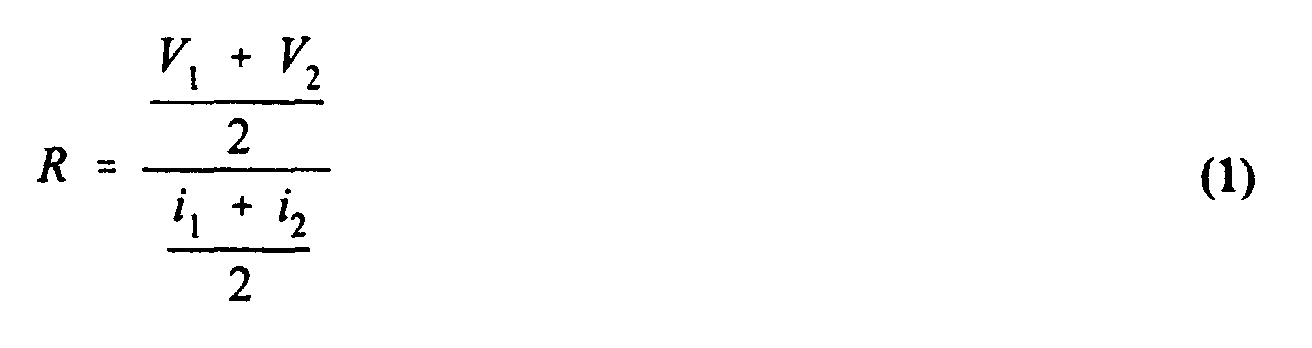
- the battery impedance may be determined by taking the quotient of the bus or battery voltage divided by its discharge current. The battery voltage and discharge current may be averaged.
- the step of controlling the electrical current output includes the step of controlling the electrical current production of a fuel cell, and in another version, it includes the step of controlling the engine speed of a rotary-engine-driven electrical generator.
- the step of processing the state-of-charge error signal includes the further step of multiplication of the integrated state-of-charge signal by the vehicle load current to produce a multiplied integrated state-of-charge error signal.
- the step of processing the multiplied integrated state-of-charge error signal includes the further steps of generation of a low-battery state signal, and addition of the low-battery state signal to the multiplied integrated state-of-charge error signal.
- the step of generation of a low-battery state signal includes the step of limiting the state-of-charge error signal to produce a limited state-of-charge error signal, and multiplying the limited state-of-charge error signal by a gain value.
- the step of estimating the state of charge of the battery includes the step of integrating the sum of the existing generator current and the load current.
- the step of controlling the electrical current output of the generator in response to the generator output current command may include the step of applying the generator output current command signal to control the rotational speed of an internal combustion engine coupled to a rotary electrical generator.
- An apparatus controls the charge state of a battery associated with a controllable auxiliary source of electrical power and a load.
- the apparatus includes the battery, and a state-of-charge estimator associated with the battery.
- a load current sensor is coupled to the load.
- the apparatus also includes a controllable electrical source, and a source current sensor coupled to the controllable electrical source, for generating a source current signal representing the current generated by the controllable electrical source.
- a power conveying means is coupled to the battery, the load, and to the controllable electrical source, for allowing power to flow to the load from the battery, the electrical source, or both the battery and the electrical source.
- a source of signal produces a signal representing a desired state of battery charge.
- a first error signal generator is coupled to the state-of-charge estimator and to the source of signal representing a desired state of battery charge, for taking the difference between the signals, for thereby generating a state-of-charge error signal.
- a first processing arrangement is coupled to the first error signal generator, for processing the state-of-charge error signal by at least integrating the state-of-charge error signal, to thereby produce a desired-source-signal representing the current to be produced by the controllable electrical source.
- a second error signal generator is coupled to the first processing arrangement and to the source current sensor, for taking the difference between the desired-source-signal and the source current signal, to thereby generate a source current error signal.
- a second processing arrangement is coupled to the second error signal generator, for processing the source current error signal by at least integration, to thereby produce a controllable electrical source control signal.
- a coupling arrangement is coupled to the second processing arrangement and to the controllable electrical source, for coupling the controllable electrical source control signal to the controllable electrical source for control thereof.
- the first processing arrangement includes a first switching arrangement.
- the first switching arrangement includes a control port, first and second switchable ports, and a common port to which one of the first and second switchable ports is connected under control of a logic signal applied to the control port (320c).
- a first path is coupled to the first error signal generator and to the first switchable port of the first switching arrangement.
- the first path includes a first integrator for integrating the state-of-charge error signal with a speed controlled by a first constant, to produce a first integrated state-of-charge signal.
- a source of a constant signal is coupled to the second switchable port of the first switching arrangement.
- the constant signal represents a fixed percentage of the load current.
- the fixed percentage may be 100% of the load current.
- a fast integrator is coupled to the first error signal generator, for at least integrating the state-of-charge error signal with a speed controlled by a second constant, which second constant is greater than the first constant of the first integrator, to generate a second integrated state-of-charge signal.
- a source of signal is provided, for producing a signal representing 100% of the load current.
- a summing circuit includes an inverting input port coupled to the fast integrator, and also includes a noninverting input port coupled to the source of signal representing 100% of the load current, for summing the signals applied to the summing circuit, to thereby produce signals representing that portion of the load current which is to be supplied by the battery.
- a signal comparison arrangement is coupled to the summing circuit and to the load current sensor, for comparing signals representative of the load current with the signals representing that portion of the load current which is to be supplied by the battery, and for, in response to the comparison, producing a first logic level, and for coupling the first logic level to the control input port of the first switching arrangement when the load current is the greater, and for producing a second logic level, and for coupling the second logic level to the control input port, when the signal representing that portion of the load current which is to be supplied by the battery is the greater, for thereby causing the switching arrangement to couple the common port to the first switchable port when the load current is the larger, and for causing the switching arrangement to couple the common port to the second switchable port when the signal representing that portion of the load current which is to be supplied by the battery is the greater.
- a summing arrangement includes a first input port coupled to the load current sensor and also includes a second input port, for summing together the signal representative of the load current with a signal applied to the second input port of the summing arrangement, to thereby produce the desired-source-current signals.
- a multiplying arrangement is coupled to the common port of the first switching arrangement and to the second input port of the summing arrangement, for multiplying by the load current signals that one of (a) the integrated state-of-charge signals and (b) the signals representing a fixed percentage of the load current which is coupled to the common port of the first switching arrangement.
- the first integrator is a state-limited integrator.
- the first processing arrangement further includes a limiter coupled to the summing arrangement and to the noninverting input port of the second error signal generator, for limiting the desired-source-current signal applied to the second error signal generator.
- the first processing arrangement further includes a source of signal representing the maximum current which is to be drawn from the battery, and a multiplier coupled to the summing circuit and to the source of signal representing the maximum current, for multiplying the signal representing that portion of the load current which is to be supplied by the battery by the signal representing the maximum current.
- FIGURE 1 is a simplified block diagram of a
- FIGURE 1 is a simplified block diagram of a system in accordance with an aspect of the invention.
- the system may be a hybrid electric vehicle 10, which includes an electrical generator 12.
- electrical generator 12 may be a rotary internal combustion engine coupled to a rotary electrical generator.
- Current produced by generator 12 is applied over a path 14 to a Hall-effect generator current sensor 16, which samples the generator current to produce a signal representing the instantaneous generator current on a path 18.
- the generator current is applied from sensor 16 over a bus 20 to a traction battery illustrated by a battery symbol 22 connected in parallel with the series combination of a load current sensor 23 and a load 24, which in a particular embodiment of the invention is a traction motor for the hybrid electric vehicle 10.
- a battery state-of-charge estimator is provided, which is illustrated in FIGURE 1 as being within a dashed box 26 associated with battery 22.
- State-of-charge estimator 26 produces, on a signal path 28, a signal representing an estimate of the state of charge of the battery 22.
- the signal on signal path 28 is applied to a processing arrangement depicted as being within a dot-dash outline 29.
- An error signal generator 30 takes the difference between the state-of-charge estimate received over signal path 28 and a signal representing the desired state of charge, which is generated by a block 32, to produce a state-of-charge error signal on a signal path 34.
- the state-of-charge error signal is processed in a block 36 by at least integrating, to produce, on a signal path 38, a signal representing the desired current which generator 12 is to generate.
- a further error signal generator 40 receives the signal representing the desired generator current from signal path 38, and also receives the signal representing the generator current from signal path 18, and takes the difference therebetween, in order to produce a generator current error signal on a signal path 42. Further processing, including at least integration, is performed in a processing block 44, to produce a generator control signal.
- the generator control signal is applied over a signal path 46 to control the electrical current output of the electrical generator 12. In the context of an engine/generator, the generator control signal commands the engine speed.
- the electrical generator in the context of a hybrid electric vehicle, may be an engine/generator combination.
- the load 24 is a traction motor for propelling the vehicle
- the battery is a traction battery.
- the traction battery may or may not provide ancillary vehicle power, such as air conditioning, lighting, and the like, depending upon the presence or absence of an auxiliary battery for such purposes.
- electrical generator block 12 may be a fuel cell rather than an engine/generator.
- FIGURE 2 is a simplified block diagram of state-of-charge estimator 26 of FIGURE 1.
- elements corresponding to those of FIGURE 1 are designated by the same reference numerals.
- a Hall-effect current sensor 210 measures the battery current, and produces a signal representative of battery current on a signal path 212.
- the signal representative of battery current is applied to a gain block 214 for multiplication by an integrator constant, and the multiplied battery current signal is then integrated (1/S) in a state-limited integrator 216, to produce the state-of-charge signal on signal path 28.
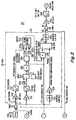
- FIGURE 3 is a simplified block diagram representing the processing arrangement of block 29 of FIGURE 1. Elements of FIGURE 1 which appear in FIGURE 3 are designated by like reference numerals.
- the estimated state-of-charge (SOC) signal is applied from a terminal 3 at the left of the FIGURE over signal path 28 to an inverting (-) input port of summing circuit 30.
- the desired state of charge signal is generated in block 32, and is applied to the inverting input port of summing circuit 30.
- the state-of-charge error signal produced by summing circuit 30 is applied to a current limiter 316, a multiplier 314, and to a multiplier 310.
- Multiplier 310 multiplies the state-of-charge error signal by a constant which controls the integration speed of a state-limited integrator 312.
- the multiplied, state-limited integrated SOC error signal produced at the output port of state-limited integrator 312 is applied to a first contact 320a of a single-pole, double-throw switch illustrated by a mechanical switch symbol 320, which is controlled by the logic level appearing at its control input port 320c.
- a switch for purposes of a control system is a solid-state switch, rather than a mechanical switch.
- the state-of-charge (SOC) error signal received by multiplier block 314 is multiplied by an integrator constant which is greater than the constant used in multiplier 310, for faster integration by a state-limited integrator 318, which limits the output values to lie between the values zero and one.
- the state-limited integrated output of state-limited integrator 318 is applied to an inverting input port of a summing circuit 322.
- Summing circuit 322 of FIGURE 3 sums the state-limited integrated signal with a value of unity or one produced by a generator 324.
- the value of unity produced by source or generator 324 may be viewed as representing the entirety of the load current, and the state-limited integrated signal from state-limited integrator 318 may be viewed as being related to the amount of current which the generator 12 (of FIGURE 1) is to supply.
- the sum produced by summing circuit 322 represents the 100% of the load current minus the percentage of the load current which the state-limited integral represents, which is the load current which the battery must supply.
- the value of the state-limited integral at the output port of integrator 318 were 0.6, then it would represent 60% of the reference value of unity produced by source 324, and the resulting output of summing circuit 322 would be 0.4, representing 40% of the load current to be supplied by the batteries.
- the value produced at the output of summing circuit 322 represents the percentage or proportion of the load current which the batteries are to supply.
- the output signal from summing circuit 322 is applied to a multiplier 324, in which the signal representing the percentage of the load current to be supplied by the battery is multiplied by a value produced by a battery power threshold signal generator 326, which represents the maximum power which the traction battery 22 (of FIGURE 1) can supply.
- a battery power threshold signal generator 326 which represents the maximum power which the traction battery 22 (of FIGURE 1) can supply.
- the percentage of the load current to be supplied by the battery as represented by the output signal from summing circuit 322 is multiplied by a value which represents the maximum power which the battery is permitted to supply, to produce a multiplied signal at the output of multiplier 324 which represents the current to be supplied by the battery.
- a comparator 328 is coupled to the multiplied output from multiplier 324 and to signal path 25 for receiving the load current signal, and produces a logic high or 1 if the multiplied output from multiplier 324 is less than the load current, and produces a logic zero otherwise. The resulting logic state is applied to control the state of switch 320. More particularly, if the multiplied output from multiplier 324 is less than the load current on path 25, comparator 328 produces a TRUE or logic high, which controls switch 320 to connect movable element 320M to the upper (T) contact, as illustrated in FIGURE 3.
- comparator 328 produces a FALSE or logic low, whereupon the movable element 320M connects to the F terminal rather than to the T terminal, thereupon coupling the unity or one signal produced by generator onto signal path 332.
- the state-of-charge error signal produced by summing circuit 30 of FIGURE 3 is limited in limiter 316, and multiplied by a constant in a multiplier 334.
- the output of multiplier 334 represents a compensator which increases the current command when the battery is at a low state of charge.
- a multiplier 336 in FIGURE 3 receives, over signal path 332, that one of the percent-of-load-current signals selected by switch 320, and also receives the load current signal, and multiplies them together, to produce a signal representing the amount of the load current which is to be provided by the generator.
- the signal from multiplier 336 is applied to a summing circuit 338, in which the signal representing the amount of the load current which is to be provided by the generator is summed with the compensator signal for increasing the generator current when the battery charge is low, thereby producing a signal representing the total generator current I tg .
- the total generator current I tg is applied to a limiter circuit 340, which represents the maximum-generator-current limitation.
- the limited total generator current signal is applied from limiter circuit 340 to the noninverting input port of summing circuit 40, and the generator current representative signal is applied over signal path 18 to the inverting input port.
- Summing circuit 40 produces an error signal on signal path 42 representing the difference between the desired generator current and the actual generator current.
- the generator current error signal produced by error signal generator 40 of FIGURE 3 is applied to serially connected blocks 44a and 44b, which together represent the gain of the state-limited integrator and the state-limited integrator itself, respectively.
- the integrated signal at the output of state-limited integrator 44b is applied over signal path 46 to terminal 4, for controlling the output current of generator 12 of FIGURE 1. In the context of an engine/generator combination, this signal controls the engine speed of the engine/generator combination.
- the state of charge can be estimated by measuring the battery impedance or resistance, which is accomplished by measuring the battery voltage or a battery-related voltage such as the bus voltage simultaneously with measurement of the battery discharge current, and determining the average quotient
- control system of the invention has been described in the context of a hybrid electric vehicle, it may be used in any system which includes batteries, a load, and an electrical power source for recharging the battery.
- load in the described example is a direct-current load
- an inverter may be connected electrically between the load and the bus when the load uses alternating current.
- the load is a polyphase FOC induction motor, but details of the motor drive are not necessary to an understanding of the invention.
- the method according to the invention may be performed by dedicated hardware, the preferred implementation of the signal processing is by software; in particular, the switch 320 is preferably a software switch.
- a method according to the invention for controlling the state of charge of a battery (22) of a hybrid electric vehicle (10) around a set state of charge which is less than full charge.
- Control is accomplished by controlling an electrical power generator (12), which may be an engine/generator combination, fuel cell, solar cell, or the like.
- the method includes the step of estimating the state of charge of the battery (22), to thereby generate (on signal path 28) a signal representative of the existing or present state of charge of the battery (22).
- a signal is generated (by a block 32) which is representative of the desired state of charge of the battery (22), which is a state less than full charge.
- the difference is taken (summing circuit 30) between the signal representative of the existing state of charge and the signal representative of the desired state of charge, to thereby generate (on signal path 34) a state-of-charge error signal.
- the state-of-charge error signal is processed (in block 36) by at least integration, to produce a desired generator (12) current signal (on a signal path 38) representative of the desired generator (12) current.
- the generator (12) current is sensed (by sensor 16) to produce an existing generator (12) current signal (on signal path 18).
- the difference is taken (in summing circuit 40) between the existing generator (12) current signal and the desired generator (12) current signal, to thereby produce a generator-current error signal (on signal path 42).
- the generator-current error signal is processed (in block 44), by at least integration, to produce a generator (12) output current command (on signal path 46).
- the generator (12) current output is controlled by the generator (12) output current command.
- the step of controlling the electrical current output includes the step of controlling the electrical current production of a fuel cell, and in another version, it includes the step of controlling the engine speed of a rotary-engine-driven electrical generator.
- the step of processing the state-of-charge error signal includes the further step of multiplication (214) of the integrated state-of-charge signal by the vehicle (10) load current to produce a multiplied integrated state-of-charge error signal (on signal path 28).
- the step of processing the multiplied integrated state-of-charge error signal includes the further steps of generation of a low-battery state signal, and addition of the low-battery state signal to the multiplied integrated state-of-charge error signal.
- the step of generation of a low-battery state signal includes the step of limiting the state-of-charge error signal to produce a limited state-of-charge error signal, and multiplying the limited state-of-charge error signal by a gain value.
- the step of estimating the state of charge of the battery (22) includes the step of integrating the sum of the existing generator (12) current and the load current.
- the step of controlling the electrical current output of the generator (12) in response to the generator (12) output current command may include the step of applying the generator (12) output current command signal to control the rotational speed of an internal combustion engine coupled to a rotary electrical generator.
- an apparatus (10) controls the charge state of a battery (22) associated with a controllable auxiliary source (12) of electrical power and a load (24).
- the apparatus (10) includes the battery (22), and a state-of-charge estimator (26) associated with the battery (22).
- a load current sensor (23) is coupled to the load (24).
- the apparatus (10) also includes a controllable electrical source (12), and a source current sensor (16) coupled to the controllable electrical source (12), for generating a source current signal representing the current generated by the controllable electrical source (12).
- a power conveyor (20) is coupled to the battery (22), the load (24), and to the controllable electrical source (12), for allowing power to flow among the load (24), the battery (22), and the electrical source (12).
- a source of signal (32) produces a signal representing a desired state (less than full charge) of battery (22) charge.
- a first error signal generator (30) is coupled to the state-of-charge estimator (26) and to the source of signal (32) representing a desired state of battery (22) charge, for taking the difference between the (state-of-charge estimate and the desired state-of-charge) signals, for thereby generating a state-of-charge error signal.
- a first processor (36) is coupled to the first error signal generator (30), for processing the state-of-charge error signal by at least integrating the state-of-charge error signal, to thereby produce a desired-source-current signal representing the current to be produced by the controllable electrical source (12).
- a second error signal generator (40) is coupled to the first processor (36) and to the source current sensor (16), for taking the difference between the desired-source-current signal and the source current signal, to thereby generate a source current error signal.
- a second processor (44) is coupled to the second error signal generator (40), for processing the source current error signal by at least integration, to thereby produce a controllable electrical source (12) control signal.
- a coupling arrangement (46) is coupled to the second processor (44) and to the controllable electrical source (12), for coupling the controllable electrical source (12) control signal to the controllable electrical source (12) for controlling the controllable electrical source (12).
- the first processing arrangement (36) includes a first switching arrangement (320).
- the first switching arrangement includes a control port (320c), first (320a) and second (320b) switchable ports, and a common port (320M) to which one of the first (320a) and second (320b) switchable ports is connected under control of a logic signal applied to the control port (320c.
- a first path (310, 312) is coupled to the first error signal generator (30) and to the first switchable port (320a) of the first switching arrangement (320).
- the first path includes a first integrator (312) for integrating the state-of-charge error signal with a speed controlled by a first constant, to produce a first integrated state-of-charge signal.
- a source (330) of a constant signal is coupled to the second switchable port (320b) of the first switching arrangement (320).
- the constant signal represents a fixed percentage of the load current. In one embodiment of the invention, the fixed percentage may be 100% of the load current.
- a fast integrator (314, 318) is coupled to the first error signal generator (30), for at least integrating the state-of-charge error signal with a speed controlled by a second constant, which second constant is greater than the first constant of the first integrator, to generate a second integrated state-of-charge signal.
- a source of signal (324) is provided, for producing a signal representing 100% of the load current.
- a summing circuit (322) includes an inverting input port coupled to the fast integrator (314, 318), and also includes a noninverting input port coupled to the source of signal (324) representing 100% of the load current, for summing the signals applied to the summing circuit, to thereby produce signals representing that portion of the load current which is to be supplied by the battery.
- a signal comparison arrangement (328) is coupled to the summing circuit (322) and to the load current sensor (23), for comparing signals representative of the load current with the signals representing that portion of the load current which is to be supplied by the battery, and for, in response to the comparison, producing a first logic level, and for coupling the first logic level to the control input port (320c) of the first switching arrangement (320) when the load current is the greater, and for producing a second logic level, and for coupling the second logic level to the control input port (320c), when the signal representing that portion of the load current which is to be supplied by the battery is the greater, for thereby causing the switching arrangement (320) to couple the common port (320M) to the first switchable port (320a) when the load current is the larger, and for causing the switching arrangement (320) to couple the common port (320M) to the second switchable port (320b) when the signal representing that portion of the load current which is to be supplied by the battery is the greater.
- a summing arrangement (338) includes a first input port coupled to the load current sensor (23) and also includes a second input port, for summing together the signal representative of the load current with a signal applied to the second input port of the summing arrangement (338), to thereby produce the desired-source-current signals.
- a multiplying arrangement (336) is coupled to the common port (320M) of the first switching arrangement (320) and to the second input port of the summing arrangement (338), for multiplying by the load current signals that one of (a) the integrated state-of-charge signals and (b) the signals representing a fixed percentage of the load current which is coupled to the common port (320M) of the first switching arrangement (320).
- the first integrator is a state-limited integrator.
- the first processing arrangement further includes a limiter (340) coupled to the summing arrangement (338) and to the noninverting input port of the second error signal generator (40), for limiting the desired-source-current signal (I tg ) applied to the second error signal generator.
- the first processing arrangement further includes a source of signal (326) representing the maximum current which is to be drawn from the battery (22), and a multiplier (324) coupled to the summing circuit (322) and to the source of signal representing the maximum current, for multiplying the signal representing that portion of the load current which is to be supplied by the battery (22) by the signal representing the maximum current.
Landscapes
- Engineering & Computer Science (AREA)
- Combustion & Propulsion (AREA)
- Chemical & Material Sciences (AREA)
- Transportation (AREA)
- Mechanical Engineering (AREA)
- Life Sciences & Earth Sciences (AREA)
- Sustainable Development (AREA)
- Sustainable Energy (AREA)
- Power Engineering (AREA)
- Automation & Control Theory (AREA)
- Electric Propulsion And Braking For Vehicles (AREA)
- Secondary Cells (AREA)
- Charge And Discharge Circuits For Batteries Or The Like (AREA)
- Hybrid Electric Vehicles (AREA)
- Fuel Cell (AREA)
- Control Of Vehicle Engines Or Engines For Specific Uses (AREA)
- Control Of Eletrric Generators (AREA)
Abstract
Description
Claims (17)
- A method for controlling the state of charge of a battery (22) of a hybrid electric vehicle (10) around a set state of charge which is less than full charge, by controlling an electrical power generator (12), said method comprising the steps of:estimating the state of charge of said battery to generate signals representative of the existing state of charge of said battery (22);generating signals representative of the desired state of charge of said battery (22);taking the difference between said signals representative of the existing (present) state of charge and said signals representative of the desired state of charge to generate state-of-charge error signals;processing said state-of-charge error signals by at least integrating, to produce desired generator current signals;sensing the generator current to produce existing generator current signals;taking the difference between said existing generator current signals and said desired generator current signals to produce generator-current error signals;processing said generator-current error signals by at least integration to produce a generator output current command; andcontrolling the electrical current output of said generator in response to said generator output current command.
- A method according to claim 1, wherein said step of controlling the electrical current output includes the step of controlling the electrical current production of a fuel cell.
- A method according to claim 1, wherein said step of controlling the electrical current output includes the step of controlling the engine speed of an engine-driven electrical generator.
- A method according to claim 1, 2 or 3, wherein said step of processing said state-of-charge error signals includes the further step of multiplication of said integrated state-of-charge by the vehicle load current to produce multiplied integrated state-of-charge error signals.
- A method according to claim 4, wherein said step of processing said multiplied integrated state-of-charge error signals includes the further steps of generation of low-battery state signals, and addition of said low-battery state signals to said multiplied integrated state-of-charge error signals.
- A method according to claim 5, wherein said step of generation of low-battery state signals includes the step of limiting said state-of-charge error signals to produce limited state-of-charge error signals, and multiplying said limited state-of-charge error signals by a gain value.
- A method according to one of the claims 1 to 6, wherein said step of estimating the state of charge of said battery (22) includes the steps of:integrating the sum of said existing generator current and said load current.
- A method according to one of the claims 1 to 7, wherein said step of estimating the state of charge of said battery (22) includes the step of measuring the discharge current of said battery (22), and the step of measuring the battery voltage during said discharge, add the further step of calculating the battery impedance as the quotient of battery voltage divided by battery current.
- A method according to claim 8, wherein said steps of measuring battery discharge current and battery voltage are carried out in a recurrent manner to thereby produce a time-quantized stream of current and voltage data, and said step of calculating includes the step of averaging said time-quantized stream of voltage and current data over a selected number of time-quantized occurrences.
- A method according to one of the claims 1 to 9, wherein said step of controlling the electrical current output of said generator (12) in response to said generator output current command includes the step of applying said generator output current command signals to control the rotational speed of an internal combustion engine coupled to a rotary electrical generator.
- A method for controlling the impedance of a battery (22) of a hybrid electric vehicle (10) around a set impedance by controlling an electrical power generator (12), said method comprising the steps of:estimating the impedance of said battery (22) to generate signals representative of the existing impedance of said battery (22);generating signals representative of the desired impedance of said battery (22);taking the difference between said signals representative of the existing impedance and said signals representative of the desired impedance to generate impedance error signals;processing said impedance error signals by at least integrating, to produce desired generator current signals;sensing the generator current to produce existing generator current signals;taking the difference between said existing generator current signals and said desired generator current signals to produce generator-current error signals;processing said generator-current error signals by at least integration to produce a generator speed command; andcontrolling the electrical current output of said generator (12) in response to said generator speed command.
- A method according to claim 11, wherein said step of estimating the impedance of said battery (22) comprises the steps of:measuring the battery discharge current to produce first and second current samples at first and second times;measuring a voltage related to the battery voltage at said first and second times, to thereby produce first and second battery voltage samples:averaging said first and second current samples to produce averaged battery discharge current;averaging said first and second battery voltage samples to produce averaged battery voltage; anddetermining the battery impedance as the quotient of said averaged battery voltage divided by said averaged battery discharge current.
- An apparatus for controlling the charge state of a battery (22) associated with a controllable auxiliary source of electrical power and a load, said apparatus comprising:a state-of-charge estimator associated with said battery (26);a load (24);a load current sensor (23) coupled to said load (24);a controllable electrical source (12);a source current sensor (16) coupled to said controllable electrical source (12), for generating source current signals representing the current generated by said controllable electrical source (12);power conveying means coupled to said battery (22), said load (24), and to said controllable electrical source (12), for allowing power to flow among said load (24), said battery (22), and said electrical source (12);a source of signals (32) representing a desired state of battery charge;a first error signal generator (30) coupled to said state-of-charge estimator and to said source of signal (32) representing a desired state of battery charge, for taking the difference therebetween, for generating state-of-charge error signals;first processing means (36) coupled to said first error signal generator (30), for processing said state-of-charge error signals by at least integrating said state-of-charge error signals, to thereby produce desired-source-current signals representing the current to be produced by said controllable electrical source (12);second error signal generating means (40) coupled to said first processing means (36) and to said source current sensor (16), for taking the difference between said desired-source-current signals and said source current signals, to thereby generate source current error signals;second processing means (44) coupled to said second error signal generating means (40), for processing said source current error signals by at least integration, to thereby produce controllable electrical source control signals; andcoupling means coupled to said second processing means (44) and to said controllable electrical source (12), for coupling said controllable electrical source control signals to said controllable electrical source for controlling said controllable electrical source (12).
- An apparatus according to claim 13, wherein said first processing means (36) comprises:first switching means (320) including a control port (320c), first (320a) and second (320b) switchable ports, and a common port to which one of said first and second switchable ports is connected under control of logic signals applied to said control port (320c);a first path coupled to said first error signal generator (30) and to said first switchable port (320a) of said first switching means (320), said first path including a first integrator (312) for integrating said state-of-charge error signals with a speed controlled by a first constant, to produce first integrated state-of-charge signals;a source of a constant signal (330) coupled to said second switchable port (320b) of said first switching means (320), said constant signal representing a fixed percentage of the load current, which may be 100% of the load current;a fast integrator (318) coupled to said first error signal generator (30) for at least integrating said state-of-charge error signals with a speed controlled by a second constant, greater than said first constant of said first integrator (312), to generate second integrated state-of-charge signals;a source of signal (324) representing 100% of the load current;a summing circuit (322) including an inverting input port coupled to said fast integrator (318) and a noninverting input port coupled to said source of signals (324) representing 100% of the load current, for summing the signals applied thereto, to thereby produce signals representing that portion of the load current which is to be supplied by said battery (22);signal comparison means coupled to said summing circuit (322) and to said load current sensor (23), for comparing signals representative of the load current with said signals representing that portion of the load current which is to be supplied by said battery (22), and for producing a first logic level, and for coupling said first logic level to said control input port (320c) of said first switching means (320) when said load current is the greater, and for producing a second logic level, and for coupling said second logic level to said control input port (320c) when said signals representing that portion of the load current which is to be supplied by said battery is the greater, for thereby causing said switching means (320) to couple said common port to said first switchable port when said load current is the larger, and for causing said switching means (320) to couple said common port to said second switchable port (320b) when said signals representing that portion of the load current which is to be supplied by said battery is the greater;summing means (338) including a first input port coupled to said load current sensor (23) and also including a second input port, for summing together said signals representative of the load current with signals applied to said second input port of said summing means (338), to thereby produce said desired source-current-signals;multiplying means (336) coupled to said common port of said first switching means (320) and to said second input port of said summing means (336), for multiplying by the load current signals that one of said integrated state-of-charge signals and said signals representing a fixed precentage of the load current which is coupled to said common port of said first switching means (320).
- An apparatus according to claim 14, wherein said first integrator (312) is a state-limited integrator.
- An apparatus according to claim 14 or 15, further comprising a limiter (340) coupled to said summing means (338) and to said noninverting input port of said second error signal generator (40), for limiting said desired-source-current signals applied to said second error signal generator (40).
- An apparatus according to claim 14, 15 or 16, further comprising:a source of signals (326) representing the maximum current which is to be drawn from said battery (22);a multiplier (324) coupled to said summing circuit and to said source of signals (326) representing the maximum current, for multiplying said signals representing that portion of the load current which is to be supplied by said battery by said signals representing the maximum current.
Applications Claiming Priority (4)
| Application Number | Priority Date | Filing Date | Title |
|---|---|---|---|
| US8339998P | 1998-04-29 | 1998-04-29 | |
| US83399P | 1998-04-29 | ||
| US177011 | 1998-10-22 | ||
| US09/177,011 US6091228A (en) | 1998-04-29 | 1998-10-22 | Control system for, in the presence of a varying system load, establishing generator current to maintain a particular battery charge state |
Publications (3)
| Publication Number | Publication Date |
|---|---|
| EP0953472A2 true EP0953472A2 (en) | 1999-11-03 |
| EP0953472A3 EP0953472A3 (en) | 2001-02-14 |
| EP0953472B1 EP0953472B1 (en) | 2007-09-12 |
Family
ID=26769253
Family Applications (1)
| Application Number | Title | Priority Date | Filing Date |
|---|---|---|---|
| EP99108275A Expired - Lifetime EP0953472B1 (en) | 1998-04-29 | 1999-04-27 | Control system to maintain battery charge state in a hybrid vehicule |
Country Status (10)
| Country | Link |
|---|---|
| US (1) | US6091228A (en) |
| EP (1) | EP0953472B1 (en) |
| JP (2) | JP4174132B2 (en) |
| KR (1) | KR100575553B1 (en) |
| CN (1) | CN1135674C (en) |
| AR (1) | AR016231A1 (en) |
| BR (1) | BR9901400A (en) |
| CA (1) | CA2269560C (en) |
| DE (1) | DE69937084T2 (en) |
| DK (1) | DK0953472T3 (en) |
Cited By (5)
| Publication number | Priority date | Publication date | Assignee | Title |
|---|---|---|---|---|
| WO2002080332A1 (en) * | 2001-03-30 | 2002-10-10 | Designline Limited | Battery management unit, system and method |
| WO2001070533A3 (en) * | 2000-03-21 | 2003-04-03 | Nissan Motor | Control device for hybrid vehicle |
| US7847513B2 (en) | 2006-06-09 | 2010-12-07 | Gm Global Technology Operations, Inc. | System for controlling the power output of a fuel cell stack and battery |
| CN103072462A (en) * | 2004-11-12 | 2013-05-01 | 杨泰和 | Separated series-parallel connection hybrid double-power driving system |
| EP3771059A1 (en) | 2019-07-25 | 2021-01-27 | Airbus Helicopters | Method for supplying electricity to an electrical network and electrical architecture |
Families Citing this family (31)
| Publication number | Priority date | Publication date | Assignee | Title |
|---|---|---|---|---|
| JP5079186B2 (en) * | 1998-07-20 | 2012-11-21 | ハネウェル・インターナショナル・インコーポレーテッド | System and method for monitoring a vehicle battery |
| US6672415B1 (en) * | 1999-05-26 | 2004-01-06 | Toyota Jidosha Kabushiki Kaisha | Moving object with fuel cells incorporated therein and method of controlling the same |
| US6362535B1 (en) | 1999-08-11 | 2002-03-26 | Bae Systems | Method and apparatus for after-treatment of hev exhaust |
| EP1132251A4 (en) * | 1999-08-27 | 2011-08-31 | Yamaha Motor Co Ltd | HYBRID TRAINING SYSTEM |
| DE10024259C1 (en) * | 2000-05-17 | 2002-01-03 | Xcellsis Gmbh | Automatic correction of demand current values for operating drive unit(s) involves adding dynamically corrected difference demand if difference exists between consumed current, sum value |
| US6362602B1 (en) | 2001-05-03 | 2002-03-26 | Ford Global Technologies, Inc. | Strategy to control battery state of charge based on vehicle velocity |
| EP1420497B1 (en) * | 2002-11-15 | 2018-06-20 | Ford Global Technologies, LLC | Method for regulating battery power in a vehicle |
| DE10346213A1 (en) * | 2003-10-06 | 2005-04-21 | Bosch Gmbh Robert | Regulating load condition of energy storage device for vehicle with hybrid drive involves regulating state of charge of energy storage device depending on vehicle's speed of travel |
| JP4003798B2 (en) * | 2003-11-20 | 2007-11-07 | 松下電器産業株式会社 | Vehicle power supply |
| JP2005354825A (en) * | 2004-06-11 | 2005-12-22 | Nissan Motor Co Ltd | SOC calculation device for hybrid vehicle |
| US7960855B2 (en) * | 2004-12-15 | 2011-06-14 | General Electric Company | System and method for providing power control of an energy storage system |
| US7525286B2 (en) * | 2004-12-31 | 2009-04-28 | Jason Auto Technology Co., Ltd. | Method and device for vehicle battery protection with battery power source noise pattern analysis |
| WO2007032382A1 (en) * | 2005-09-16 | 2007-03-22 | The Furukawa Electric Co., Ltd | Secondary cell degradation judgment method, secondary cell degradation judgment device, and power supply system |
| DE102006042867B4 (en) * | 2006-09-13 | 2015-02-19 | Ford Global Technologies, Llc | A method of operating an internal combustion engine with an exhaust aftertreatment device |
| JP4811301B2 (en) * | 2007-03-06 | 2011-11-09 | トヨタ自動車株式会社 | Secondary battery input / output control device and vehicle |
| FR2916049B1 (en) * | 2007-05-11 | 2009-07-03 | Commissariat Energie Atomique | METHOD FOR DIAGNOSING DEFECTIVE ELEMENTS IN AN AUTONOMOUS SYSTEM POWERED BY AN INTERMITTENT POWER SOURCE |
| WO2009059164A2 (en) * | 2007-10-31 | 2009-05-07 | Intrago Corporation | User-distributed shared vehicle system |
| JP5217430B2 (en) | 2007-12-28 | 2013-06-19 | トヨタ自動車株式会社 | Alternator control device and alternator control method |
| US7779616B2 (en) * | 2008-06-03 | 2010-08-24 | Deere & Company | Vehicle with electric hybrid powering of external loads and engine-off capability |
| JP2011053095A (en) * | 2009-09-02 | 2011-03-17 | Furukawa Electric Co Ltd:The | Current monitoring device |
| KR101367875B1 (en) * | 2011-03-21 | 2014-02-26 | 주식회사 엘지화학 | Apparatus for controlling connection of battery pack |
| US8768549B2 (en) | 2011-11-04 | 2014-07-01 | Tennant Company | Battery maintenance system |
| CN103185863B (en) * | 2011-12-31 | 2017-06-20 | 山特电子(深圳)有限公司 | The evaluation method and system of battery backup time in the case of varying load |
| US9718456B2 (en) * | 2015-03-26 | 2017-08-01 | Ford Global Technologies, Llc | Torque assist based on battery state of charge allocation |
| JP6686704B2 (en) * | 2016-05-31 | 2020-04-22 | 株式会社デンソー | Control device |
| JP6583294B2 (en) * | 2017-01-17 | 2019-10-02 | トヨタ自動車株式会社 | Electric vehicle |
| CN109383298B (en) * | 2017-08-04 | 2021-09-24 | 中车大同电力机车有限公司 | Automatic switching method for operation terminal of urban tramcar |
| JP6617189B1 (en) | 2018-10-31 | 2019-12-11 | 日本たばこ産業株式会社 | Power supply unit for aerosol inhaler, aerosol inhaler, power control method for aerosol inhaler, and power control program for aerosol inhaler |
| CN112311075B (en) * | 2019-07-29 | 2022-06-24 | 广州汽车集团股份有限公司 | Solar-energy-based automobile energy storage control method and device and automobile |
| CN112158102B (en) * | 2020-09-04 | 2024-03-19 | 开沃新能源汽车集团股份有限公司 | Peak current control method of vehicle-mounted lithium battery system |
| CN113131580A (en) * | 2021-04-21 | 2021-07-16 | 广东电网有限责任公司广州供电局 | Direct current power supply method and device and terminal equipment |
Family Cites Families (9)
| Publication number | Priority date | Publication date | Assignee | Title |
|---|---|---|---|---|
| GB1432318A (en) * | 1973-07-04 | 1976-04-14 | Vdo Schindling | Apparatus for determining the state of charge of accumulator |
| DE3031890C2 (en) * | 1980-06-28 | 1987-02-05 | Lucas Industries Ltd., Birmingham, West Midlands | Method for charging an accumulator battery |
| DE3218148C2 (en) * | 1982-05-14 | 1984-05-03 | Deta-Akkumulatorenwerk Gmbh, 3422 Bad Lauterberg | Method and device for displaying the discharge status and for controlling the charging of a drive accumulator |
| US4937528A (en) * | 1988-10-14 | 1990-06-26 | Allied-Signal Inc. | Method for monitoring automotive battery status |
| US4876513A (en) * | 1988-12-05 | 1989-10-24 | Globe-Union Inc. | Dynamic state-of-charge indicator for a battery and method thereof |
| US5488300A (en) * | 1994-10-21 | 1996-01-30 | Jamieson; Robert S. | Method and apparatus for monitoring the state of charge of a battery |
| JPH08205312A (en) * | 1995-01-19 | 1996-08-09 | Nippondenso Co Ltd | Method and equipment for controlling series hybrid vehicle |
| US5659240A (en) * | 1995-02-16 | 1997-08-19 | General Electric Company | Intelligent battery charger for electric drive system batteries |
| JP4049833B2 (en) * | 1996-07-26 | 2008-02-20 | トヨタ自動車株式会社 | Power supply device and electric vehicle |
-
1998
- 1998-10-22 US US09/177,011 patent/US6091228A/en not_active Expired - Lifetime
-
1999
- 1999-04-20 CA CA002269560A patent/CA2269560C/en not_active Expired - Lifetime
- 1999-04-23 BR BR9901400-9A patent/BR9901400A/en not_active Application Discontinuation
- 1999-04-27 AR ARP990101955A patent/AR016231A1/en active IP Right Grant
- 1999-04-27 EP EP99108275A patent/EP0953472B1/en not_active Expired - Lifetime
- 1999-04-27 KR KR1019990015015A patent/KR100575553B1/en not_active Expired - Fee Related
- 1999-04-27 DK DK99108275T patent/DK0953472T3/en active
- 1999-04-27 DE DE69937084T patent/DE69937084T2/en not_active Expired - Lifetime
- 1999-04-29 CN CNB991079582A patent/CN1135674C/en not_active Expired - Lifetime
- 1999-04-30 JP JP12419899A patent/JP4174132B2/en not_active Expired - Fee Related
-
2008
- 2008-07-01 JP JP2008172831A patent/JP4295809B2/en not_active Expired - Fee Related
Cited By (12)
| Publication number | Priority date | Publication date | Assignee | Title |
|---|---|---|---|---|
| WO2001070533A3 (en) * | 2000-03-21 | 2003-04-03 | Nissan Motor | Control device for hybrid vehicle |
| US6659213B2 (en) | 2000-03-21 | 2003-12-09 | Nissan Motor Co., Ltd. | Control device for hybrid vehicle |
| WO2002080332A1 (en) * | 2001-03-30 | 2002-10-10 | Designline Limited | Battery management unit, system and method |
| CN100386941C (en) * | 2001-03-30 | 2008-05-07 | 运输设计有限公司 | Battery management unit, system and method |
| US7400113B2 (en) | 2001-03-30 | 2008-07-15 | Designline International Holdings, Llc | Battery management unit, system and method |
| CN103072462A (en) * | 2004-11-12 | 2013-05-01 | 杨泰和 | Separated series-parallel connection hybrid double-power driving system |
| CN103072462B (en) * | 2004-11-12 | 2016-12-28 | 杨泰和 | Separate series-parallel hybrid dual power drive system |
| US7847513B2 (en) | 2006-06-09 | 2010-12-07 | Gm Global Technology Operations, Inc. | System for controlling the power output of a fuel cell stack and battery |
| DE102007026329B4 (en) * | 2006-06-09 | 2012-12-06 | GM Global Technology Operations LLC (n. d. Ges. d. Staates Delaware) | Fuel cell system and its use and method for distributing power between a fuel cell stack and a battery in a fuel cell system |
| EP3771059A1 (en) | 2019-07-25 | 2021-01-27 | Airbus Helicopters | Method for supplying electricity to an electrical network and electrical architecture |
| FR3099134A1 (en) * | 2019-07-25 | 2021-01-29 | Airbus Helicopters | Power supply method for an electrical network and electrical architecture |
| US11554875B2 (en) | 2019-07-25 | 2023-01-17 | Airbus Helicopters | Method of electrically powering an electricity network, and an electrical architecture |
Also Published As
| Publication number | Publication date |
|---|---|
| CA2269560A1 (en) | 1999-10-29 |
| EP0953472A3 (en) | 2001-02-14 |
| DE69937084T2 (en) | 2008-06-12 |
| KR19990083526A (en) | 1999-11-25 |
| CA2269560C (en) | 2007-01-09 |
| JP2009023645A (en) | 2009-02-05 |
| JP2000059916A (en) | 2000-02-25 |
| JP4295809B2 (en) | 2009-07-15 |
| DK0953472T3 (en) | 2008-01-21 |
| EP0953472B1 (en) | 2007-09-12 |
| BR9901400A (en) | 2000-01-18 |
| US6091228A (en) | 2000-07-18 |
| DE69937084D1 (en) | 2007-10-25 |
| CN1238588A (en) | 1999-12-15 |
| AR016231A1 (en) | 2001-06-20 |
| JP4174132B2 (en) | 2008-10-29 |
| KR100575553B1 (en) | 2006-05-03 |
| CN1135674C (en) | 2004-01-21 |
Similar Documents
| Publication | Publication Date | Title |
|---|---|---|
| US6091228A (en) | Control system for, in the presence of a varying system load, establishing generator current to maintain a particular battery charge state | |
| CN105322613B (en) | Fast charging algorithm for lithium ion batteries | |
| CN107009905B (en) | Vehicle control based on lithium plating detection in electrified vehicle battery | |
| US7456612B2 (en) | Method for estimating polarization voltage of secondary cell, method and device for estimating remaining capacity of secondary cell, battery pack system, and vehicle | |
| CN108819731B (en) | Charge rate estimation method and vehicle-mounted battery system | |
| US10809305B2 (en) | System and method for detecting and responding to a battery over-discharge condition within a vehicle | |
| US7339351B2 (en) | Method and apparatus for estimating remaining capacity of secondary battery | |
| US8000915B2 (en) | Method for estimating state of charge of a rechargeable battery | |
| CN106828134B (en) | Adaptive identification of connection resistance in traction battery | |
| US11685288B2 (en) | Intelligent motor vehicles and control logic for managing charging of traction battery packs | |
| US20180162232A1 (en) | A method and system for optimizing the lifetime of an energy storage system | |
| CN113228345A (en) | Battery state estimation device, battery state estimation method, and battery system | |
| CN108702004B (en) | Method and system for controlling current fed to a battery pack | |
| JP2001330654A (en) | Battery remaining capacity estimation device | |
| CN111289907B (en) | Degradation estimation device for secondary battery and degradation estimation method for secondary battery | |
| JP2001086604A (en) | Battery pack and remaining capacity detection device | |
| US11218012B2 (en) | Secondary battery system and method for controlling charging of secondary battery | |
| CN104104131A (en) | Battery charge/discharge control apparatus | |
| JP2001211507A (en) | Hybrid vehicle control device | |
| JP2000217206A (en) | Electric vehicle charging control device | |
| US12576747B2 (en) | Electrified vehicle control using traction battery array-based multi-cell state estimation | |
| MXPA99004011A (en) | Control system for, in the presence of a variant system load, to establish generator current to maintain a particular state of bate load | |
| JPH10271695A (en) | Battery remaining capacity detection device and power generation control device for hybrid electric vehicle | |
| JP3628912B2 (en) | Battery charge state detection device | |
| CN110733380A (en) | Traction battery with cell area monitoring |
Legal Events
| Date | Code | Title | Description |
|---|---|---|---|
| PUAI | Public reference made under article 153(3) epc to a published international application that has entered the european phase |
Free format text: ORIGINAL CODE: 0009012 |
|
| AK | Designated contracting states |
Kind code of ref document: A2 Designated state(s): DE DK FR GB IT NL SE |
|
| AX | Request for extension of the european patent |
Free format text: AL;LT;LV;MK;RO;SI |
|
| PUAL | Search report despatched |
Free format text: ORIGINAL CODE: 0009013 |
|
| AK | Designated contracting states |
Kind code of ref document: A3 Designated state(s): AT BE CH CY DE DK ES FI FR GB GR IE IT LI LU MC NL PT SE |
|
| AX | Request for extension of the european patent |
Free format text: AL;LT;LV;MK;RO;SI |
|
| RIC1 | Information provided on ipc code assigned before grant |
Free format text: 7B 60L 11/18 A, 7H 02J 7/14 B |
|
| 17P | Request for examination filed |
Effective date: 20010717 |
|
| AKX | Designation fees paid |
Free format text: DE DK FR GB IT NL SE |
|
| RAP1 | Party data changed (applicant data changed or rights of an application transferred) |
Owner name: BAE SYSTEMS CONTROLS, INC. |
|
| GRAP | Despatch of communication of intention to grant a patent |
Free format text: ORIGINAL CODE: EPIDOSNIGR1 |
|
| GRAS | Grant fee paid |
Free format text: ORIGINAL CODE: EPIDOSNIGR3 |
|
| GRAA | (expected) grant |
Free format text: ORIGINAL CODE: 0009210 |
|
| AK | Designated contracting states |
Kind code of ref document: B1 Designated state(s): DE DK FR GB IT NL SE |
|
| REG | Reference to a national code |
Ref country code: GB Ref legal event code: FG4D |
|
| REF | Corresponds to: |
Ref document number: 69937084 Country of ref document: DE Date of ref document: 20071025 Kind code of ref document: P |
|
| REG | Reference to a national code |
Ref country code: SE Ref legal event code: TRGR |
|
| REG | Reference to a national code |
Ref country code: DK Ref legal event code: T3 |
|
| ET | Fr: translation filed | ||
| PLBE | No opposition filed within time limit |
Free format text: ORIGINAL CODE: 0009261 |
|
| STAA | Information on the status of an ep patent application or granted ep patent |
Free format text: STATUS: NO OPPOSITION FILED WITHIN TIME LIMIT |
|
| 26N | No opposition filed |
Effective date: 20080613 |
|
| PGFP | Annual fee paid to national office [announced via postgrant information from national office to epo] |
Ref country code: SE Payment date: 20150429 Year of fee payment: 17 |
|
| REG | Reference to a national code |
Ref country code: FR Ref legal event code: PLFP Year of fee payment: 18 |
|
| PGFP | Annual fee paid to national office [announced via postgrant information from national office to epo] |
Ref country code: DK Payment date: 20160425 Year of fee payment: 18 |
|
| REG | Reference to a national code |
Ref country code: SE Ref legal event code: EUG |
|
| PG25 | Lapsed in a contracting state [announced via postgrant information from national office to epo] |
Ref country code: SE Free format text: LAPSE BECAUSE OF NON-PAYMENT OF DUE FEES Effective date: 20160428 |
|
| REG | Reference to a national code |
Ref country code: FR Ref legal event code: PLFP Year of fee payment: 19 |
|
| REG | Reference to a national code |
Ref country code: DK Ref legal event code: EBP Effective date: 20170430 |
|
| REG | Reference to a national code |
Ref country code: FR Ref legal event code: PLFP Year of fee payment: 20 |
|
| PG25 | Lapsed in a contracting state [announced via postgrant information from national office to epo] |
Ref country code: DK Free format text: LAPSE BECAUSE OF NON-PAYMENT OF DUE FEES Effective date: 20170430 |
|
| PGFP | Annual fee paid to national office [announced via postgrant information from national office to epo] |
Ref country code: NL Payment date: 20180426 Year of fee payment: 20 |
|
| PGFP | Annual fee paid to national office [announced via postgrant information from national office to epo] |
Ref country code: DE Payment date: 20180427 Year of fee payment: 20 |
|
| PGFP | Annual fee paid to national office [announced via postgrant information from national office to epo] |
Ref country code: FR Payment date: 20180425 Year of fee payment: 20 Ref country code: IT Payment date: 20180423 Year of fee payment: 20 |
|
| PGFP | Annual fee paid to national office [announced via postgrant information from national office to epo] |
Ref country code: GB Payment date: 20180427 Year of fee payment: 20 |
|
| REG | Reference to a national code |
Ref country code: DE Ref legal event code: R079 Ref document number: 69937084 Country of ref document: DE Free format text: PREVIOUS MAIN CLASS: B60L0011180000 Ipc: B60L0050500000 |
|
| REG | Reference to a national code |
Ref country code: DE Ref legal event code: R071 Ref document number: 69937084 Country of ref document: DE |
|
| REG | Reference to a national code |
Ref country code: NL Ref legal event code: MK Effective date: 20190426 |
|
| REG | Reference to a national code |
Ref country code: GB Ref legal event code: PE20 Expiry date: 20190426 |
|
| PG25 | Lapsed in a contracting state [announced via postgrant information from national office to epo] |
Ref country code: GB Free format text: LAPSE BECAUSE OF EXPIRATION OF PROTECTION Effective date: 20190426 |