EP1420497B1 - Method for regulating battery power in a vehicle - Google Patents
Method for regulating battery power in a vehicle Download PDFInfo
- Publication number
- EP1420497B1 EP1420497B1 EP02102591.1A EP02102591A EP1420497B1 EP 1420497 B1 EP1420497 B1 EP 1420497B1 EP 02102591 A EP02102591 A EP 02102591A EP 1420497 B1 EP1420497 B1 EP 1420497B1
- Authority
- EP
- European Patent Office
- Prior art keywords
- battery
- power
- motor vehicle
- electrical
- generated
- Prior art date
- Legal status (The legal status is an assumption and is not a legal conclusion. Google has not performed a legal analysis and makes no representation as to the accuracy of the status listed.)
- Expired - Lifetime
Links
Images
Classifications
-
- H—ELECTRICITY
- H02—GENERATION; CONVERSION OR DISTRIBUTION OF ELECTRIC POWER
- H02J—CIRCUIT ARRANGEMENTS OR SYSTEMS FOR SUPPLYING OR DISTRIBUTING ELECTRIC POWER; SYSTEMS FOR STORING ELECTRIC ENERGY
- H02J7/00—Circuit arrangements for charging or depolarising batteries or for supplying loads from batteries
- H02J7/14—Circuit arrangements for charging or depolarising batteries or for supplying loads from batteries for charging batteries from dynamo-electric generators driven at varying speed, e.g. on vehicle
- H02J7/1446—Circuit arrangements for charging or depolarising batteries or for supplying loads from batteries for charging batteries from dynamo-electric generators driven at varying speed, e.g. on vehicle in response to parameters of a vehicle
-
- H—ELECTRICITY
- H02—GENERATION; CONVERSION OR DISTRIBUTION OF ELECTRIC POWER
- H02J—CIRCUIT ARRANGEMENTS OR SYSTEMS FOR SUPPLYING OR DISTRIBUTING ELECTRIC POWER; SYSTEMS FOR STORING ELECTRIC ENERGY
- H02J7/00—Circuit arrangements for charging or depolarising batteries or for supplying loads from batteries
- H02J7/14—Circuit arrangements for charging or depolarising batteries or for supplying loads from batteries for charging batteries from dynamo-electric generators driven at varying speed, e.g. on vehicle
- H02J7/1438—Circuit arrangements for charging or depolarising batteries or for supplying loads from batteries for charging batteries from dynamo-electric generators driven at varying speed, e.g. on vehicle in combination with power supplies for loads other than batteries
-
- Y—GENERAL TAGGING OF NEW TECHNOLOGICAL DEVELOPMENTS; GENERAL TAGGING OF CROSS-SECTIONAL TECHNOLOGIES SPANNING OVER SEVERAL SECTIONS OF THE IPC; TECHNICAL SUBJECTS COVERED BY FORMER USPC CROSS-REFERENCE ART COLLECTIONS [XRACs] AND DIGESTS
- Y02—TECHNOLOGIES OR APPLICATIONS FOR MITIGATION OR ADAPTATION AGAINST CLIMATE CHANGE
- Y02T—CLIMATE CHANGE MITIGATION TECHNOLOGIES RELATED TO TRANSPORTATION
- Y02T10/00—Road transport of goods or passengers
- Y02T10/80—Technologies aiming to reduce greenhouse gasses emissions common to all road transportation technologies
- Y02T10/92—Energy efficient charging or discharging systems for batteries, ultracapacitors, supercapacitors or double-layer capacitors specially adapted for vehicles
Definitions
- the invention relates to a method for regulating the electric battery power, which is supplied to or taken from the battery of the motor vehicle coupled to the electrical system of a motor vehicle, wherein the total electrical power consumed by the motor vehicle is generated by a generator coupled to the internal combustion engine of the motor vehicle. Furthermore, the invention relates to a controller for carrying out such a method.
- the electrical consumers of the motor vehicle and usually a rechargeable battery are coupled.
- the electrical energy taken from the electrical system is generated by a generator ("alternator"), which is driven by the internal combustion engine of the motor vehicle.
- the coupled to the electrical system battery is used to form an energy reserve or a buffer to at any time sufficient power for z. B. to provide the starting of the internal combustion engine.
- the supply of the on-board electrical system by the generator is controlled in conventional charge controllers such that a certain voltage above the open circuit voltage of the battery is set to keep the state of charge of the battery at almost 100%. In this way, the voltage in the electrical system should be kept at a steady value and always sufficient energy for starting the internal combustion engine are available. From the point of view of efficient energy utilization, however, such a control strategy is unfavorable, since a great deal of energy is lost in gas reactions in the battery. Also, a state of charge of almost 100% when using a regenerative braking system is not recommended, since the battery can hardly absorb the electric power released during regenerative braking in such a state of charge.
- the method according to the invention serves to regulate the electrical battery power, which by definition is understood to mean the electric power that is supplied or removed from a battery of the motor vehicle coupled to the electrical system of a motor vehicle.
- z. B. a power supplied to the battery have a positive value and a power taken a negative value.
- the total electrical power consumed by the motor vehicle ie electrical system including the battery
- the method is characterized in that a cost function is calculated whose value reflects a measure of the additional fuel consumption required for the generation of the total electrical power by the generator in relation to the total power generated with this additional consumption.
- an optimum value of the battery power is then determined such that the value of the cost function assumes a minimum when setting the optimum value.
- the cost function used in the method reflects the efficiency of power generation because it relates fuel consumption to electrical power generated therewith.
- the dependence of the cost function on different state variables and parameters can be theoretically derived and / or determined empirically. It turns out that under given conditions at a certain value of the electrical power generated the fuel efficiency optimally, d. H. the value of the cost function is minimal.
- the battery power is now treated as an adjustable parameter whose value is determined so that the cost function is minimized.
- the consumed total power of the electrical system can be increased and reduced by discharging the battery.
- the total power consumed can thus be shifted to a point where the cost function is minimal.
- the supply of electrical energy for the electrical system is then at any time under optimal fuel efficiency.
- the battery charging losses are taken into account when determining the optimum value.
- Battery charging losses are due to the real physical and chemical processes and can be quantified by the difference between the electrical energy supplied to a battery during charging and the energy that can be taken out of the battery during discharge.
- the consideration of the battery charging losses allows a more realistic optimization of power generation, as it takes into account the costs of using the battery as a buffer.
- the battery charging losses are preferably determined by a running averaging of the measured efficiency of the battery charge and battery discharge. In this way, the parameters relevant for the battery charging losses are constantly kept at a current value.
- the battery power actually set is increased from the calculated optimum value if the state of charge of the battery is lower than a predetermined value, and decreased if the state of charge of the battery is higher than a predetermined value.
- the method is supplemented by a strategy for a regenerative braking of the motor vehicle.
- regenerative braking the braking energy is partially converted into electrical energy.
- the stored in the movement of the vehicle kinetic energy is therefore not entirely in frictional heat - and thus the energy balance lost - but is mainly converted into usable electrical energy.
- the regenerative braking is preferably carried out in a gear which maximizes the generated electrical energy or the energy flow to the battery.
- the invention further relates to a controller for controlling the battery electric power, which is supplied to or taken from the battery of the motor vehicle coupled to the electrical system of a motor vehicle, wherein the total electrical power consumed by the motor vehicle is generated by a generator coupled to the internal combustion engine of the motor vehicle.
- the controller is characterized in that it is designed to perform a method of the type described above.
- the controller can thus be a cost function calculate, which determines the ratio of the additional fuel consumption to the total electrical power generated thereby. Further, the controller may determine and adjust an optimum value of the battery power so as to minimize said cost function.
- An essential aspect of the present invention is that for the charging strategy not only the state of charge (SOC) of the battery, by means of various known methods, approximately z. B. on the basis of the battery voltage, the battery temperature and the battery power can be determined is used, but also the fuel efficiency of the power generation by the generator by introducing a cost function is taken into account.
- SOC state of charge
- the electric power is provided via the battery reinforced, as long as the state of charge of the battery allows it to increase the overall fuel efficiency.
- the power taken in this condition is returned to the battery in more energetically efficient operating areas of the generator or during regenerative braking. Despite the battery charging losses, this can be achieved in the overall balance fuel savings.
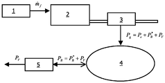
- the illustration firstly shows an internal combustion engine 2 which generates a mechanical power in a known manner by supplying a fuel mass flow ⁇ f from a fuel tank 1. A part of this mechanical power is picked up by a generator 3 (alternator), which is coupled to the crankshaft of the internal combustion engine 2, and converted into an electrical power P g .
- the electrical power P g is fed to the symbolically represented vehicle electrical system 4 of the motor vehicle. All electrical consumers are connected to the vehicle electrical system 4, the electrical power required by them being designated P e .
- a rechargeable accumulator battery 5 is also coupled to the vehicle electrical system 4, the electric power P B being exchanged between the vehicle electrical system 4 and the battery 5.
- the sign convention for the power P B is presently chosen so that when charging the battery P B > 0 and when discharging the battery P B ⁇ 0.
- the battery power P B consists of two parts: first, a reversible battery power P B *, which detects the proportion of energy which is 100% removable from the battery 5, and second, a battery L P V loss , which is irrevocably lost at each charge and discharge of the battery 5.
- variable power generation strategy of the generator 3 is proposed to improve fuel economy.
- This strategy consists of two parts, namely firstly an optimal charging strategy for a positive drive of the motor vehicle and secondly a strategy of regenerative braking when the mechanical brakes of the motor vehicle are active.
- the current operating point of the generator 3 is calculated using a chemical performance conversion optimization algorithm expressed as fuel mass flow ⁇ f with respect to the electrical power P g required by the electrical loads. In this optimization, it is decided whether the battery 5 is charged or discharged or whether no charge transfer with the battery 5 takes place at all.
- the said decision is made on the basis of a cost function J.
- the total power P g required by the electrical loads (including the battery 5) is measured.
- This total power P g must be generated by the generator 3, which leads to an additional fuel consumption of the internal combustion engine 2.
- the increase of the fuel mass flow ⁇ ⁇ f with respect to the normal, For the movement of the motor vehicle required fuel flow can be determined.
- BSFC Best is the best specific consumption value of the internal combustion engine
- n is the current rotational speed of the internal combustion engine 2
- T is the torque output by the internal combustion engine 2.
- the cost function is standardized from the best possible specific usage so that your value is always at least and at best one. The standardization allows a comparison between different internal combustion engines.
- the total power P g which is to be provided by the generator 3 to the on-board network 4, is composed of a power P B picked up by the battery 5 and a power P e picked up by the remaining electrical consumers.
- the battery losses P V occurring in the battery are measured during charging and discharging over a sliding time window and used to calculate the average charging and discharging efficiencies. The resulting average battery charging losses are thus continuously kept up to date.
- the total power P g can be varied and influence on the cost function J can be taken. This can in particular be exploited to push the overall performance as close as possible to a minimum of the cost function, ie the generation of electrical power to operate from fuel as efficiently as possible.
- the optimal value of the battery power belonging to such a minimum of the cost function is designated by P B, opt . This optimum value can be calculated by means of numerical approximation methods from the above contexts.
- a gear is preferably selected, which maximizes the energy flowing into the battery 5 energy.
Description
Die Erfindung betrifft ein Verfahren zur Regelung der elektrischen Batterieleistung, die der mit dem Bordnetz eines Kraftfahrzeuges gekoppelten Batterie des Kraftfahrzeuges zugeführt oder entnommen wird, wobei die vom Kraftfahrzeug verbrauchte elektrische Gesamtleistung von einem an die Brennkraftmaschine des Kraftfahrzeuges gekoppelten Generator erzeugt wird. Ferner betrifft die Erfindung einen Regler zur Durchführung eines derartigen Verfahrens.The invention relates to a method for regulating the electric battery power, which is supplied to or taken from the battery of the motor vehicle coupled to the electrical system of a motor vehicle, wherein the total electrical power consumed by the motor vehicle is generated by a generator coupled to the internal combustion engine of the motor vehicle. Furthermore, the invention relates to a controller for carrying out such a method.
An das elektrische Bordnetz eines Kraftfahrzeuges sind die elektrischen Verbraucher des Kraftfahrzeuges sowie in der Regel eine wiederaufladbare Batterie gekoppelt. Die dem Bordnetz entnommene elektrische Energie wird von einem Generator ("Lichtmaschine") erzeugt, welcher von der Brennkraftmaschine des Kraftfahrzeuges angetrieben wird. Die an das Bordnetz gekoppelte Batterie dient dazu, eine Energiereserve beziehungsweise einen Puffer zu bilden, um jederzeit ausreichend Leistung für z. B. das Anlassen der Brennkraftmaschine bereitzustellen.To the electrical system of a motor vehicle, the electrical consumers of the motor vehicle and usually a rechargeable battery are coupled. The electrical energy taken from the electrical system is generated by a generator ("alternator"), which is driven by the internal combustion engine of the motor vehicle. The coupled to the electrical system battery is used to form an energy reserve or a buffer to at any time sufficient power for z. B. to provide the starting of the internal combustion engine.
Die Versorgung des elektrischen Bordnetzes durch den Generator wird bei konventionellen Ladereglern derart geregelt, daß eine bestimmte Spannung oberhalb der Leerlaufspannung der Batterie eingestellt wird, um den Ladezustand der Batterie bei nahezu 100% zu halten. Auf diese Weise soll die Spannung im Bordnetz auf einem stationären Wert gehalten werden und stets ausreichend Energie für das Anlassen der Brennkraftmaschine zur Verfügung stehen. Unter dem Gesichtspunkt einer effizienten Energieausnutzung ist eine derartige Regelungsstrategie allerdings ungünstig, da hierbei sehr viel Energie in Gasreaktionen in der Batterie verloren geht. Auch ist ein Ladezustand von nahezu 100% bei Verwendung eines regenerativen Bremssystems nicht empfehlenswert, da die Batterie bei einem derartigen Ladezustand die beim regenerativen Bremsen freigesetzte elektrische Leistung kaum aufnehmen kann. Deshalb sind Batterieladesysteme vorgeschlagen worden, bei denen der Ladezustand in einem Fenster bzw. um einen Betriebspunkt herum gehalten wird, wobei das Fenster bzw. der Betriebspunkt deutlich unterhalb von 100 % liegt. Ein derartiges System ist beispielsweise aus der
Diese Aufgabe wird durch ein Verfahren mit den Merkmalen des Anspruchs 1 sowie durch einen Regler mit den Merkmalen des Anspruchs 6 gelöst.This object is achieved by a method having the features of
Vorteilhafte Ausgestaltungen sind in den Unteransprüchen enthalten.Advantageous embodiments are contained in the subclaims.
Das erfindungsgemäße Verfahren dient der Regelung der elektrischen Batterieleistung, worunter definitionsgemäß die elektrische Leistung verstanden wird, die einer mit dem Bordnetz eines Kraftfahrzeuges gekoppelten Batterie des Kraftfahrzeuges zugeführt oder entnommen wird. Per Konvention kann dabei z. B. eine der Batterie zugeführte Leistung einen positiven Wert und eine entnommene Leistung einen negativen Wert haben. Bei dem Verfahren wird die vom Kraftfahrzeug (d. h. Bordnetz einschließlich der Batterie) verbrauchte elektrische Gesamtleistung von einem an die Brennkraftmaschine des Kraftfahrzeuges gekoppelten Generator erzeugt. Das Verfahren ist dadurch gekennzeichnet, daß eine Kostenfunktion berechnet wird, deren Wert ein Maß für den Kraftstoffmehrverbrauch, der für die Erzeugung der elektrischen Gesamtleistung durch den Generator erforderlich ist, im Verhältnis zu der mit diesem Mehrverbrauch erzeugten Gesamtleistung wiedergibt. Mit Hilfe dieser Kostenfunktion wird dann ein Optimalwert der Batterieleistung derart bestimmt, daß der Wert der Kostenfunktion bei Einstellung des Optimalwertes ein Minimum annimmt.The method according to the invention serves to regulate the electrical battery power, which by definition is understood to mean the electric power that is supplied or removed from a battery of the motor vehicle coupled to the electrical system of a motor vehicle. By convention, z. B. a power supplied to the battery have a positive value and a power taken a negative value. In the method, the total electrical power consumed by the motor vehicle (ie electrical system including the battery) is generated by a generator coupled to the internal combustion engine of the motor vehicle. The method is characterized in that a cost function is calculated whose value reflects a measure of the additional fuel consumption required for the generation of the total electrical power by the generator in relation to the total power generated with this additional consumption. With the aid of this cost function, an optimum value of the battery power is then determined such that the value of the cost function assumes a minimum when setting the optimum value.
Die bei dem Verfahren verwendete Kostenfunktion spiegelt die Effizienz bzw. den Wirkungsgrad der Stromerzeugung wider, da diese den Kraftstoffverbrauch in Beziehung zu der damit erzeugten elektrischen Leistung setzt. Je kleiner der Wert der Kostenfunktion ist, desto effizienter wird der Kraftstoff in elektrische Energie umgewandelt.The cost function used in the method reflects the efficiency of power generation because it relates fuel consumption to electrical power generated therewith. The smaller the value of the cost function, the more efficiently the fuel is converted into electrical energy.
Die Abhängigkeit der Kostenfunktion von verschiedenen Zustandsgrößen und Parametern kann theoretisch hergeleitet und/oder empirisch ermittelt werden. Dabei zeigt es sich, daß unter gegebenen Rahmenbedingungen bei einem bestimmten Wert der erzeugten elektrischen Leistung die Kraftstoffausnutzung optimal, d. h. der Wert der Kostenfunktion minimal ist. Bei dem erläuterten Verfahren wird nun die Batterieleistung als einstellbarer Parameter behandelt, dessen Wert so bestimmt wird, daß die Kostenfunktion minimiert wird. Durch ein Laden der Batterie kann nämlich die verbrauchte Gesamtleistung des Bordnetzes erhöht und durch ein Entladen der Batterie verringert werden. Durch Veränderung der Batterieleistung kann somit die verbrauchte Gesamtleistung in einen Punkt verlagert werden, in dem die Kostenfunktion minimal ist. Die Bereitstellung elektrischer Energie für das Bordnetz erfolgt dann jederzeit unter optimaler Kraftstoffausnutzung.The dependence of the cost function on different state variables and parameters can be theoretically derived and / or determined empirically. It turns out that under given conditions at a certain value of the electrical power generated the fuel efficiency optimally, d. H. the value of the cost function is minimal. In the illustrated method, the battery power is now treated as an adjustable parameter whose value is determined so that the cost function is minimized. By charging the battery, namely, the consumed total power of the electrical system can be increased and reduced by discharging the battery. By changing the battery power, the total power consumed can thus be shifted to a point where the cost function is minimal. The supply of electrical energy for the electrical system is then at any time under optimal fuel efficiency.
Gemäß einer bevorzugten Ausgestaltung des Verfahrens werden bei der Bestimmung des Optimalwertes die Batterieladeverluste berücksichtigt. Batterieladeverluste entstehen aufgrund der realen physikalischen und chemischen Prozesse und lassen sich durch die Differenz zwischen der einer Batterie beim Laden zugeführten elektrischen Energie und der beim Entladen aus der Batterie wieder entnehmbaren Energie quantifizieren. Die Berücksichtigung der Batterieladeverluste erlaubt eine realistischere Optimierung der Stromerzeugung, da durch diese die Kosten für die Verwendung der Batterie als Puffer berücksichtigt werden.According to a preferred embodiment of the method, the battery charging losses are taken into account when determining the optimum value. Battery charging losses are due to the real physical and chemical processes and can be quantified by the difference between the electrical energy supplied to a battery during charging and the energy that can be taken out of the battery during discharge. The consideration of the battery charging losses allows a more realistic optimization of power generation, as it takes into account the costs of using the battery as a buffer.
Bei der vorstehend beschriebenen Ausführungsart des Verfahrens werden die Batterieladeverluste vorzugsweise durch eine laufende Mittelwertbildung der gemessenen Effizienz der Batterieladung und Batterieentladung bestimmt. Auf diese Weise werden die für die Batterieladeverluste relevanten Parameter ständig auf einem aktuellen Wert gehalten.In the above-described embodiment of the method, the battery charging losses are preferably determined by a running averaging of the measured efficiency of the battery charge and battery discharge. In this way, the parameters relevant for the battery charging losses are constantly kept at a current value.
Gemäß der Erfindung wird die tatsächlich eingestellte Batterieleistung gegenüber dem berechneten Optimalwert erhöht, falls der Ladezustand der Batterie niedriger als ein vorgegebener Wert ist, und verringert, falls der Ladezustand der Batterie höher als ein vorgegebener Wert ist. Durch diese Korrektur des Optimalwertes kann sichergestellt werden, daß ein gewünschter vorgegebener Wert für den Ladezustand der Batterie näherungsweise eingehalten wird, bzw. daß der Ladezustand der Batterie in einem vorgegebenen Fenster gehalten wird.According to the invention, the battery power actually set is increased from the calculated optimum value if the state of charge of the battery is lower than a predetermined value, and decreased if the state of charge of the battery is higher than a predetermined value. By this correction of the optimum value can be ensured that a desired predetermined value for the state of charge of the battery is approximately maintained, or that the state of charge of the battery is kept in a predetermined window.
Vorzugsweise wird das Verfahren durch eine Strategie zu einem regenerativen Bremsen des Kraftfahrzeuges ergänzt. Beim regenerativen Bremsen wird die Bremsenergie teilweise in elektrische Energie umgewandelt. Die in der Bewegung des Fahrzeuges gespeicherte kinetische Energie geht daher nicht ganz in Reibungswärme über - und somit der Energiebilanz verloren -, sondern wird überwiegend in nutzbare elektrische Energie verwandelt.Preferably, the method is supplemented by a strategy for a regenerative braking of the motor vehicle. In regenerative braking, the braking energy is partially converted into electrical energy. The stored in the movement of the vehicle kinetic energy is therefore not entirely in frictional heat - and thus the energy balance lost - but is mainly converted into usable electrical energy.
Das regenerative Bremsen wird dabei vorzugsweise in einem Gang durchgeführt, welcher die erzeugte elektrische Energie beziehungsweise den Energiefluß zur Batterie maximiert.The regenerative braking is preferably carried out in a gear which maximizes the generated electrical energy or the energy flow to the battery.
Die Erfindung betrifft ferner einen Regler zur Regelung der elektrischen Batterieleistung, die der mit dem Bordnetz eines Kraftfahrzeuges gekoppelten Batterie des Kraftfahrzeuges zugeführt oder entnommen wird, wobei die vom Kraftfahrzeug verbrauchte elektrische Gesamtleistung von einem an die Brennkraftmaschine des Kraftfahrzeuges gekoppelten Generator erzeugt wird. Der Regler ist dadurch gekennzeichnet, daß dieser dahingehend ausgebildet ist, ein Verfahren der vorstehend erläuterten Art durchzuführen. Der Regler kann somit eine Kostenfunktion berechnen, welche das Verhältnis des Kraftstoffmehrverbrauches zur damit erzeugten elektrischen Gesamtleistung bestimmt. Ferner kann der Regler einen Optimalwert der Batterieleistung derart bestimmen und einstellen, daß die genannte Kostenfunktion minimiert wird.The invention further relates to a controller for controlling the battery electric power, which is supplied to or taken from the battery of the motor vehicle coupled to the electrical system of a motor vehicle, wherein the total electrical power consumed by the motor vehicle is generated by a generator coupled to the internal combustion engine of the motor vehicle. The controller is characterized in that it is designed to perform a method of the type described above. The controller can thus be a cost function calculate, which determines the ratio of the additional fuel consumption to the total electrical power generated thereby. Further, the controller may determine and adjust an optimum value of the battery power so as to minimize said cost function.
Ein wesentlicher Aspekt der vorliegenden Erfindung besteht darin, daß für die Ladestrategie nicht nur der Ladezustand (SOC) der Batterie, der mittels verschiedener bekannter Verfahren näherungsweise z. B. anhand der Batteriespannung, der Batterietemperatur und der Batterieleistung bestimmt werden kann, herangezogen wird, sondern auch die Kraftstoffeffizienz der Energieerzeugung durch den Generator durch Einführung einer Kostenfunktion mit berücksichtigt wird. Dies führt z. B. dazu, daß im Leerlaufbetrieb des Verbrennungsmotors die elektrische Leistung verstärkt über die Batterie bereitgestellt wird, solange der Ladezustand der Batterie dies erlaubt, um die Kraftstoffeffizienz insgesamt zu erhöhen. Die in diesem Zustand entnommene Leistung wird der Batterie in energetisch effizienteren Betriebsbereichen des Generators oder bei einem generatorischen Bremsen wieder zugeführt. Trotz der Batterieladeverluste kann hierdurch in der Gesamtbilanz eine Kraftstoffersparnis erzielt werden.An essential aspect of the present invention is that for the charging strategy not only the state of charge (SOC) of the battery, by means of various known methods, approximately z. B. on the basis of the battery voltage, the battery temperature and the battery power can be determined is used, but also the fuel efficiency of the power generation by the generator by introducing a cost function is taken into account. This leads z. Example, that in the idle operation of the internal combustion engine, the electric power is provided via the battery reinforced, as long as the state of charge of the battery allows it to increase the overall fuel efficiency. The power taken in this condition is returned to the battery in more energetically efficient operating areas of the generator or during regenerative braking. Despite the battery charging losses, this can be achieved in the overall balance fuel savings.
Im Folgenden wird die Erfindung mit Hilfe der beigefügten Figur beispielhaft erläutert. Die einzige Abbildung zeigt die Systemkomponenten, die an der Durchführung des erfindungsgemäßen Verfahrens beteiligt sind.In the following the invention will be explained by way of example with the aid of the attached FIGURE. The single figure shows the system components involved in carrying out the method according to the invention.
Zu erkennen ist in der Abbildung zunächst eine Brennkraftmaschine 2, welche in bekannter Weise unter Zufuhr eines Kraftstoffmassenflusses ṁf aus einem Kraftstofftank 1 eine mechanische Leistung erzeugt. Ein Teil dieser mechanischen Leistung wird von einem Generator 3 (Lichtmaschine), der an die Kurbelwelle der Brennkraftmaschine 2 gekoppelt ist, abgegriffen und in eine elektrische Leistung Pg umgewandelt. Die elektrische Leistung Pg wird dem symbolisch dargestellten Bordnetz 4 des Kraftfahrzeuges zugeführt. An das Bordnetz 4 sind alle elektrischen Verbraucher angeschlossen, wobei die von diesen benötigte elektrische Leistung mit Pe bezeichnet wird.The illustration firstly shows an
An das Bordnetz 4 ist ferner eine wiederaufladbare Akkumulatorbatterie 5 angekoppelt, wobei zwischen dem Bordnetz 4 und der Batterie 5 die elektrische Leistung PB ausgetauscht wird. Die Vorzeichenkonvention für die Leistung PB ist vorliegend so gewählt, daß bei einem Laden der Batterie PB > 0 und bei einem Entladen der Batterie PB < 0 ist.A
Des Weiteren ist in der Abbildung erkennbar, daß sich die Batterieleistung PB aus zwei Teilen zusammensetzt: erstens einer reversiblen Batterieleistung PB *, die den Energieanteil erfaßt, welcher der Batterie 5 zu 100% wieder entnehmbar ist, und zweitens einem Batterieladeverlust PV , welcher bei jedem Lade- und Entladevorgang der Batterie 5 unwiderruflich verloren geht.Furthermore, it can be seen in the figure that the battery power P B consists of two parts: first, a reversible battery power P B *, which detects the proportion of energy which is 100% removable from the
Während herkömmliche Verfahren zur Kontrolle der Batterieladung eine konstante Spannung der Batterie 5 einzuhalten versuchen, wird vorliegend zur Verbesserung der Kraftstoffausnutzung eine Strategie mit einer variablen Stromerzeugung des Generators 3 vorgeschlagen. Diese Strategie besteht aus zwei Teilen, nämlich erstens aus einer optimalen Ladestrategie bei einem positiven Antrieb des Kraftfahrzeuges, und zweitens aus einer Strategie des regenerativen Bremsens, wenn die mechanischen Bremsen des Kraftfahrzeuges aktiv sind.While conventional battery charge control techniques attempt to maintain a constant voltage of the
Während der optimalen Ladestrategie wird der Strom-Betriebspunkt des Generators 3 mit einem Optimierungsalgorithmus für die Umwandlung chemischer Leistung, ausgedrückt als Kraftstoffmassenfluß ṁf in Bezug auf die von den elektrischen Lasten benötigte elektrische Leistung Pg , berechnet. Bei dieser Optimierung wird darüber entschieden, ob die Batterie 5 geladen oder entladen wird beziehungsweise ob überhaupt kein Ladungstransfer mit der Batterie 5 stattfindet.During the optimum charging strategy, the current operating point of the
Die genannte Entscheidung wird auf der Basis einer Kostenfunktion J getroffen. Dazu wird die von den elektrischen Lasten (einschließlich der Batterie 5) benötigte Gesamtleistung Pg gemessen. Diese Gesamtleistung Pg muß vom Generator 3 erzeugt werden, was zu einem Kraftstoffmehrverbrauch der Brennkraftmaschine 2 führt. Der Anstieg des Kraftstoffmassenflusses Δṁf in Bezug auf den normalen, für die Bewegung des Kraftfahrzeuges benötigten Kraftstofffluß kann ermittelt werden. Sodann kann die Kostenfunktion J berechnet werden als das Verhältnis von Kraftstoffmehrverbrauch zur Gesamtleistung gemäß: ![]()
![]()
Hierin ist BSFC Best der beste spezifische Verbrauchswert des Verbrennungsmotors, n die aktuelle Drehzahl der Brennkraftmaschine 2 und T das von der Brennkraftmaschine 2 abgegebene Drehmoment. Die Kostenfunktion wird vom besten möglichen spezifischen Verbrauch genormt, damit Ihr Wert immer mindestens und im besten Fall eins ist. Die Normierung erlaubt einen Vergleich zwischen verschieden Verbrennungsmotoren.Here, BSFC Best is the best specific consumption value of the internal combustion engine, n is the current rotational speed of the
Wie vorstehend erläutert, setzt sich die Gesamtleistung Pg , die vom Generator 3 an das Bordnetz 4 zur Verfügung zu stellen ist, aus einer von der Batterie 5 aufgenommenen Leistung PB und einer von den übrigen elektrischen Verbrauchern aufgenommenen Leistung Pe zusammen. Die Batterieleistung setzt sich wiederum aus einem reversiblen Anteil PB *, welcher ohne Verlust der Batterie wieder entnommen werden kann, und einem Batterieladeverlust PV zusammen, d.h.: ![]()
![]()
Die in der Batterie auftretenden Batterieverluste PV werden während des Ladens und des Entladens über ein gleitendes Zeitfenster gemessen und verwendet, um die durchschnittlichen Lade- und Entladeeffizienzen zu berechnen. Die hieraus erhaltenen durchschnittlichen Batterieladeverluste werden auf diese Weise kontinuierlich auf dem neuesten Stand gehalten.The battery losses P V occurring in the battery are measured during charging and discharging over a sliding time window and used to calculate the average charging and discharging efficiencies. The resulting average battery charging losses are thus continuously kept up to date.
Durch Veränderung der Batterieleistung PB kann die Gesamtleistung Pg variiert und damit Einfluß auf die Kostenfunktion J genommen werden. Dies kann insbesondere dazu ausgenutzt werden, die Gesamtleistung möglichst nahe an ein Minimum der Kostenfunktion zu schieben, d.h. die Erzeugung elektrischer Leistung aus Kraftstoff möglichst effizient zu betreiben. Der zu einem solchen Minimum der Kostenfunktion gehörende Optimalwert der Batterieleistung sei dabei mit PB,opt bezeichnet. Dieser Optimalwert kann mittels numerischer Näherungsmethoden aus den vorstehenden Zusammenhängen berechnet werden.By changing the battery power P B , the total power P g can be varied and influence on the cost function J can be taken. This can in particular be exploited to push the overall performance as close as possible to a minimum of the cost function, ie the generation of electrical power to operate from fuel as efficiently as possible. The optimal value of the battery power belonging to such a minimum of the cost function is designated by P B, opt . This optimum value can be calculated by means of numerical approximation methods from the above contexts.
Um einen vorgegebenen nominellen Ladezustand (SOC: state of Charge) der Batterie aufrecht zu erhalten, wird weiterhin noch eine Korrektur der berechneten optimalen Batterieleistung PB,opt vorgenommen. Wenn der gemessene aktuelle Ladezustand SOC der Batterie 5 geringer als der Ziel-SOC ist, wird die optimale Batterieleistung PB,opt erhöht. Wenn dagegen der aktuelle SOC oberhalb des Ziel-SOC liegt, wird die optimale Batterieleistung verringert.In order to maintain a predetermined nominal state of charge of the battery (SOC), a correction of the calculated optimal battery power P B, opt is still made. When the measured current state of charge SOC of the
Wenn das Kraftfahrzeug nicht angetrieben, sondern gebremst wird, wird in einer Strategie des regenerativen Bremsens Energie aus dem Bremsvorgang zurückgewonnen und in elektrische Energie umgewandelt. Dabei wird vorzugsweise ein Gang gewählt, welcher die in die Batterie 5 fließende Energie maximiert.When the motor vehicle is not driven but braked, in a regenerative braking strategy, energy is recovered from the braking process and converted into electrical energy. In this case, a gear is preferably selected, which maximizes the energy flowing into the
Claims (6)
- Method for controlling the electrical battery power which is supplied to or drawn from the battery (5) of a motor vehicle which is coupled to the power supply system (4) of the motor vehicle, the total electrical power (Pg) consumed by the motor vehicle being generated by a generator (3) which is coupled to the internal combustion engine (2) of the motor vehicle, wherein a cost function is calculated which represents a measure of the additional fuel consumption based on the total electrical power generated by this additional consumption, and that an optimal value for the battery power is determined such that the cost function is minimized,
characterized in that
the total power comprises a battery power (PB ) consumed by the battery (5) and a power (Pe ) consumed by the other electrical loads, wherein the set battery power is greater than or less than the calculated optimal value in order to keep the state of charge of the battery (5) within a predetermined value range. - Method according to Claim 1,
characterized in that
the battery charging losses (PV) are taken into account when determining the optimal value. - Method according to Claim 2,
characterized in that
the battery charging losses (PV) are determined by continually averaging the measured efficiency of the battery charging and battery discharging. - Method according to one of Claims 1 to 3,
characterized in that
regenerative braking of the motor vehicle is carried out in which the braking energy is converted at least partially to electrical energy. - Method according to Claim 4,
characterized in that
the regenerative braking is carried out in a gear which maximizes the generated electrical energy. - Controller for controlling the electrical battery power which is supplied to or drawn from the battery (5) of a motor vehicle which is coupled to the power supply system (4) of the motor vehicle, the total electrical power (Pg) consumed by the motor vehicle being generated by a generator (3) which is coupled to the internal combustion engine (2) of the motor vehicle,
characterized in that
the controller is designed to carry out a method according to at least one of Claims 1 to 5.
Priority Applications (2)
| Application Number | Priority Date | Filing Date | Title |
|---|---|---|---|
| EP02102591.1A EP1420497B1 (en) | 2002-11-15 | 2002-11-15 | Method for regulating battery power in a vehicle |
| US10/712,079 US20040135547A1 (en) | 2002-11-15 | 2003-11-13 | Method for controlling the electrical battery power in a motor vehicle |
Applications Claiming Priority (1)
| Application Number | Priority Date | Filing Date | Title |
|---|---|---|---|
| EP02102591.1A EP1420497B1 (en) | 2002-11-15 | 2002-11-15 | Method for regulating battery power in a vehicle |
Publications (2)
| Publication Number | Publication Date |
|---|---|
| EP1420497A1 EP1420497A1 (en) | 2004-05-19 |
| EP1420497B1 true EP1420497B1 (en) | 2018-06-20 |
Family
ID=32116319
Family Applications (1)
| Application Number | Title | Priority Date | Filing Date |
|---|---|---|---|
| EP02102591.1A Expired - Lifetime EP1420497B1 (en) | 2002-11-15 | 2002-11-15 | Method for regulating battery power in a vehicle |
Country Status (2)
| Country | Link |
|---|---|
| US (1) | US20040135547A1 (en) |
| EP (1) | EP1420497B1 (en) |
Families Citing this family (4)
| Publication number | Priority date | Publication date | Assignee | Title |
|---|---|---|---|---|
| DE102004063163A1 (en) * | 2004-12-29 | 2006-07-20 | Robert Bosch Gmbh | Method for determining the internal resistance of a battery |
| US20080288132A1 (en) * | 2007-05-16 | 2008-11-20 | General Electric Company | Method of operating vehicle and associated system |
| DE102010039041A1 (en) | 2010-08-09 | 2012-02-09 | Robert Bosch Gmbh | Method for operating a vehicle electrical system, control and computer program product |
| US9008874B2 (en) * | 2011-01-26 | 2015-04-14 | Toyota Motor Engineering & Manufacturing North America, Inc. | System and method for managing power in a vehicle |
Citations (1)
| Publication number | Priority date | Publication date | Assignee | Title |
|---|---|---|---|---|
| EP1199205A2 (en) * | 2000-09-22 | 2002-04-24 | Nissan Motor Co., Ltd. | Control system for hybrid vehicle |
Family Cites Families (4)
| Publication number | Priority date | Publication date | Assignee | Title |
|---|---|---|---|---|
| EP0937327A1 (en) * | 1996-11-08 | 1999-08-25 | AlliedSignal Inc. | Vehicular power management system and method |
| US5820172A (en) * | 1997-02-27 | 1998-10-13 | Ford Global Technologies, Inc. | Method for controlling energy flow in a hybrid electric vehicle |
| US6091228A (en) * | 1998-04-29 | 2000-07-18 | Lockheed Martin Corp. | Control system for, in the presence of a varying system load, establishing generator current to maintain a particular battery charge state |
| US6166523A (en) * | 2000-01-11 | 2000-12-26 | Honeywell International Inc. | Smart alternator method and apparatus for optimizing fuel efficiency and monitoring batteries in an automobile |
-
2002
- 2002-11-15 EP EP02102591.1A patent/EP1420497B1/en not_active Expired - Lifetime
-
2003
- 2003-11-13 US US10/712,079 patent/US20040135547A1/en not_active Abandoned
Patent Citations (1)
| Publication number | Priority date | Publication date | Assignee | Title |
|---|---|---|---|---|
| EP1199205A2 (en) * | 2000-09-22 | 2002-04-24 | Nissan Motor Co., Ltd. | Control system for hybrid vehicle |
Also Published As
| Publication number | Publication date |
|---|---|
| US20040135547A1 (en) | 2004-07-15 |
| EP1420497A1 (en) | 2004-05-19 |
Similar Documents
| Publication | Publication Date | Title |
|---|---|---|
| DE60103195T2 (en) | Device for controlling the warm-up of a hybrid vehicle | |
| EP1325542B1 (en) | Method for regulating the generator voltage in a motor vehicle | |
| DE60103093T2 (en) | Regeneration control device in a hybrid electric vehicle | |
| EP3351472B1 (en) | Device for providing electrical energy for an electrical consumer and/or for charging a battery in a boat | |
| EP1814754B1 (en) | Method for controlling an operation of a hybrid motor vehicle and hybrid vehicle | |
| DE102006001201B4 (en) | Method for controlling a battery charging operation | |
| DE10121962A1 (en) | Energy management system for motor vehicle on-board electrical system controls energy distribution taking into account current generation, storage, consumption component efficiencies | |
| WO1998034022A1 (en) | Propulsion system, especially automotive, and method for frustrating a change of the idling speed in such a system | |
| EP1676738A2 (en) | Method and apparatus for control of hybrid energy storage in a hybrid vehicle | |
| DE102005044268A1 (en) | Energy storage/energy flow`s charge state controlling or regulating method for use in vehicle, involves controlling or regulating charge state of energy storage/flow depending on cost function for energy consumption or emission output | |
| DE102011008247B4 (en) | Control algorithm for low voltage switching in hybrid and conventional vehicles | |
| EP1673251A1 (en) | Method for regulation of the state of charge of an energy store on a vehicle with hybrid drive | |
| DE102005046342B4 (en) | Method for controlling an output voltage of a generator | |
| EP1991453B1 (en) | Method for operating a hybrid vehicle, and control unit for carrying out the method | |
| WO2008015049A1 (en) | Apparatus for controlling a hybrid drive | |
| EP1420497B1 (en) | Method for regulating battery power in a vehicle | |
| WO2004106104A1 (en) | Motor vehicle and associated electronic control device | |
| DE112011103152T5 (en) | Device for power control of an internal combustion engine | |
| EP1523083A1 (en) | Voltage Supply System in a vehicle having a Dual-Voltage Power Supply Circuit and Method for Supplying such Power Supply Circuit | |
| DE102008019683A1 (en) | Rail vehicle and method for reducing the fuel consumption of a rail vehicle | |
| DE102022117000A1 (en) | battery charge manager | |
| DE102008041027A1 (en) | On-board electrical system for a motor vehicle | |
| EP1531074B1 (en) | Hybrid vehicle with cruise control system | |
| DE102016219614A1 (en) | Motor vehicle with internal combustion engine and method for operating a motor vehicle with internal combustion engine | |
| DE102006014401A1 (en) | Method for controlling power take-up from engine by generators during e.g. braking comprises measuring instantaneous operating parameters, deriving desired take-up and comparing actual instantaneous values with this to control take up |
Legal Events
| Date | Code | Title | Description |
|---|---|---|---|
| PUAI | Public reference made under article 153(3) epc to a published international application that has entered the european phase |
Free format text: ORIGINAL CODE: 0009012 |
|
| AK | Designated contracting states |
Kind code of ref document: A1 Designated state(s): AT BE BG CH CY CZ DE DK EE ES FI FR GB GR IE IT LI LU MC NL PT SE SK TR |
|
| AX | Request for extension of the european patent |
Extension state: AL LT LV MK RO SI |
|
| 17P | Request for examination filed |
Effective date: 20041119 |
|
| AKX | Designation fees paid |
Designated state(s): DE FR GB |
|
| 17Q | First examination report despatched |
Effective date: 20170307 |
|
| GRAP | Despatch of communication of intention to grant a patent |
Free format text: ORIGINAL CODE: EPIDOSNIGR1 |
|
| RAP1 | Party data changed (applicant data changed or rights of an application transferred) |
Owner name: FORD GLOBAL TECHNOLOGIES, LLC |
|
| INTG | Intention to grant announced |
Effective date: 20180202 |
|
| GRAS | Grant fee paid |
Free format text: ORIGINAL CODE: EPIDOSNIGR3 |
|
| GRAA | (expected) grant |
Free format text: ORIGINAL CODE: 0009210 |
|
| RAP1 | Party data changed (applicant data changed or rights of an application transferred) |
Owner name: FORD GLOBAL TECHNOLOGIES, LLC |
|
| AK | Designated contracting states |
Kind code of ref document: B1 Designated state(s): DE FR GB |
|
| REG | Reference to a national code |
Ref country code: GB Ref legal event code: FG4D Free format text: NOT ENGLISH |
|
| REG | Reference to a national code |
Ref country code: DE Ref legal event code: R096 Ref document number: 50216292 Country of ref document: DE |
|
| REG | Reference to a national code |
Ref country code: FR Ref legal event code: PLFP Year of fee payment: 17 |
|
| RIC2 | Information provided on ipc code assigned after grant |
Ipc: H02J 7/14 20060101AFI20030813BHEP |
|
| REG | Reference to a national code |
Ref country code: DE Ref legal event code: R097 Ref document number: 50216292 Country of ref document: DE |
|
| PLBE | No opposition filed within time limit |
Free format text: ORIGINAL CODE: 0009261 |
|
| STAA | Information on the status of an ep patent application or granted ep patent |
Free format text: STATUS: NO OPPOSITION FILED WITHIN TIME LIMIT |
|
| 26N | No opposition filed |
Effective date: 20190321 |
|
| PGFP | Annual fee paid to national office [announced via postgrant information from national office to epo] |
Ref country code: DE Payment date: 20211013 Year of fee payment: 20 Ref country code: GB Payment date: 20211028 Year of fee payment: 20 |
|
| PGFP | Annual fee paid to national office [announced via postgrant information from national office to epo] |
Ref country code: FR Payment date: 20211025 Year of fee payment: 20 |
|
| REG | Reference to a national code |
Ref country code: DE Ref legal event code: R071 Ref document number: 50216292 Country of ref document: DE |
|
| REG | Reference to a national code |
Ref country code: GB Ref legal event code: PE20 Expiry date: 20221114 |
|
| PG25 | Lapsed in a contracting state [announced via postgrant information from national office to epo] |
Ref country code: GB Free format text: LAPSE BECAUSE OF EXPIRATION OF PROTECTION Effective date: 20221114 |