EP0953198B1 - Electromechanical device and insulation method thereof - Google Patents
Electromechanical device and insulation method thereof Download PDFInfo
- Publication number
- EP0953198B1 EP0953198B1 EP98906874A EP98906874A EP0953198B1 EP 0953198 B1 EP0953198 B1 EP 0953198B1 EP 98906874 A EP98906874 A EP 98906874A EP 98906874 A EP98906874 A EP 98906874A EP 0953198 B1 EP0953198 B1 EP 0953198B1
- Authority
- EP
- European Patent Office
- Prior art keywords
- housing
- components
- expanding
- foam
- mechanical elements
- Prior art date
- Legal status (The legal status is an assumption and is not a legal conclusion. Google has not performed a legal analysis and makes no representation as to the accuracy of the status listed.)
- Expired - Lifetime
Links
Images

Classifications
-
- F—MECHANICAL ENGINEERING; LIGHTING; HEATING; WEAPONS; BLASTING
- F03—MACHINES OR ENGINES FOR LIQUIDS; WIND, SPRING, OR WEIGHT MOTORS; PRODUCING MECHANICAL POWER OR A REACTIVE PROPULSIVE THRUST, NOT OTHERWISE PROVIDED FOR
- F03G—SPRING, WEIGHT, INERTIA OR LIKE MOTORS; MECHANICAL-POWER PRODUCING DEVICES OR MECHANISMS, NOT OTHERWISE PROVIDED FOR OR USING ENERGY SOURCES NOT OTHERWISE PROVIDED FOR
- F03G7/00—Mechanical-power-producing mechanisms, not otherwise provided for or using energy sources not otherwise provided for
- F03G7/06—Mechanical-power-producing mechanisms, not otherwise provided for or using energy sources not otherwise provided for using expansion or contraction of bodies due to heating, cooling, moistening, drying or the like
- F03G7/061—Mechanical-power-producing mechanisms, not otherwise provided for or using energy sources not otherwise provided for using expansion or contraction of bodies due to heating, cooling, moistening, drying or the like characterised by the actuating element
- F03G7/06112—Mechanical-power-producing mechanisms, not otherwise provided for or using energy sources not otherwise provided for using expansion or contraction of bodies due to heating, cooling, moistening, drying or the like characterised by the actuating element using the thermal expansion or contraction of enclosed fluids
- F03G7/06113—Mechanical-power-producing mechanisms, not otherwise provided for or using energy sources not otherwise provided for using expansion or contraction of bodies due to heating, cooling, moistening, drying or the like characterised by the actuating element using the thermal expansion or contraction of enclosed fluids the fluids subjected to phase change
Definitions
- the present invention refers to an electromechanical device, such as for instance an actuator device, as defined in the preamble of Claim 1, and to a method to insulate components of an electromechanical device from the environment, as defined in the preamble of Claim 22; the features of the preamble of said claims are known for instance from BE-A-542.149, which describes a manual safety switch.
- Electromechanical devices which comprise a housing within which electrical components and movable mechanical elements or kinematic motions are contained, often near to each other. Let us think for instance of electrothermal actuator devices applied in various fields, including domestic appliances and environment air conditioning.
- Said electrothermal devices usually comprise an external housing, for example in thermoplastic material, wherein a thermoactuator and at least partially a movable operating shaft are contained.
- thermoactuator comprises a body made of electrically and thermally conductive material (for instance steel), containing a thermally expansible material (such as for instance wax), wherein a sliding thruster element is embedded. Said body is in contact with an electric heater, typically consisting of a resistor with a positive temperature coefficient (PTC), which is electrically supplied by two terminals.
- PTC positive temperature coefficient
- the heater When electric voltage is supplied to the supply terminals, the heater generates heat and causes the expansion of the thermally expansible material. Such an expansion causes the thruster to make a linear displacement outside the thermoactuator body; the thrust generated by the thruster is therefore transferred to the above shaft that will move linearly till it reaches a stable work position, generally determined by a mechanical limit stop, provided inside the housing of device.
- the heater cools down and the thermoexpansible material will shrink causing both the thruster and the shaft to go back to their initial rest positions, respectively, with the aid of an elastic return element, such as a spring.
- the present invention basically acknowledges that, in some applications, the electric components of certain electromechanical devices may be subject to malfunction risks, due to the aggressive influence of external agents in the environment.
- thermoelectric actuators are used in air conditioning or air cleaning systems, where the air to be conveyed or cleaned contains aggressive agents or contaminant substances, which may favour a development of electric discharges or electric energy leakages, overabsorptions or short-circuits with ensuing faults of the device itself.
- thermoelectric actuators may be located near water and/or detergent agent dispensers, whose likely losses might cause the above contamination with damaging effects for the device.
- the housings of the actuator devices of the type commonly used are not fit as such to warrant such a sealing from the environment, due to the presence of openings needed for the outcoming of movable mechanical components or of fissures due to an imperfect coupling of the external shells of the housing (to this purpose it should be noted that such components are commonly subject to shrinkage and/or stresses during the molding cycle of thermoplastic material).
- a first difficulty for instance, is due to the need of fully coating the electrical components of the device, but without any interference with the motion of the mechanical elements located nearby.
- a further difficulty consists in ensuring a fast filling (normally in the order of a few seconds) of the area to be insulated in order to allow for an automated manufacturing process.
- the filling material should also set very quickly to allow immediate handling of the device and avoid leakage from the joining areas of the relevant housing.
- said filling material should be easily removable in case of accidental leaking from the housing during the injection operation.
- thermoactuators normally reach about 200°C.
- thermoactuator which reflects a whole number of unfavorable characteristics for the use of classic filling and/or insulating materials, as mentioned hereafter.
- other fluid resins are injected at high temperature in a body or mold, where they set fast while cooling down; other resins are mixed at room temperature with a catalyst element suitable to determine a fast setting of the resin; further types of resins are also injected at room temperature and hardened by external heat or ultraviolet rays.
- Said resins may initially appear as a fluid or viscous material, which becomes a very hard glassy material following reticulation or transformation process.
- thermoactuator As already mentioned, resins with a low working temperature cannot be employed for a thermoactuator, as they would be degraded by the high temperature of the heating elements.
- resins generally have a highly compact volume tending to stick or block all components they come in contact with; even in case of very small metering errors of the injected material, there would be some jamming up risks for the movable actuation elements or kinematic motions inside the housing of the device.
- the use of fast setting silicones would be theoretically possible; however, in this case, the injected silicone would not have enough time to fully enter the housing section (usually of complex geometry) containing the live electric components, i.e. subject to electric voltage; therefore the insulation of such components from the environment would not be warranted.
- the volume of the filling material - as a function of its thermal characteristics - may act as a temperature dissipator or thermal flywheel, thus badly affecting the operating precision of the device; for example, in the case of a resin having a high thermal dissipation capacity, the heating times of a thermoactuator would be extended with a globally slower reaction of the device.
- Insulating materials of the expanding type are also known, which are used for instance for the purposes of refrigerators insulation or sealing of tubes for electric wires within buildings or for protecting from vibration electronic control units on motor-vehicles; said expanding materials are used, anyway, for the insulation of devices that are not equipped with movable mechanical elements.
- Said object is reached according to the present invention by introducing in the housing of the electromechanical device an insulating material suitable to form a spongy or foamy structure, therefore an elastic one, having a lower resistance to mechanical compression and/or to tensile stresses, thus allowing motion of the various elements; moreover, said structure can be easily broken and removed for easy cleaning of the residues eventually run out of the housing.
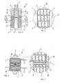
- Figs. 1, 2 and 3 show a thermal actuator device in a substantially known embodiment, of the type capable of impressing a thrust to an interlocked element (not represented), such as a flap of an air ventilation or purification system, a valve for hydraulic ducts, a detergent dispenser for household appliances, etc.
- an interlocked element such as a flap of an air ventilation or purification system, a valve for hydraulic ducts, a detergent dispenser for household appliances, etc.
- Such an actuator device indicated as a whole with 1 comprises an external housing 2, obtained for instance by the mutual engagement of two half-shelves 2A and 2B in thermoplastic material.
- the housing 2 has an opening on one of its lengthwise ends (the figure shows the upper end), wherefrom a part of an operating shaft 3 is protruding outside.
- a flanged part 4 is present, with holes 5, which allows the device 1 to be fastened by screws to a fixed part of the apparatus on which the device itself will be used.
- Number 6 indicates two side openings of the housing 2, provided for air recirculation, in order to speed up the cooling stage of a thermal element, as described in the following.
- Number 6A indicates an opening provided for allowing the introduction of an insulating material in the housing 2, according to the present invention.
- a thermal actuator indicated with 7, not sectioned in the figure, having a relevant thrusting element or small piston 8 is located inside the body 2; an end of piston 8 is confined inside the body of the thermoactuator 7, whereas the other end comes out of it to operate by thrust on the actuating shaft 3.
- thermoactuator 7 is made integral with the housing 2 in a known manner, within which also the shaft 3 is at least partially housed.
- the shaft 3 is movable under the action of the small piston 8, contrasting the action of a spring 9; said spring 9 is located inside the housing 2, between its upper portion and an enlargement 3A of the shaft 3; as it can be seen, an end of the shaft 3 is in contact with the small piston 8, whereas the opposite end protrudes out of said upper opening of the housing 2.
- Number 10 indicates a heating element for the thermoactuator 7, such as a thermistor with positive temperature coefficient, or PTC; numbers 11 and 12 indicate the electric supply terminals, respectively.
- terminals 11 and 12 have each one a portion that appears to be located inside the housing 2; such inner parts of terminals 11 and 12 are fitted with respective contact foils with the heating element 10 and the body of the thermoactuator 7, which consists of an electrically and thermally conductive material. Thus, electric continuity can be determined between the terminal 12, the thermoactuator 7 and the heating element 10.
- Number 13 indicates striker elements defined in the upper inner portion of the housing 2, whose function is to provide mechanical limit stops to the shaft motion 3.
- number 14 indicates supports made with the same plastic material used for the housing 2, whose task is to define a positioning seat for the thermoactuator 7.
- the device 1 is of known type and operation, as described at the beginning of this description. Therefore, if a supply signal is transmitted to terminals 11 and 12, the heating element 10 will generate heat, which is transferred to the body of the thermoactuator 7, to cause the expansion of a thermoexpandible material (wax) contained inside it.
- wax thermoexpandible material
- thermoactuator 7 causes a position change between the shaft 3 and the housing 2.
- the device 1 its live elements (i.e. those being subject to electric voltage) could be conveniently insulated from the environment, whenever the latter contains some agents that may develop electric discharges or electric energy leakages, overabsorptions or short-circuits, with a consequent risk of permanent damages to the actuator device.
- terminals 11 and 12 located outside the housing 2 Such a problem does not generally exist for the part of terminals 11 and 12 located outside the housing 2; such terminals are in fact sufficiently apart from each other and they can be well insulated through a proper protecting sheath.
- thermoactuator 7 insulation is a critical problem for the electric parts inside the housing 2, i.e. for the internal part of terminals 11 and 12, heater 10 and body of the thermoactuator 7:
- the body of the thermoactuator 7 is fully live (electrically conductive) and that the heater 10 has a highly reduced thickness (PTC thickness in this kind of applications is typically about 2-3 millimeters); therefore, the undesired deposition of an electrically conductive agent on the PTC, such as a salty mist or air suspended residues, may cause an electric discharge between the terminal 11 and the body of the thermoactuator 7, supplied by the terminal 12, with a consequent short-circuit and failure of the heater itself.
- the deposition of aggressive agents on live elements may cause electric energy leakages or overabsorptions, which are obviously affecting the operating properties of the device.
- PTCs usually have a metallization obtained with silver based alloys on its two opposite flat. surfaces; the material of said metallization under high environment humidity and the action of electric fields tends to migrate towards the heater edges, thus reducing the electric insulating distance.
- the required insulation is obtained introducing in the housing 2, through the opening 6A, a material suitable to form a spongy structure, having a low resistance to mechanical tensile stresses and compressions, as well as capable of withstanding high temperatures; such a material can favorably consists of an expanding silicone elastomer, i.e. a type suitable to form a foam.
- Figs 4 and 6 represent in fact, with two sections, an actuator device according to the present invention. It should be noted, anyway, that the device of Figs. 4 and 6 corresponds. in practice to the one of Figs. 1-3, but with addition of the above insulating material. To this purpose it should be underlined how the insulating operation from the environment according to the present invention can be obtained with all the components of the device 1 already arranged inside the housing 2 (i.e. with the device already assembled and eventually already submitted to a first testing).
- Said insulating material may consist for instance of SILBIONE®, manufactured by the Company Rhône-Poulenc, which is a silicone elastomer capable of curing or vulcanizing at room temperature, by a polyadditition in equal ratio of two components (being commercially known with codes RTV 72572 A and RTV 72572 B), and forming a rubber foam; such a foam is highly elastic and has a low mechanical resistance, so that it can be compressed and torn by very low mechanical forces. This notwithstanding, said foam is extremely resistant to high operating temperatures and has excellent electric insulating features.
- SILBIONE® manufactured by the Company Rhône-Poulenc
- Said silicone elastomer consisting of two components, having in particular a 1:1 mixing ratio, allows the use of a simple static mixer for injection in the housing 2.
- Said static mixer can for instance consist of a small thermoplastic tube, with internal labyrinths determining cross passages between the two flows of the components of the elastomer; said mixer has an extremely low cost and can be easily replaced on the manufacturing equipments.
- Both fluid components of the elastomer are injected in a known way through the opening 6A into the housing 2 of the actuator device 1; when said two components come in contact and mix together, they develop a gas capable of causing expansion and reticulate to form a flexible foam, indicated with S in the figure, having self-lubricating properties.
- the two components are in fluid form and reticulate after about 40 seconds following their mutual contact or mixing; therefore, during the injection stage there is all the time required to let the fluid mixture enter the parts involved of the housing 2, to safely coat all electric components, specifically the body of the thermoactuator 7, the heater 10 and the internal part of terminals 11 and 12; it should also be noted that the time required to obtain foam S is about one minute.
- Figs. 4 and 6 show a situation where the foam S is already formed; as it can be noted, after reticulation of the two cited components, the foam S completely fills the lower portion of the device, where the electric components to be insulated are located; from Fig. 4 it can also be noted how the foam S also covers a section of the shaft 3 and the spring 9, i.e. the movable mechanical elements of the device 1.
- the spongy structure formed by the silicone elastomer is of the netting type, i.e. defining a plurality of cells, some of them being indicated with C.
- the presence of such a netting structure allows an easy compressibility of the foam, so as any stress within the device 1 is avoided; said netting structure also causes the foam S to be substantially 'neutral' from the temperature standpoint, in other words, the foam does not operate as a thermal dissipator or flywheel.
- Fig. 8 the device 1 is represented after one actuation, which substantially consists in supplying power to terminals 11 and 12; as previously described, the heater 10 will heat the thermoexpandible material contained in the body of the thermoactuator 7, so that the thruster 8 comes out of it; therefore the thrust is transferred to the shaft 3 contrasting the action of the spring 9, till it reaches its limit stop position, which is maintained if power is supplied to terminals 11 and 12.
- the enlarged section 3A of the shaft 3 divides practically the foam S in two portions, namely an upper portion (which was originally formed on the top of section 3A) and a lower portion in the lower section of the housing 2, which will insulate a part of the terminals 11 and 12, the heater 10 and the thermoactuator 7.
- the portion of excess foam is easily 'torn away' from the portion provided for the real and proper insulation, and then simply compressed by the thrust imparted to the shaft 3.
- said features will prevent a clogging risk of the device, since the excess or useless portion of foam S depositing on the movable elements can be torn and/or compressed by the same elements without affecting the operation of the device.
- the housing 2 may have some side openings (6) or more simply some possible runways for the elastomer components (for instance fissures in the joining points of the half-shells 2A and 2B forming the housing 2).
- foam S can be removed in a simple and fast manner, due to its feature of limited resistance to tearing; for this reason its removal can take place by simple brushing of the housing 2.
- an electromechanical device can be provided, wherein insulation of certain components from the environment is possible, without affecting however the general operation of the device and/or causing a complex, time-taking or expensive industrial production.
- Such an insulating material appears to be specifically suitable for either small or wide motions of mechanical elements of the device; specifically, small movements are allowed due to the high elasticity and compressibility of the material, whereas wide motions are allowed by the possibility of partial removals/tearings of the material itself, as previously described.
- the mechanical elements of the device can easily torn and compress said material, restoring the various original sliding or motion seats; such a removal can also take place by lower forces, since the material structure allows for an easy tearing; a likely presence of movable residues of the torn filling material does not cause any inconveniences, since they are insulating, self-lubricating, compressible and further crumbling.
- the present invention has the following advantages:
- the device according to the present invention may comprise electric and mechanical apparatuses for movement in general, though not necessarily including an actuating element inside; on the other hand, the actuating elements may be of different type from the ones described by way of example, such as for instance an electromagnet or motor, etc.; while the electric parts may obviously comprise electronic or electromagnetic circuits, etc.
Landscapes
- Engineering & Computer Science (AREA)
- Chemical & Material Sciences (AREA)
- Combustion & Propulsion (AREA)
- Mechanical Engineering (AREA)
- General Engineering & Computer Science (AREA)
- Thermally Actuated Switches (AREA)
- Insulation, Fastening Of Motor, Generator Windings (AREA)
- Organic Insulating Materials (AREA)
- Casings For Electric Apparatus (AREA)
- Electrical Discharge Machining, Electrochemical Machining, And Combined Machining (AREA)
- Coupling Device And Connection With Printed Circuit (AREA)
Applications Claiming Priority (3)
| Application Number | Priority Date | Filing Date | Title |
|---|---|---|---|
| ITTO970026 | 1997-01-15 | ||
| IT97TO000026A IT1291014B1 (it) | 1997-01-15 | 1997-01-15 | Dispositivo elettromeccanico e relativo metodo di isolamento |
| PCT/EP1998/000179 WO1998032141A1 (en) | 1997-01-15 | 1998-01-14 | Electromechanical device and insulation method thereof |
Publications (2)
| Publication Number | Publication Date |
|---|---|
| EP0953198A1 EP0953198A1 (en) | 1999-11-03 |
| EP0953198B1 true EP0953198B1 (en) | 2002-12-18 |
Family
ID=11415217
Family Applications (1)
| Application Number | Title | Priority Date | Filing Date |
|---|---|---|---|
| EP98906874A Expired - Lifetime EP0953198B1 (en) | 1997-01-15 | 1998-01-14 | Electromechanical device and insulation method thereof |
Country Status (8)
| Country | Link |
|---|---|
| US (1) | US6240728B1 (it) |
| EP (1) | EP0953198B1 (it) |
| AU (1) | AU6292798A (it) |
| BR (1) | BR9812418A (it) |
| DE (1) | DE69810266T2 (it) |
| ES (1) | ES2189136T3 (it) |
| IT (1) | IT1291014B1 (it) |
| WO (1) | WO1998032141A1 (it) |
Families Citing this family (8)
| Publication number | Priority date | Publication date | Assignee | Title |
|---|---|---|---|---|
| ITTO20010756A1 (it) | 2001-07-31 | 2003-01-31 | Eltek Spa | Disposivito di attuazione di tipo termico. |
| ITTO20020709A1 (it) * | 2002-08-07 | 2004-02-08 | Eltek Spa | Dispositivo attuatore elettro-termico. |
| ITTO20031038A1 (it) | 2003-12-24 | 2005-06-25 | Eltek Spa | Dispositivo attuatore elettro-termico. |
| ES2378551T3 (es) * | 2004-10-21 | 2012-04-13 | Christensen Horn, Irene Karoline | Dispositivo de ventilación |
| FR2956450B1 (fr) * | 2010-02-12 | 2013-07-26 | Airbus Operations Sas | Actionneur thermique |
| FR2959533B1 (fr) * | 2010-05-03 | 2012-07-06 | Vernet | Element thermostatique et dispositif comprenant un tel element thermostatique |
| IT1400623B1 (it) | 2010-06-18 | 2013-06-14 | Eltek Spa | Dispositivo blocco porta per elettrodomestici con attuatore termico. |
| IT1402674B1 (it) | 2010-11-08 | 2013-09-13 | Eltek Spa | Dispositivo bloccoporta per elettrodomestici e meccanismo bistabile |
Family Cites Families (10)
| Publication number | Priority date | Publication date | Assignee | Title |
|---|---|---|---|---|
| BE542149A (it) * | ||||
| DE1276780B (de) * | 1964-09-11 | 1968-09-05 | Werner Kerber | Druckschalter, insbesondere fuer Fussbetaetigung |
| FR2217784B1 (it) * | 1973-02-09 | 1976-05-14 | Milly Lucien | |
| WO1983002525A1 (en) * | 1982-01-14 | 1983-07-21 | SAKAMOTO, Yoshiaki; | Switch |
| US5020325A (en) * | 1990-02-13 | 1991-06-04 | Procedes Vernet | Heat motor |
| US5263324A (en) * | 1991-09-30 | 1993-11-23 | Design & Manufacturing Company | Rotary electrothermal actuator |
| IT235022Y1 (it) * | 1994-05-20 | 2000-03-31 | Zanussi Elettrodomestici | Apparecchio frigorifero o congelatore con pannello anti-scoppio |
| KR100199844B1 (ko) * | 1994-10-31 | 1999-06-15 | 배길훈 | 형상기억합금을 이용한 유압펌프 |
| US5666810A (en) * | 1994-12-12 | 1997-09-16 | Chrysler Corporation | Electro-thermal actuator system |
| DE4444685A1 (de) * | 1994-12-15 | 1996-06-20 | Behr Thomson Dehnstoffregler | Thermostatisches Arbeitselement mit einem elektrischen Widerstandsheizelement |
-
1997
- 1997-01-15 IT IT97TO000026A patent/IT1291014B1/it active IP Right Grant
-
1998
- 1998-01-14 DE DE69810266T patent/DE69810266T2/de not_active Expired - Lifetime
- 1998-01-14 ES ES98906874T patent/ES2189136T3/es not_active Expired - Lifetime
- 1998-01-14 AU AU62927/98A patent/AU6292798A/en not_active Abandoned
- 1998-01-14 US US09/341,439 patent/US6240728B1/en not_active Expired - Lifetime
- 1998-01-14 WO PCT/EP1998/000179 patent/WO1998032141A1/en not_active Ceased
- 1998-01-14 EP EP98906874A patent/EP0953198B1/en not_active Expired - Lifetime
- 1998-01-14 BR BR9812418-8A patent/BR9812418A/pt not_active Application Discontinuation
Also Published As
| Publication number | Publication date |
|---|---|
| ES2189136T3 (es) | 2003-07-01 |
| BR9812418A (pt) | 2000-09-05 |
| EP0953198A1 (en) | 1999-11-03 |
| US6240728B1 (en) | 2001-06-05 |
| WO1998032141A1 (en) | 1998-07-23 |
| AU6292798A (en) | 1998-08-07 |
| DE69810266T2 (de) | 2003-09-04 |
| DE69810266D1 (de) | 2003-01-30 |
| ITTO970026A1 (it) | 1998-07-15 |
| IT1291014B1 (it) | 1998-12-14 |
Similar Documents
| Publication | Publication Date | Title |
|---|---|---|
| EP0953198B1 (en) | Electromechanical device and insulation method thereof | |
| GB2222323A (en) | Sealed electrical cable connector for use in oil wells | |
| EP1611305B1 (en) | Lock device with shape memory actuating means | |
| KR970051595A (ko) | 고압 스윗치 | |
| CN103069528A (zh) | 电路断路器极柱部件和用于制造该极柱部件的方法 | |
| CN103069527B (zh) | 制造电路断路器极柱部件的方法 | |
| US6644619B2 (en) | Valve housing with embedded electrical leads | |
| US7652553B2 (en) | Thermally activated electrical interrupt switch | |
| ITTO980671A1 (it) | Dispositivo di attuazione bistabile. | |
| KR20020004831A (ko) | 전기 가열이 가능한 작동부재를 구비한 서모스탯 밸브 | |
| US2727120A (en) | Electric heaters | |
| EP1606857B1 (en) | Constructional unit and method for the production thereof | |
| US20040258129A1 (en) | Dishwasher safe thermometer | |
| US8245510B2 (en) | Electro-thermal actuator device | |
| US6418359B1 (en) | Control device, especially a temperature control device such as a room temperature control device | |
| US4927988A (en) | Enclosed switch contact assembly | |
| KR20220153072A (ko) | 보상 요소를 구비한 밸브 | |
| CN85108787A (zh) | 用于内燃机防护的压力补偿温度开关装置 | |
| US4236135A (en) | Sealed motor protector | |
| KR100273918B1 (ko) | 누전방지형 열작동밸브와 밸브구동유니트 | |
| EP1394408B1 (en) | Electro-thermal actuation device | |
| WO2004019360A1 (en) | Method and apparatus for actuating a switching device using magnets | |
| US3408725A (en) | Heat motor | |
| CN1264014A (zh) | 用于炉体可拆卸的烹饪电气设备的安全装置 | |
| EP3450130A1 (en) | Household appliance with a component part containing a basic polymer body and a metal composition and process for its manufacture |
Legal Events
| Date | Code | Title | Description |
|---|---|---|---|
| PUAI | Public reference made under article 153(3) epc to a published international application that has entered the european phase |
Free format text: ORIGINAL CODE: 0009012 |
|
| 17P | Request for examination filed |
Effective date: 19990714 |
|
| AK | Designated contracting states |
Kind code of ref document: A1 Designated state(s): DE ES FR GB IT |
|
| GRAG | Despatch of communication of intention to grant |
Free format text: ORIGINAL CODE: EPIDOS AGRA |
|
| 17Q | First examination report despatched |
Effective date: 20020228 |
|
| GRAG | Despatch of communication of intention to grant |
Free format text: ORIGINAL CODE: EPIDOS AGRA |
|
| GRAH | Despatch of communication of intention to grant a patent |
Free format text: ORIGINAL CODE: EPIDOS IGRA |
|
| GRAH | Despatch of communication of intention to grant a patent |
Free format text: ORIGINAL CODE: EPIDOS IGRA |
|
| GRAA | (expected) grant |
Free format text: ORIGINAL CODE: 0009210 |
|
| AK | Designated contracting states |
Kind code of ref document: B1 Designated state(s): DE ES FR GB IT |
|
| REG | Reference to a national code |
Ref country code: GB Ref legal event code: FG4D |
|
| REF | Corresponds to: |
Ref document number: 69810266 Country of ref document: DE Date of ref document: 20030130 Kind code of ref document: P Ref document number: 69810266 Country of ref document: DE Date of ref document: 20030130 |
|
| REG | Reference to a national code |
Ref country code: ES Ref legal event code: FG2A Ref document number: 2189136 Country of ref document: ES Kind code of ref document: T3 |
|
| ET | Fr: translation filed | ||
| PLBE | No opposition filed within time limit |
Free format text: ORIGINAL CODE: 0009261 |
|
| STAA | Information on the status of an ep patent application or granted ep patent |
Free format text: STATUS: NO OPPOSITION FILED WITHIN TIME LIMIT |
|
| 26N | No opposition filed |
Effective date: 20030919 |
|
| REG | Reference to a national code |
Ref country code: FR Ref legal event code: PLFP Year of fee payment: 19 |
|
| REG | Reference to a national code |
Ref country code: FR Ref legal event code: PLFP Year of fee payment: 20 |
|
| PGFP | Annual fee paid to national office [announced via postgrant information from national office to epo] |
Ref country code: FR Payment date: 20170126 Year of fee payment: 20 Ref country code: DE Payment date: 20170131 Year of fee payment: 20 |
|
| PGFP | Annual fee paid to national office [announced via postgrant information from national office to epo] |
Ref country code: GB Payment date: 20170126 Year of fee payment: 20 |
|
| PGFP | Annual fee paid to national office [announced via postgrant information from national office to epo] |
Ref country code: IT Payment date: 20170131 Year of fee payment: 20 Ref country code: ES Payment date: 20170126 Year of fee payment: 20 |
|
| REG | Reference to a national code |
Ref country code: DE Ref legal event code: R071 Ref document number: 69810266 Country of ref document: DE |
|
| REG | Reference to a national code |
Ref country code: GB Ref legal event code: PE20 Expiry date: 20180113 |
|
| PG25 | Lapsed in a contracting state [announced via postgrant information from national office to epo] |
Ref country code: GB Free format text: LAPSE BECAUSE OF EXPIRATION OF PROTECTION Effective date: 20180113 |
|
| REG | Reference to a national code |
Ref country code: ES Ref legal event code: FD2A Effective date: 20180508 |
|
| PG25 | Lapsed in a contracting state [announced via postgrant information from national office to epo] |
Ref country code: ES Free format text: LAPSE BECAUSE OF EXPIRATION OF PROTECTION Effective date: 20180115 |