EP0952627B1 - Elektrischer Verbinder - Google Patents
Elektrischer Verbinder Download PDFInfo
- Publication number
- EP0952627B1 EP0952627B1 EP99303058A EP99303058A EP0952627B1 EP 0952627 B1 EP0952627 B1 EP 0952627B1 EP 99303058 A EP99303058 A EP 99303058A EP 99303058 A EP99303058 A EP 99303058A EP 0952627 B1 EP0952627 B1 EP 0952627B1
- Authority
- EP
- European Patent Office
- Prior art keywords
- switch
- connector
- conductor
- contact
- contact means
- Prior art date
- Legal status (The legal status is an assumption and is not a legal conclusion. Google has not performed a legal analysis and makes no representation as to the accuracy of the status listed.)
- Expired - Lifetime
Links
Images



Classifications
-
- H—ELECTRICITY
- H01—ELECTRIC ELEMENTS
- H01R—ELECTRICALLY-CONDUCTIVE CONNECTIONS; STRUCTURAL ASSOCIATIONS OF A PLURALITY OF MUTUALLY-INSULATED ELECTRICAL CONNECTING ELEMENTS; COUPLING DEVICES; CURRENT COLLECTORS
- H01R4/00—Electrically-conductive connections between two or more conductive members in direct contact, i.e. touching one another; Means for effecting or maintaining such contact; Electrically-conductive connections having two or more spaced connecting locations for conductors and using contact members penetrating insulation
- H01R4/28—Clamped connections, spring connections
- H01R4/38—Clamped connections, spring connections utilising a clamping member acted on by screw or nut
- H01R4/44—Clamping areas on both sides of screw
-
- H—ELECTRICITY
- H01—ELECTRIC ELEMENTS
- H01R—ELECTRICALLY-CONDUCTIVE CONNECTIONS; STRUCTURAL ASSOCIATIONS OF A PLURALITY OF MUTUALLY-INSULATED ELECTRICAL CONNECTING ELEMENTS; COUPLING DEVICES; CURRENT COLLECTORS
- H01R31/00—Coupling parts supported only by co-operation with counterpart
- H01R31/08—Short-circuiting members for bridging contacts in a counterpart
-
- H—ELECTRICITY
- H01—ELECTRIC ELEMENTS
- H01R—ELECTRICALLY-CONDUCTIVE CONNECTIONS; STRUCTURAL ASSOCIATIONS OF A PLURALITY OF MUTUALLY-INSULATED ELECTRICAL CONNECTING ELEMENTS; COUPLING DEVICES; CURRENT COLLECTORS
- H01R4/00—Electrically-conductive connections between two or more conductive members in direct contact, i.e. touching one another; Means for effecting or maintaining such contact; Electrically-conductive connections having two or more spaced connecting locations for conductors and using contact members penetrating insulation
- H01R4/24—Connections using contact members penetrating or cutting insulation or cable strands
- H01R4/2404—Connections using contact members penetrating or cutting insulation or cable strands the contact members having teeth, prongs, pins or needles penetrating the insulation
- H01R4/2408—Connections using contact members penetrating or cutting insulation or cable strands the contact members having teeth, prongs, pins or needles penetrating the insulation actuated by clamping screws
-
- H—ELECTRICITY
- H01—ELECTRIC ELEMENTS
- H01H—ELECTRIC SWITCHES; RELAYS; SELECTORS; EMERGENCY PROTECTIVE DEVICES
- H01H2300/00—Orthogonal indexing scheme relating to electric switches, relays, selectors or emergency protective devices covered by H01H
- H01H2300/046—Orthogonal indexing scheme relating to electric switches, relays, selectors or emergency protective devices covered by H01H using snap closing mechanisms
-
- H—ELECTRICITY
- H01—ELECTRIC ELEMENTS
- H01H—ELECTRIC SWITCHES; RELAYS; SELECTORS; EMERGENCY PROTECTIVE DEVICES
- H01H2300/00—Orthogonal indexing scheme relating to electric switches, relays, selectors or emergency protective devices covered by H01H
- H01H2300/046—Orthogonal indexing scheme relating to electric switches, relays, selectors or emergency protective devices covered by H01H using snap closing mechanisms
- H01H2300/048—Snap closing by latched movable contact, wherein the movable contact is held in a minimal distance from the fixed contact during first phase of closing sequence in which a closing spring is charged
Definitions
- the invention which is the subject of this application relates to a connector for the connection together of at least two electrical conductors which are used to supply electricity to premises and the like.
- the connector is for use in connecting together conductors when live, without adversely affecting the safety of the person using the connector.
- the connector is of specific advantage in that it allows the connection together of live conductors which are carrying an electrical load and which, are regarded as being particularly dangerous to connect when live.
- An electricity supply to a premises comprises a conductor cable which is connected to and branches from a larger conductor cable which in turn may be taken from a larger conductor cable to a transformer and so on back to the source.
- a connector can be used to connect the connector, even when live, relatively safely as long as the connector is insulated and the person using the same is prevented from having access to the conducting components which actually make the connection. This is due to the fact that, as the connection is being made for a conductor to premises where there is no load on same as the premises are new and are therefore not active, the connection of these conductors using an insulated connector is acceptable.
- This load which can be for example, up to 600 amps, renders the live connection of the conductor cables particularly dangerous and, in particular, causes arcing and sputtering to take place when the conventional connectors are brought into position to connect the same. This is undesirable and dangerous to the person handling the connection of the conductors.
- Document GB697065 does disclose a connector with a switch which can be used to connect first and second conductors together in line with the switch being moved between electrical connection and disconnection positions.
- this connector is for use in conjunction with an appliance such as a light unit which does not have its own switch control means such that the light unit can only be in an on condition when the switch of the connector is in an electrical connection position.
- an appliance such as a light unit which does not have its own switch control means
- the light unit can only be in an on condition when the switch of the connector is in an electrical connection position.
- the connector is for domestic purposes the voltage levels are significantly lower than the conductors used in the supply network to which this invention relates..
- the aim of the invention is to provide a connector which can be used to connect live conductors to each other and especially, but not exclusively, conductors which may be carrying a load at that time so that the connection can take place safely and without undue danger to the persons using the connectors. It is also a further aim of the invention to provide a connector in a form whereby the same can be conveniently used in the connection of conductors which may be live or indeed conductors which may not be live, so that the said conductor can be used for a number of purposes or situations safely.
- a connector for the electrical connection of at least a first, live, conductor to a second conductor, said connector including a body of insulating material housing a first contact means to electrically contact the first conductor and a spaced, second contact means to electrically contact the second conductor and a switch which is movable between an open position in which no electrical contact is made between the conductors and a closed position, in which electrical contact is made between the said first and second contact means so as to form the electrical connection between the said conductors and characterised in that the connector includes an insert, said insert provided in a position to maintain the switch in an open unconnected position, said insert is removable to allow the switch to move automatically to a closed contact position.
- the said first and second contact means are inserts of electrically conductive material which are inserted and positioned within a connector body of insulating material so that the connector can be used to connect live conductors with the person using the connector only having to handle the insulating material body of the connector.
- first and second contact means are unitary members and each of the conductors is clamped down onto the said contact means or alternatively the contact means is clamped onto the conductor.
- each contact means includes means for piercing the insulating material on said conductors so as to create electrical connection with the core of the conductor, which carries the electric supply
- each contact means comprises two parts, one arranged to be clamped onto the conductor from one side of the same and the other part being clamped onto the conductor from the other side of the same.
- the conductor is preferably contacted with the contact face by the operation of at least one bolt, preferably a shear bolt, to bring the conductor into contact with the contact face.
- a shear bolt the torque at which shear will occur is set so as to ensure that the contact means has pierced the insulating material and contacted with the core of the conductor to make the electrical contact.
- the switch is provided so that movement of the switch between said open position and an position adjacent the closed position is relatively gradual but movement between the intermediate position and the closed position is relatively fast so as to prevent or minimise arcing from occurring if the connector is used to contact conductors which are carrying a load.
- One mechanism which may be used for the switch is an over centre mechanism whereby the switch is moved gradually towards the closed position until an intermediate position is reached whereupon the switch is moved the remaining distance by a snap action.
- the switch is moved to the position prior to the snap action by the turning of a screw which is connected with the body of the connector and which, in one embodiment, is a shear screw.
- the snap action is created by the provision of a resilient member which, when the switch reaches the intermediate position, moves to expand and causes the snap action of the switch to make the connection.
- the switch is biased towards the closed position but is retained in an open position by the provision of the insert such as a tab which can be selectively removed by the person using the connector to allow the switch to move to the closed position.
- the insert is typically formed of insulating material to allow safe handling by the person.
- the insert is removed once the conductor cores are clamped into the connector in connection with the contact means so that the removal of the insert causes the switch to move to the closed position and make the electrical contact between the conductors.
- a method of forming an electronic connection between at least a first, live, conductor to a second conductor, said second conductor connected to a further conductor and/or independently controllable electrical components or facilities downstream of the connection by which a load can be generated if in a switched on condition when electrical connection is made between the conductors by the connector, said conductor body formed of insulating material and including at least one electrical contact means for each of the conductors comprising the steps of:
- the switch connector is mechanically moved to an intermediate position for which the switch connector automatically moves to the closed position.
- Figures 1A and 1B illustrate what, in the embodiment shown, is a lower body part of the connector in plan and end elevation respectively.
- the part 2 is formed from insulating material 4 and, inserted into the insulating material is a first contact means 6 formed of an electrically conducting material and a second contact means 8 also formed of electrically conductive material.
- the first and second contact means 6, 8 are unitary members and are positioned to run along a significant length of the reception area 10 and 12 respectively for the conductors.
- Each of the first and second contact means 6, 8 are provided with insulating piercing formations 14 which, when the conductor cables are clamped onto the contact means, serve to pierce the insulating materials and contact the cores of the cables.
- a switch 16 which is mounted in relation to the body part 4 and is shown in more detail in the following figures but, in general, is movable between an open position as shown in Figure 1A and a closed position in which electrical contact is made with the first and second contact means 6, 8 to form the electrical connection between the conductors placed therein.
- first and second bolt holes 18, 20 for the reception of shear bolts therein and a further hole 22 for the reception of a bolt to cause the switch 16 to move between open and closed positions.
- FIGS 2A and 2B there is shown the second part of the connector 24 which includes first and second location means 26, 28 in which the conductor cores are located when placed in position in the connector. There are also provided apertures 30, 32 for the reception of the locking bolts which pass through the same and into engagement in the holes 18 and 20 of the first connector body part 4 which are threaded.
- FIGs 3A-3C there is illustrated in schematic fashion the first and second body parts 4 and 24 in use in electrically connecting two conductor cables 34, 36.
- Figure 3A it is illustrated how the conductor cables 34, 36 are located in location means 26, 28 of the body part 24 and the piercing formations 14 of the first and second electrical contact means 6 and 8.
- the switch 16 is also illustrated in an open position in which it remains as the first and second body parts 4,24 are forced together by means of locking bolts, not shown and as indicated by arrows 38.
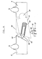
- Figure 4 illustrates in more detail, a reverse angle view of the switch as shown in Figures 3A-3C. and illustrates the components which allow the switch to be moved between open and closed positions.
- the screw 50 which is used to move the switch by turning of the screw in relation to the connector body includes a resilient spring 52.
- the switch 16 is provided at one with a pivotal point connection 54 with the contact means 6 so that electrical connection between the switch and contact means 6 is possible and, within the body of the switch there is provided a member 56 which is acted upon by a spring 58, said spring attempting to force the member outwardly from the switch face 60 as indicated to contact with the face 62 of the contact means 8.
- the spring 52 in the screw 50 is weaker than the spring 58 in the switch 16 when in the position shown in full lines.
- movement of the screw 50 onto the switch causes a gradual movement of the switch towards a closed position until an intermediate position of the same, which is indicated in broken lines 64, is reached.
- the strength of the spring 52 becomes greater than the compressed spring 58 in the switch so that the spring 52 causes the pointed portion 66 to move outwardly and exert a snap movement on the switch 16 from the intermediate position 64 to the fully closed position in contact with the contact means 8 and hence create the electrical contact between the contact means 6 and 8. It is this snap action which prevents arcing from occurring as the movement is sufficiently quick.
- the contact pressure of the switch when initially closed by the snap action is provided by the resilient member, further rotation of the screw 50 can be used to securely clamp together the switch contact faces to increase the current carrying capacity of the same and ensure that the contact is maintained.
- FIG. 5A and B there is shown an alternative embodiment of connector wherein there is provided an insert 100 in the form of a tab, which retains the switch 102 of the connector body 104 in an open position.
- the switch is biased to the closed position to make electrical connection between the contact means by a force applied to the switch to move it to the closed position.
- the switch moves automatically to the closed position to form the electrical connection between the contact means 106,108 in contact with in-line conductor cores 110,112 respectively.
- the present invention provides a connector which can be safely used to connect electrical conductors when the same are not live, when the same are live and, furthermore when the same are live and carrying a load.
Landscapes
- Details Of Connecting Devices For Male And Female Coupling (AREA)
- Multi-Conductor Connections (AREA)
Claims (15)
- Ein elektrischer Verbinder zum Anschluss eines wenigstens ersten spannungsführenden Leiters (34) an einen zweiten Leiter (36), wobei der besagte elektrische Verbinder einen Körper (4, 24) aus Isoliermaterial bestehend (4) aufweist, der ein erstes Kontaktsmittel (6) zum elektrischen Anschluss an den ersten Leiter enthält und ein mit Abstand angeordnetes Kontaktmittel (8) zum elektrischen Kontakt an den zweiten Leiter und einen Schalter (16), der aus einer offenen Stellung, in der kein elektrischer Kontakt zwischen den Leitern zustande kommt und einer geschlossenen Stellung, in der elektrischer Kontakt zwischen dem besagten ersten und zweiten Kontakt-mitteln (6, 8) hergestellt wird, um so eine elektrische Verbindung zwischen den besagten Leitern herzustellen, und dadurch gekennzeichnet ist, dass der elektrische Verbinder einen Einsatz (100) aufweist, besagter Einsatz in einer Position bereitgestellt wird, um den Schalter in einer offenen, nicht ange-schlossenen Stellung zu halten, wobei besagter Einsatz entfernbar ist, so dass der Schalter sich automatisch in eine geschlossene Kontaktstellung bewegen kann.
- Ein elektrischer Verbinder nach Anspruch 1, dadurch gekennzeichnet, dass das erste und zweite Kontaktmittel Einsätze sind, die aus stromdurch-lässigem Material bestehen, die so in dem aus Isoliermaterial bestehenden elektrischen Verbinderkörper eingesetzt und positioniert werden, dass der elektrische Verbinder zum Anschluss spannungsführender Leiter verwendet werden kann, wobei die Person, die den elektrischen Verbinder benutzt, den Isoliermaterialkörper handhabt.
- Ein elektrischer Verbinder nach Anspruch 1, dadurch gekennzeichnet, dass das erste und zweite Kontaktmittel einheitliche Körper sind und jedes Kontaktmittel an einen Leiter geklemmt ist.
- Ein elektrischer Verbinder nach Anspruch 3, dadurch gekennzeichnet, dass das Kontaktmittel ein Mittel zum Durchstoßen des Isoliermaterials an den Leitern aufweist, um eine elektrischer Verbindung mit der Ader des Leiters zu erzeugen.
- Ein elektrischer Verbinder nach Anspruch 1, dadurch gekennzeichnet, dass jedes Kontaktmittel wenigstens aus zwei Teilen besteht, wobei besagte Teile angeordnet sind, in elektrischem Kontakt mit dem Leiter zu stehen.
- Ein elektrischer Verbinder nach einem beliebigen der vorherigen An-spruch, dadurch gekennzeichnet, dass der Leiter mit dem Kontaktmittel in Kontakt steht, indem wenigstens ein Eingriffsmittel betrieben wird, um einen elektrischen Kontakt zwischen dem Leiter und Kontaktmittel herzustellen.
- Ein elektrischer Verbinder nach Anspruch 1, dadurch gekennzeichnet, dass die Schalterverbindung auf eine geschlossene Stellung vorgespannt ist.
- Ein elektrischer Verbinder nach einem beliebigen der vorherigen Ansprüche, dadurch gekennzeichnet, dass der Schalteranschluss zwischen dem ersten und zweiten Kontaktmittel ein Kniehebel ist.
- Ein elektrischer Verbinder nach Anspruch 8, dadurch gekennzeichnet, dass der Schalter steigend aus einer offenen Stellung in eine Zwischenstel-ung bewegt werden kann, worauf der Schalter die verbleibende Entfernung in eine geschlossene Kontaktstellung durch einen Schnappvorgang durchführt.
- Ein elektrischer Verbinder nach Anspruch 9, dadurch gekennzeichnet, dass der Schalter in der Zwischenstellung vor dem Schnappvorgang bewegt wird, indem eine Schraube gedreht wird, die mit dem Körper des elektrischen Verbinders verbunden ist.
- Ein elektrischer Verbinder nach Anspruch 9, dadurch gekennzeichnet, dass der Schnappvorgang durch die Bereitstellung eines federndes Gliedes, das in einem gespannten Zustand gehalten wird, erzeugt wird und welches, wenn der Schalter die Zwischenstellung erreicht, sich in Richtung einer ent-spannten Stellung bewegt und den Schalter mit einem Schnappvorgang bewegt, um den Anschluss zwischen dem ersten und zweiten Kontaktmittel herzustellen.
- Ein elektrischer Verbinder nach einem beliebigen der vorherigen An-sprüche dadurch gekennzeichnet, dass nach Bewegung der Schalterver-bindung in die geschlossene Anschlussstellung, dieselbe die in dieser Stellung gehalten wird.
- Eine Methode zur Bildung einer elektronischen Verbindung zwischen wenigstens einem ersten spannungsführenden Leiter (34) mit einem zweiten Leiter (36), besagter Leiter mit einem weiteren Leiter und/oder unabhängig zu steuernden elektrischen Komponenten verbunden ist oder Einrichtungen, die dem Anschluss nachgeordnet sind, durch den eine Last erzeugt werden kann, wenn in einem angeschalteten Zustand, wenn elektrischer Anschluss zwischen den Leitern durch den elektrischen Verbinder hergestellt wird, besagter gebildeter Leiterkörper (2, 24) aus Isoliermaterial (4) gebildet ist und wenigstens ein elektrisches Kontaktmittel (6, 8) für jeden der Leiter aufweist, die aus folgenden Schritten besteht:jeden der spannungsführenden Leiter greifen, indem Isoliermaterial die Adern derselben umgibt;jeden der Leiter in Stellung im Verbinderkörper positionieren;das Kontaktmittel (6,8) auf entsprechende Leiter (34, 36) bewegen, um elektrischen Kontakt mit denselben herzustellen, dadurch gekennzeichnet, dass die Kontaktmittel durch einen Schalter (16) elektrisch in einer offenen Stellung getrennt sind und wenn die Kontaktmittel (6, 8) in Kontakt mit den entsprechenden Leitern stehen, der Schalter in eine geschlossene Stellung bewegt wird, um die Kontaktmittel und somit die Leiter elektrisch zu verbin-den, indem ein Einsatz entfernt wird, der zu Anfang bereitgestellt wird, um den Schalter in einem offen Zustand zu halten und die Entfernung die automa-tische Bewegung in einen geschlossene Kontaktstellung verursacht.
- Eine Methode nach Anspruch 13, dadurch gekennzeichnet, dass der Schalteranschluss in eine geschlossene Stellung vorgespannt ist.
- Eine Methode nach Anspruch 13, dadurch gekennzeichnet, dass der Schalteranschluss mechanisch in eine Zwischenstellung bewegt wird, aus der der Schalteranschluss automatisch in eine geschlossene Stellung bewegt wird.
Applications Claiming Priority (4)
| Application Number | Priority Date | Filing Date | Title |
|---|---|---|---|
| GB9808544 | 1998-04-23 | ||
| GBGB9808544.2A GB9808544D0 (en) | 1998-04-23 | 1998-04-23 | Connector |
| GB9822739 | 1998-10-20 | ||
| GBGB9822739.0A GB9822739D0 (en) | 1998-10-20 | 1998-10-20 | Connector |
Publications (2)
| Publication Number | Publication Date |
|---|---|
| EP0952627A1 EP0952627A1 (de) | 1999-10-27 |
| EP0952627B1 true EP0952627B1 (de) | 2007-10-03 |
Family
ID=26313508
Family Applications (1)
| Application Number | Title | Priority Date | Filing Date |
|---|---|---|---|
| EP99303058A Expired - Lifetime EP0952627B1 (de) | 1998-04-23 | 1999-04-20 | Elektrischer Verbinder |
Country Status (3)
| Country | Link |
|---|---|
| EP (1) | EP0952627B1 (de) |
| AT (1) | ATE375018T1 (de) |
| DE (1) | DE69937212T2 (de) |
Families Citing this family (2)
| Publication number | Priority date | Publication date | Assignee | Title |
|---|---|---|---|---|
| GB0607682D0 (en) * | 2006-04-19 | 2006-05-31 | Sicame Electrical Dev Ltd | Electrical conductor connector |
| CN115911969B (zh) * | 2021-08-17 | 2026-05-05 | 西安西电高压开关有限责任公司 | 自锁型电连接结构及高压开关设备 |
Family Cites Families (4)
| Publication number | Priority date | Publication date | Assignee | Title |
|---|---|---|---|---|
| GB697065A (en) * | 1950-12-26 | 1953-09-16 | Charles Edwin Gilbert | Improvements in line cord switch |
| US3792212A (en) * | 1971-08-17 | 1974-02-12 | Eagle Electric Mfg Co Inc | Snap action electric switch |
| EP0015356B1 (de) * | 1978-10-13 | 1983-08-03 | F.LLI ZUCCHINI S.p.A. | Zweipoliger Stromabnehmer für mehrpolige abgeschirmte elektrische Leitungen |
| GB9308515D0 (en) * | 1993-04-15 | 1993-06-09 | Sicame Electrical Dev Ltd | Improvements relating to underground cable connectors |
-
1999
- 1999-04-20 EP EP99303058A patent/EP0952627B1/de not_active Expired - Lifetime
- 1999-04-20 AT AT99303058T patent/ATE375018T1/de active
- 1999-04-20 DE DE69937212T patent/DE69937212T2/de not_active Expired - Lifetime
Also Published As
| Publication number | Publication date |
|---|---|
| DE69937212D1 (de) | 2007-11-15 |
| EP0952627A1 (de) | 1999-10-27 |
| DE69937212T2 (de) | 2008-07-03 |
| ATE375018T1 (de) | 2007-10-15 |
Similar Documents
| Publication | Publication Date | Title |
|---|---|---|
| US6265680B1 (en) | Electrical circuit breaker having an insulation displacement connector assembly | |
| CA3012118C (en) | Apparatus for isolating a network protector in an electric power distribution network | |
| EP3195338B1 (de) | Stromverwaltungsvorrichtung | |
| TWI506662B (zh) | 電源線隔離裝置及其製作、使用方法 | |
| CN107004527B (zh) | 低剖面可熔性分离开关装置 | |
| US7247045B1 (en) | Modular connection assembly | |
| EP1085600B1 (de) | Anordnung eines elektrischen Anschlusses | |
| EP0952627A1 (de) | Elektrischer Verbinder | |
| US5315475A (en) | Electrician's free power cord | |
| KR100882790B1 (ko) | 지상변압기의 저압케이블 분리용 집게형 접속장치 | |
| EP1848062B1 (de) | Steckverbinder für elektrische Leiter | |
| KR100785879B1 (ko) | 지상 변압기의 저압 케이블 분리용 집게형 접속장치 | |
| US11417967B2 (en) | Electrical power connection device | |
| KR200441145Y1 (ko) | 차단기의 아크런너와 고정단자의 결합구조 | |
| US4929920A (en) | Compact circuit breaker with an electronic trip unit | |
| EP1004159B1 (de) | Verbindungsschalter | |
| KR100459215B1 (ko) | 배선용 차단기 단자와 압착단자의 접속구조 | |
| KR20030057081A (ko) | 접지스위치 | |
| EP4283651A1 (de) | Trennschalteranordnung einer schaltanlage | |
| KR200431619Y1 (ko) | 지상 변압기의 저압 케이블 분리용 집게형 접속장치 | |
| CN223427972U (zh) | 外部线路便于整理的电气开关柜 | |
| CN220066105U (zh) | 一种便于接线的负荷开关 | |
| CN113903637A (zh) | 带有双滑块组件和把手偏置元件的大电流紧凑型可熔断路开关 | |
| GB2338600A (en) | High voltage switchgear with earth switch connection | |
| CN218276081U (zh) | 一种能够快速分割负荷的配电电路及配电箱 |
Legal Events
| Date | Code | Title | Description |
|---|---|---|---|
| PUAI | Public reference made under article 153(3) epc to a published international application that has entered the european phase |
Free format text: ORIGINAL CODE: 0009012 |
|
| AK | Designated contracting states |
Kind code of ref document: A1 Designated state(s): AT BE CH CY DE DK ES FI FR GB GR IE IT LI LU MC NL PT SE |
|
| AX | Request for extension of the european patent |
Free format text: AL PAYMENT 19990505;LT PAYMENT 19990505;LV PAYMENT 19990505;MK PAYMENT 19990505;RO PAYMENT 19990505;SI PAYMENT 19990505 |
|
| 17P | Request for examination filed |
Effective date: 20000414 |
|
| AKX | Designation fees paid |
Free format text: AT BE CH CY DE DK ES FI FR GB GR IE IT LI LU MC NL PT SE |
|
| AXX | Extension fees paid |
Free format text: AL PAYMENT 19990505;LT PAYMENT 19990505;LV PAYMENT 19990505;MK PAYMENT 19990505;RO PAYMENT 19990505;SI PAYMENT 19990505 |
|
| 17Q | First examination report despatched |
Effective date: 20021218 |
|
| 17Q | First examination report despatched |
Effective date: 20050715 |
|
| GRAP | Despatch of communication of intention to grant a patent |
Free format text: ORIGINAL CODE: EPIDOSNIGR1 |
|
| GRAS | Grant fee paid |
Free format text: ORIGINAL CODE: EPIDOSNIGR3 |
|
| GRAA | (expected) grant |
Free format text: ORIGINAL CODE: 0009210 |
|
| AK | Designated contracting states |
Kind code of ref document: B1 Designated state(s): AT BE CH CY DE DK ES FI FR GB GR IE IT LI LU MC NL PT SE |
|
| AX | Request for extension of the european patent |
Extension state: AL LT LV MK RO SI |
|
| REG | Reference to a national code |
Ref country code: GB Ref legal event code: FG4D |
|
| REG | Reference to a national code |
Ref country code: CH Ref legal event code: EP |
|
| REG | Reference to a national code |
Ref country code: IE Ref legal event code: FG4D |
|
| REF | Corresponds to: |
Ref document number: 69937212 Country of ref document: DE Date of ref document: 20071115 Kind code of ref document: P |
|
| ET | Fr: translation filed | ||
| NLV1 | Nl: lapsed or annulled due to failure to fulfill the requirements of art. 29p and 29m of the patents act | ||
| REG | Reference to a national code |
Ref country code: CH Ref legal event code: PL |
|
| PG25 | Lapsed in a contracting state [announced via postgrant information from national office to epo] |
Ref country code: SE Free format text: LAPSE BECAUSE OF FAILURE TO SUBMIT A TRANSLATION OF THE DESCRIPTION OR TO PAY THE FEE WITHIN THE PRESCRIBED TIME-LIMIT Effective date: 20080103 Ref country code: NL Free format text: LAPSE BECAUSE OF FAILURE TO SUBMIT A TRANSLATION OF THE DESCRIPTION OR TO PAY THE FEE WITHIN THE PRESCRIBED TIME-LIMIT Effective date: 20071003 Ref country code: LI Free format text: LAPSE BECAUSE OF FAILURE TO SUBMIT A TRANSLATION OF THE DESCRIPTION OR TO PAY THE FEE WITHIN THE PRESCRIBED TIME-LIMIT Effective date: 20071003 Ref country code: ES Free format text: LAPSE BECAUSE OF FAILURE TO SUBMIT A TRANSLATION OF THE DESCRIPTION OR TO PAY THE FEE WITHIN THE PRESCRIBED TIME-LIMIT Effective date: 20080114 Ref country code: CH Free format text: LAPSE BECAUSE OF FAILURE TO SUBMIT A TRANSLATION OF THE DESCRIPTION OR TO PAY THE FEE WITHIN THE PRESCRIBED TIME-LIMIT Effective date: 20071003 |
|
| PG25 | Lapsed in a contracting state [announced via postgrant information from national office to epo] |
Ref country code: PT Free format text: LAPSE BECAUSE OF FAILURE TO SUBMIT A TRANSLATION OF THE DESCRIPTION OR TO PAY THE FEE WITHIN THE PRESCRIBED TIME-LIMIT Effective date: 20080303 |
|
| PG25 | Lapsed in a contracting state [announced via postgrant information from national office to epo] |
Ref country code: DK Free format text: LAPSE BECAUSE OF FAILURE TO SUBMIT A TRANSLATION OF THE DESCRIPTION OR TO PAY THE FEE WITHIN THE PRESCRIBED TIME-LIMIT Effective date: 20071003 |
|
| PLBE | No opposition filed within time limit |
Free format text: ORIGINAL CODE: 0009261 |
|
| STAA | Information on the status of an ep patent application or granted ep patent |
Free format text: STATUS: NO OPPOSITION FILED WITHIN TIME LIMIT |
|
| PG25 | Lapsed in a contracting state [announced via postgrant information from national office to epo] |
Ref country code: BE Free format text: LAPSE BECAUSE OF FAILURE TO SUBMIT A TRANSLATION OF THE DESCRIPTION OR TO PAY THE FEE WITHIN THE PRESCRIBED TIME-LIMIT Effective date: 20071003 |
|
| 26N | No opposition filed |
Effective date: 20080704 |
|
| PG25 | Lapsed in a contracting state [announced via postgrant information from national office to epo] |
Ref country code: MC Free format text: LAPSE BECAUSE OF NON-PAYMENT OF DUE FEES Effective date: 20080430 |
|
| PG25 | Lapsed in a contracting state [announced via postgrant information from national office to epo] |
Ref country code: GR Free format text: LAPSE BECAUSE OF FAILURE TO SUBMIT A TRANSLATION OF THE DESCRIPTION OR TO PAY THE FEE WITHIN THE PRESCRIBED TIME-LIMIT Effective date: 20080104 |
|
| PG25 | Lapsed in a contracting state [announced via postgrant information from national office to epo] |
Ref country code: IE Free format text: LAPSE BECAUSE OF NON-PAYMENT OF DUE FEES Effective date: 20080421 |
|
| PG25 | Lapsed in a contracting state [announced via postgrant information from national office to epo] |
Ref country code: CY Free format text: LAPSE BECAUSE OF FAILURE TO SUBMIT A TRANSLATION OF THE DESCRIPTION OR TO PAY THE FEE WITHIN THE PRESCRIBED TIME-LIMIT Effective date: 20071003 |
|
| PG25 | Lapsed in a contracting state [announced via postgrant information from national office to epo] |
Ref country code: FI Free format text: LAPSE BECAUSE OF FAILURE TO SUBMIT A TRANSLATION OF THE DESCRIPTION OR TO PAY THE FEE WITHIN THE PRESCRIBED TIME-LIMIT Effective date: 20071003 |
|
| PG25 | Lapsed in a contracting state [announced via postgrant information from national office to epo] |
Ref country code: LU Free format text: LAPSE BECAUSE OF NON-PAYMENT OF DUE FEES Effective date: 20080420 |
|
| PG25 | Lapsed in a contracting state [announced via postgrant information from national office to epo] |
Ref country code: IT Free format text: LAPSE BECAUSE OF NON-PAYMENT OF DUE FEES Effective date: 20080430 |
|
| PGFP | Annual fee paid to national office [announced via postgrant information from national office to epo] |
Ref country code: FR Payment date: 20120306 Year of fee payment: 14 |
|
| PGFP | Annual fee paid to national office [announced via postgrant information from national office to epo] |
Ref country code: DE Payment date: 20120221 Year of fee payment: 14 |
|
| REG | Reference to a national code |
Ref country code: DE Ref legal event code: R082 Ref document number: 69937212 Country of ref document: DE Representative=s name: MAI DOERR BESIER PATENTANWAELTE, DE |
|
| PGFP | Annual fee paid to national office [announced via postgrant information from national office to epo] |
Ref country code: AT Payment date: 20120221 Year of fee payment: 14 |
|
| REG | Reference to a national code |
Ref country code: AT Ref legal event code: MM01 Ref document number: 375018 Country of ref document: AT Kind code of ref document: T Effective date: 20130430 |
|
| PG25 | Lapsed in a contracting state [announced via postgrant information from national office to epo] |
Ref country code: AT Free format text: LAPSE BECAUSE OF NON-PAYMENT OF DUE FEES Effective date: 20130430 Ref country code: DE Free format text: LAPSE BECAUSE OF NON-PAYMENT OF DUE FEES Effective date: 20131101 |
|
| REG | Reference to a national code |
Ref country code: FR Ref legal event code: ST Effective date: 20131231 |
|
| REG | Reference to a national code |
Ref country code: DE Ref legal event code: R119 Ref document number: 69937212 Country of ref document: DE Effective date: 20131101 |
|
| PG25 | Lapsed in a contracting state [announced via postgrant information from national office to epo] |
Ref country code: FR Free format text: LAPSE BECAUSE OF NON-PAYMENT OF DUE FEES Effective date: 20130430 |
|
| PGFP | Annual fee paid to national office [announced via postgrant information from national office to epo] |
Ref country code: GB Payment date: 20140205 Year of fee payment: 16 |
|
| GBPC | Gb: european patent ceased through non-payment of renewal fee |
Effective date: 20150420 |
|
| PG25 | Lapsed in a contracting state [announced via postgrant information from national office to epo] |
Ref country code: GB Free format text: LAPSE BECAUSE OF NON-PAYMENT OF DUE FEES Effective date: 20150420 |