EP0952429A1 - Capteur d'angles optique - Google Patents
Capteur d'angles optique Download PDFInfo
- Publication number
- EP0952429A1 EP0952429A1 EP99107849A EP99107849A EP0952429A1 EP 0952429 A1 EP0952429 A1 EP 0952429A1 EP 99107849 A EP99107849 A EP 99107849A EP 99107849 A EP99107849 A EP 99107849A EP 0952429 A1 EP0952429 A1 EP 0952429A1
- Authority
- EP
- European Patent Office
- Prior art keywords
- code
- track
- signals
- encoder
- signal
- Prior art date
- Legal status (The legal status is an assumption and is not a legal conclusion. Google has not performed a legal analysis and makes no representation as to the accuracy of the status listed.)
- Granted
Links
- 230000003287 optical effect Effects 0.000 title description 2
- 238000011156 evaluation Methods 0.000 claims abstract description 9
- 238000000034 method Methods 0.000 claims abstract description 8
- 230000005693 optoelectronics Effects 0.000 claims abstract 6
- 238000005070 sampling Methods 0.000 claims description 8
- 238000006243 chemical reaction Methods 0.000 claims description 5
- 230000009977 dual effect Effects 0.000 claims description 3
- 238000001514 detection method Methods 0.000 claims description 2
- 230000010363 phase shift Effects 0.000 claims 1
- 238000005259 measurement Methods 0.000 abstract 2
- 238000010586 diagram Methods 0.000 description 3
- 230000005540 biological transmission Effects 0.000 description 2
- 238000011161 development Methods 0.000 description 2
- 238000004519 manufacturing process Methods 0.000 description 2
- 238000003491 array Methods 0.000 description 1
- 238000010276 construction Methods 0.000 description 1
- 230000001419 dependent effect Effects 0.000 description 1
- 238000013461 design Methods 0.000 description 1
- 238000005516 engineering process Methods 0.000 description 1
- 230000008092 positive effect Effects 0.000 description 1
- 238000012545 processing Methods 0.000 description 1
- 238000007493 shaping process Methods 0.000 description 1
Images

Classifications
-
- G—PHYSICS
- G01—MEASURING; TESTING
- G01D—MEASURING NOT SPECIALLY ADAPTED FOR A SPECIFIC VARIABLE; ARRANGEMENTS FOR MEASURING TWO OR MORE VARIABLES NOT COVERED IN A SINGLE OTHER SUBCLASS; TARIFF METERING APPARATUS; MEASURING OR TESTING NOT OTHERWISE PROVIDED FOR
- G01D5/00—Mechanical means for transferring the output of a sensing member; Means for converting the output of a sensing member to another variable where the form or nature of the sensing member does not constrain the means for converting; Transducers not specially adapted for a specific variable
- G01D5/26—Mechanical means for transferring the output of a sensing member; Means for converting the output of a sensing member to another variable where the form or nature of the sensing member does not constrain the means for converting; Transducers not specially adapted for a specific variable characterised by optical transfer means, i.e. using infrared, visible, or ultraviolet light
- G01D5/32—Mechanical means for transferring the output of a sensing member; Means for converting the output of a sensing member to another variable where the form or nature of the sensing member does not constrain the means for converting; Transducers not specially adapted for a specific variable characterised by optical transfer means, i.e. using infrared, visible, or ultraviolet light with attenuation or whole or partial obturation of beams of light
- G01D5/34—Mechanical means for transferring the output of a sensing member; Means for converting the output of a sensing member to another variable where the form or nature of the sensing member does not constrain the means for converting; Transducers not specially adapted for a specific variable characterised by optical transfer means, i.e. using infrared, visible, or ultraviolet light with attenuation or whole or partial obturation of beams of light the beams of light being detected by photocells
- G01D5/36—Forming the light into pulses
-
- G—PHYSICS
- G01—MEASURING; TESTING
- G01D—MEASURING NOT SPECIALLY ADAPTED FOR A SPECIFIC VARIABLE; ARRANGEMENTS FOR MEASURING TWO OR MORE VARIABLES NOT COVERED IN A SINGLE OTHER SUBCLASS; TARIFF METERING APPARATUS; MEASURING OR TESTING NOT OTHERWISE PROVIDED FOR
- G01D5/00—Mechanical means for transferring the output of a sensing member; Means for converting the output of a sensing member to another variable where the form or nature of the sensing member does not constrain the means for converting; Transducers not specially adapted for a specific variable
- G01D5/12—Mechanical means for transferring the output of a sensing member; Means for converting the output of a sensing member to another variable where the form or nature of the sensing member does not constrain the means for converting; Transducers not specially adapted for a specific variable using electric or magnetic means
- G01D5/244—Mechanical means for transferring the output of a sensing member; Means for converting the output of a sensing member to another variable where the form or nature of the sensing member does not constrain the means for converting; Transducers not specially adapted for a specific variable using electric or magnetic means influencing characteristics of pulses or pulse trains; generating pulses or pulse trains
- G01D5/245—Mechanical means for transferring the output of a sensing member; Means for converting the output of a sensing member to another variable where the form or nature of the sensing member does not constrain the means for converting; Transducers not specially adapted for a specific variable using electric or magnetic means influencing characteristics of pulses or pulse trains; generating pulses or pulse trains using a variable number of pulses in a train
- G01D5/2454—Encoders incorporating incremental and absolute signals
- G01D5/2455—Encoders incorporating incremental and absolute signals with incremental and absolute tracks on the same encoder
-
- G—PHYSICS
- G01—MEASURING; TESTING
- G01D—MEASURING NOT SPECIALLY ADAPTED FOR A SPECIFIC VARIABLE; ARRANGEMENTS FOR MEASURING TWO OR MORE VARIABLES NOT COVERED IN A SINGLE OTHER SUBCLASS; TARIFF METERING APPARATUS; MEASURING OR TESTING NOT OTHERWISE PROVIDED FOR
- G01D5/00—Mechanical means for transferring the output of a sensing member; Means for converting the output of a sensing member to another variable where the form or nature of the sensing member does not constrain the means for converting; Transducers not specially adapted for a specific variable
- G01D5/12—Mechanical means for transferring the output of a sensing member; Means for converting the output of a sensing member to another variable where the form or nature of the sensing member does not constrain the means for converting; Transducers not specially adapted for a specific variable using electric or magnetic means
- G01D5/244—Mechanical means for transferring the output of a sensing member; Means for converting the output of a sensing member to another variable where the form or nature of the sensing member does not constrain the means for converting; Transducers not specially adapted for a specific variable using electric or magnetic means influencing characteristics of pulses or pulse trains; generating pulses or pulse trains
- G01D5/249—Mechanical means for transferring the output of a sensing member; Means for converting the output of a sensing member to another variable where the form or nature of the sensing member does not constrain the means for converting; Transducers not specially adapted for a specific variable using electric or magnetic means influencing characteristics of pulses or pulse trains; generating pulses or pulse trains using pulse code
- G01D5/2492—Pulse stream
Definitions
- the invention is based on a method according to the preamble of independent patent claim 1 and a sensor unit for sensor systems according to the preamble of independent patent claim 5.
- a corresponding coding is arranged on a turntable, which e.g. works in transmitted light or reflection mode, and the corresponding sensor for detecting the coding is arranged opposite the turntable.
- a disadvantage of the known optical decoding systems is that a corresponding coding track is required for each signal on the coding carrier designed as a turntable, which is associated with a high space requirement. For example, one track must be executed per bit of the digital output signal, which means that (e.g. with 12 bits) a disk with 12 tracks is necessary to detect the coding.
- the invention is therefore based on the object of developing a sensor unit of the type mentioned in such a way that it achieves at least the same size, or even better, resolution than that of the known systems with a significantly smaller space requirement, and in addition to the given technical teaching also lower production costs attack.
- the sensor unit therefore consists of an incremental part that provides analog or digital output signals with high resolution (e.g. 2048 periods per revolution).
- the scanning diodes for the signals A, A ', B and B' are thus interleaved on the same radius, so that the radial space requirement is minimized. If this arrangement of the scanning diodes is arranged several times on the circumference, the addition of the individual signals to a sum signal results in a larger signal level, which ensures a higher signal-to-noise ratio.
- a difference is formed between the non-inverting and the inverting signals (A, A 'and B, B').
- a line driver follows which delivers differential signals at the output.
- the absolute information is therefore obtained by scanning a special serial code.
- the scanning diodes are all on the same radius, so that the radial space requirement is minimized here. Differential scanning is used here.
- the special absolute code is converted into a conventional dual code (e.g. binary code or gray code) via a code converter, and is available in parallel, and is available after a parallel / serial conversion on a serial interface e.g. SSI available.
- a zero signal detector is used, which compares the internal code with a stored bit pattern and, if the two match, outputs a signal which corresponds to the zero signal in the standard incremental encoder.
- a sine signal is generated via a further code converter and a subsequent digital / analog conversion (DAU), which is output as a differential signal via a power driver.
- DAU digital / analog conversion
- the same is done for the cosine signal with a further code converter.
- a sine / cosine signal pair with a few periods per revolution is available here. From this, the absolute position value can be determined on the user side using the arctangent function.
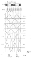
- FIG. 1 starting from number 1, a section of a code track is shown, which is evenly distributed on a concentric circle of a turntable.
- the reference numeral 10 schematically shows a photodiode track, which consists of a single-line photodiode array.
- the photo diodes in the photo array are arranged in such a way that they can detect the code track, which is evenly distributed on the turntable on a concentric circle.
- the information from the code track can be obtained in the transmitted light or in the reflection process.
- photo arrays can be used at appropriate intervals to detect the Coding be arranged.
- the signals of the corresponding photodiodes are interconnected to enable a more precise evaluation.
- Figures 1a to 1f show the corresponding signals that result from the rotary movement of the turntable.
- Figure 1a shows a sum signal of all interconnected photodiodes A, with the resulting relatively high amplitude, the peak value of which is well above the peak value of an individual photodiode, so that a relatively interference-free sum signal is achieved.
- the sum signal of the photodiodes B is shown here, which is achieved by interconnecting all the photodiodes B.
- Figures 1c and 1d show that the inverted signals of the photodiodes A and B be added up so that overall relatively high-level signal outputs are generated.
- FIGS. 1f and 1g show that by subtracting the signal levels a and a and the signal level b and b the DC components of these sum signals are eliminated, the two signal levels being shifted by 90 ° to one another.
- a period 19 is shown with reference to FIG. 1, which occurs a total of 2,048 times on the first track in the exemplary embodiment shown when the turntable is rotated through 360 °.
- the absolute information about the rotational position is obtained by scanning a special, serial code.
- the invention provides that in addition to the incremental scanning on the first track of the encoder disk, a special serial code is generated on a further track on a concentric circle. This serial code is used by the Detected photodiode track 11, which is arranged so that it can detect the additional code track.
- This photodiode track contains e.g. 11 photodiodes that generate an 11-bit code.
- a total of 11 photodiodes with the reference numerals 13-16 are thus arranged on the photodiode track 11, only 4, the two first and the last two of the entire track, being shown for the sake of simplicity.
- an additional track of the absolute value sampling (namely the photodiode track 12) is arranged, in which an inverted absolute value sampling is carried out, so that the positive and negative values of the two photodiode tracks 11, 12 relative to one another can be added, and thereby the sliding component is eliminated.
- the absolute value sampling in the form of an 11-bit word.
- more or fewer photodiodes of the photodiode track 11 or 12 can also be interconnected in order to form a code word that is more or less bit wide produce.
- the absolute information can also be arranged distributed over several code tracks.
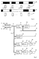
- FIG. 3 shows a block diagram for the addition of the incremental signals already illustrated and explained with reference to FIGS. 1a to 1f, on the basis of which it can be seen that the signal A with the signal A are present at the positive and negative input of an adder, which forms a difference signal from this, which is fed to a power driver.
- this power driver For power transmission, this power driver generates differential signals of 2,048 times the previously described sine curve according to FIG. 1f.
- the sine portion of the curve is evaluated in the representation with the references A and A ', and the cosine portion of the curve in the representation with the references B and B'.
- the processing of the absolute value sample is shown in FIG. 5.
- the absolute value signal of the photodiode track 11 is applied to the positive input of the adder, and the photodiode signal of the photodiode track 12 is applied to the negative input of the adder.
- the adder processes the two input values in such a way that a signal is produced which is freed from portions which have the same amount.
- This 11-bit wide code word is now fed to the code converter 37, which uses a conventional dual code, e.g. generated a binary code or a graycoce from it.
- the generated signal is available in parallel at the output 40 or can be passed through a parallel / serial converter 38, so that a serial signal is output at its output 20.
- a zero signal detector 24 is arranged at the output 21 of the adder 22 via a further branch 23.
- the zero signal detector 24 compares the parallel code present at the input in the branch 23 with a pattern stored therein, and if a match is found, a zero signal is generated at the output 41.
- This provides a reference for a full revolution of the encoder if it was rotated, for example, by a full revolution of 360 ° generates a zero signal for each revolution at output 41.
- This zero signal can also be used, for example, to form a start signal for a new program sequence in a machine tool controlled thereby.
- the digital word generated by the adder 22 and applied in parallel at the output 21 is simultaneously fed to a code converter 25 via the branch 39.
- This code converter generates a digital code sequence.
- the code converter 25 converts the code present in such a way that a sinusoidal signal is produced at the output 26 of the digital / analog converter 27 and is output on the line 29 via a power driver 28.
- the code converter 31 converts the digital word present in the branch 30 in such a way that a cosine signal is generated in the downstream digital-to-analog converter 32 and is supplied to the output 34 via the power driver 33.
- a total of 7 outputs are now available, with outputs 35, 36 containing the respective incremental signal, while the absolute, serial signal is present at output 20, absolute, parallel signal at output 40 and the zero signal at output 41.
- a sine signal or a cosine signal is generated at the outputs 29, 34 per revolution of the coded turntable.
- the code converters 25 and 31 can be programmed so that the signal shaping kx sine respectively.
- kx cosine can have, this means that it is also possible to generate two, three or even more sine or cosine functions per full revolution.
- the universal resolution of the code conversion enables software to adapt the commutation signals to different motors.
- the absolute position value is also available as a digital value, as was explained using the outputs 20 and 40.
- the standard interfaces therefore require the signals from outputs 35, 36, 29, 34 and 41, while non-standard interfaces can then additionally work with the signals from outputs 20 and 40, for example.
- the advantage of this measure is that, for example, the absolute position value is already available at signal output 20, which - with the standard interfaces - must first be calculated from the output signals of outputs 35, 36, 29, 34.
- the code conversion according to FIG. 5 is therefore important, in which a standard code word is generated from the parallel code word with the code converter 37.
- the invention thus has the advantage that the encoder shown here can be used to control both standard interfaces and to generate novel signal combinations which can be further processed in a simple manner.
Applications Claiming Priority (2)
| Application Number | Priority Date | Filing Date | Title |
|---|---|---|---|
| DE19818654 | 1998-04-25 | ||
| DE19818654A DE19818654A1 (de) | 1998-04-25 | 1998-04-25 | Sensoreinheit für Gebersysteme |
Publications (2)
| Publication Number | Publication Date |
|---|---|
| EP0952429A1 true EP0952429A1 (fr) | 1999-10-27 |
| EP0952429B1 EP0952429B1 (fr) | 2005-03-02 |
Family
ID=7865857
Family Applications (1)
| Application Number | Title | Priority Date | Filing Date |
|---|---|---|---|
| EP99107849A Expired - Lifetime EP0952429B1 (fr) | 1998-04-25 | 1999-04-21 | Capteur d'angles optique |
Country Status (2)
| Country | Link |
|---|---|
| EP (1) | EP0952429B1 (fr) |
| DE (2) | DE19818654A1 (fr) |
Cited By (4)
| Publication number | Priority date | Publication date | Assignee | Title |
|---|---|---|---|---|
| EP1114982A1 (fr) * | 2000-01-06 | 2001-07-11 | Contelec AG | Capteur d'angles |
| NL1019828C2 (nl) * | 2002-01-24 | 2003-07-25 | Skf Ab | Rotatiesnelheidsensor. |
| EP1466142A2 (fr) | 2002-01-11 | 2004-10-13 | RLS Merilna Tehnika D.O.O. | Codeur comportant des marques de reference |
| CN101984328A (zh) * | 2010-08-20 | 2011-03-09 | 西南交通大学 | 一种单码道光电编码器 |
Families Citing this family (1)
| Publication number | Priority date | Publication date | Assignee | Title |
|---|---|---|---|---|
| DE10301848B4 (de) * | 2003-01-09 | 2014-10-09 | Anton Rodi | Messeinrichtung zur Erfassung von Größen, insbesondere von Winkeln oder Wegstrecken |
Citations (5)
| Publication number | Priority date | Publication date | Assignee | Title |
|---|---|---|---|---|
| EP0102241A2 (fr) * | 1982-08-31 | 1984-03-07 | Sharp Kabushiki Kaisha | Codeur optique de rotation |
| WO1986000478A1 (fr) * | 1984-06-22 | 1986-01-16 | Bei Electronics, Inc. | Codeur de codes a enchainement |
| EP0575663A1 (fr) * | 1992-05-23 | 1993-12-29 | VDO Adolf Schindling AG | Capteur pour produire les signaux électriques, indiquant la position d'un objet |
| US5444613A (en) * | 1990-07-30 | 1995-08-22 | Teac Corporation | Device for generating a signal representative of the position of an angularly or linearly moveable member |
| EP0825420A1 (fr) * | 1996-08-21 | 1998-02-25 | General Motors Corporation | Codeur d'angle absolut |
Family Cites Families (6)
| Publication number | Priority date | Publication date | Assignee | Title |
|---|---|---|---|---|
| JPH03285114A (ja) * | 1990-04-02 | 1991-12-16 | Nikon Corp | 1トラック型アブソリュート・エンコーダ用符号板 |
| JPH03287013A (ja) * | 1990-04-03 | 1991-12-17 | Nikon Corp | 符号板、および該符号板を用いたアブソリュートエンコーダ |
| JP2691942B2 (ja) * | 1990-04-16 | 1997-12-17 | 株式会社ニコン | ロータリー式アブソリュートエンコーダ |
| US5279044A (en) * | 1991-03-12 | 1994-01-18 | U.S. Philips Corporation | Measuring device for determining an absolute position of a movable element and scale graduation element suitable for use in such a measuring device |
| DE4436784B4 (de) * | 1993-10-26 | 2005-08-18 | Carl Zeiss | Absolutes Positionsmeßsystem |
| DE19518664C2 (de) * | 1995-05-20 | 2003-02-13 | Christian Rathjen | Verfahren zur Bestimmung der Position zweier zueinander bewegbarer Körper |
-
1998
- 1998-04-25 DE DE19818654A patent/DE19818654A1/de not_active Ceased
-
1999
- 1999-04-21 DE DE59911673T patent/DE59911673D1/de not_active Expired - Lifetime
- 1999-04-21 EP EP99107849A patent/EP0952429B1/fr not_active Expired - Lifetime
Patent Citations (5)
| Publication number | Priority date | Publication date | Assignee | Title |
|---|---|---|---|---|
| EP0102241A2 (fr) * | 1982-08-31 | 1984-03-07 | Sharp Kabushiki Kaisha | Codeur optique de rotation |
| WO1986000478A1 (fr) * | 1984-06-22 | 1986-01-16 | Bei Electronics, Inc. | Codeur de codes a enchainement |
| US5444613A (en) * | 1990-07-30 | 1995-08-22 | Teac Corporation | Device for generating a signal representative of the position of an angularly or linearly moveable member |
| EP0575663A1 (fr) * | 1992-05-23 | 1993-12-29 | VDO Adolf Schindling AG | Capteur pour produire les signaux électriques, indiquant la position d'un objet |
| EP0825420A1 (fr) * | 1996-08-21 | 1998-02-25 | General Motors Corporation | Codeur d'angle absolut |
Non-Patent Citations (1)
| Title |
|---|
| DURANA M ET AL: "NOVEL TYPE SUBMICROMETRE RESOLUTION PSEUDORANDOM POSITION OPTICAL ENCODER", ELECTRONICS LETTERS, vol. 29, no. 20, 30 September 1993 (1993-09-30), pages 1792 - 1794, XP000400438, ISSN: 0013-5194 * |
Cited By (7)
| Publication number | Priority date | Publication date | Assignee | Title |
|---|---|---|---|---|
| EP1114982A1 (fr) * | 2000-01-06 | 2001-07-11 | Contelec AG | Capteur d'angles |
| EP1466142A2 (fr) | 2002-01-11 | 2004-10-13 | RLS Merilna Tehnika D.O.O. | Codeur comportant des marques de reference |
| NL1019828C2 (nl) * | 2002-01-24 | 2003-07-25 | Skf Ab | Rotatiesnelheidsensor. |
| WO2003062834A1 (fr) * | 2002-01-24 | 2003-07-31 | Ab Skf | Capteur de vitesse de rotation |
| US7183760B2 (en) | 2002-01-24 | 2007-02-27 | Ab Skf | Position pickup for rotational speed sensor |
| CN101984328A (zh) * | 2010-08-20 | 2011-03-09 | 西南交通大学 | 一种单码道光电编码器 |
| CN101984328B (zh) * | 2010-08-20 | 2012-03-21 | 西南交通大学 | 一种单码道光电编码器 |
Also Published As
| Publication number | Publication date |
|---|---|
| DE19818654A1 (de) | 1999-11-04 |
| EP0952429B1 (fr) | 2005-03-02 |
| DE59911673D1 (de) | 2005-04-07 |
Similar Documents
| Publication | Publication Date | Title |
|---|---|---|
| EP0171612B1 (fr) | Appareil de mesure de la position | |
| AT404300B (de) | Drehgeber | |
| EP1315954B1 (fr) | Procede pour determiner une difference angulaire a partir de signaux de mise en phase | |
| DE4123722B4 (de) | Absolutkodierer | |
| EP1468254B1 (fr) | Dispositif de mesure de position | |
| DE3913983A1 (de) | Vorrichtung zum nachweis von verschiebungen | |
| DE3342940C2 (fr) | ||
| DE2342793A1 (de) | Digitaler magnetkompass | |
| EP1180665A2 (fr) | Dispositif capteur d'angles de braquage pour véhicules | |
| EP1255965A1 (fr) | Disque code pour une unite optoelectronique servant a mesurer un deplacement ou un angle | |
| EP1457762B1 (fr) | Dispositif pour mesurer la position, le déplacement ou l'angle de rotation d'un objet | |
| EP0952429A1 (fr) | Capteur d'angles optique | |
| EP1770375B1 (fr) | Dispositif de mesure de position comprenant deux echelles de mesure dont les pistes codées se chevauchent mutuellement | |
| DE3510651A1 (de) | Inkrementaler weggeber | |
| DE3928027C2 (de) | Absolutkodierer | |
| EP1074819B1 (fr) | Capteur d'angle de braquage | |
| DE4115244A1 (de) | Winkelsensor zur bestimmung der drehlage einer welle | |
| WO2005008182A1 (fr) | Dispositif de mesure de position permettant la determination de positions angulaires ou de longueurs | |
| EP0699896A2 (fr) | Moteur pas-à-pas avec capteur de position | |
| EP1770372A2 (fr) | Dispositif de mesure de position | |
| EP0575663B1 (fr) | Capteur pour produire les signaux électriques, indiquant la position d'une soupape de contrÔle | |
| EP0714171A2 (fr) | Dispositif et procédé pour la détermination de la position d'un corps | |
| DE4217168A1 (de) | Sensor zur Erzeugung von elektrischen Signalen, welche die Stellung eines Objekts wiedergeben | |
| DE10056448B4 (de) | Absolutes Längenmeßsystem | |
| DE4120343C2 (fr) |
Legal Events
| Date | Code | Title | Description |
|---|---|---|---|
| PUAI | Public reference made under article 153(3) epc to a published international application that has entered the european phase |
Free format text: ORIGINAL CODE: 0009012 |
|
| AK | Designated contracting states |
Kind code of ref document: A1 Designated state(s): CH DE FR IT LI |
|
| AX | Request for extension of the european patent |
Free format text: AL;LT;LV;MK;RO;SI |
|
| 17P | Request for examination filed |
Effective date: 20000422 |
|
| AKX | Designation fees paid |
Free format text: CH DE FR IT LI |
|
| 17Q | First examination report despatched |
Effective date: 20030923 |
|
| GRAP | Despatch of communication of intention to grant a patent |
Free format text: ORIGINAL CODE: EPIDOSNIGR1 |
|
| GRAS | Grant fee paid |
Free format text: ORIGINAL CODE: EPIDOSNIGR3 |
|
| GRAA | (expected) grant |
Free format text: ORIGINAL CODE: 0009210 |
|
| AK | Designated contracting states |
Kind code of ref document: B1 Designated state(s): CH DE FR IT LI |
|
| PG25 | Lapsed in a contracting state [announced via postgrant information from national office to epo] |
Ref country code: IT Free format text: LAPSE BECAUSE OF FAILURE TO SUBMIT A TRANSLATION OF THE DESCRIPTION OR TO PAY THE FEE WITHIN THE PRESCRIBED TIME-LIMIT;WARNING: LAPSES OF ITALIAN PATENTS WITH EFFECTIVE DATE BEFORE 2007 MAY HAVE OCCURRED AT ANY TIME BEFORE 2007. THE CORRECT EFFECTIVE DATE MAY BE DIFFERENT FROM THE ONE RECORDED. Effective date: 20050302 Ref country code: FR Free format text: LAPSE BECAUSE OF NON-PAYMENT OF DUE FEES Effective date: 20050302 |
|
| REG | Reference to a national code |
Ref country code: CH Ref legal event code: EP |
|
| REF | Corresponds to: |
Ref document number: 59911673 Country of ref document: DE Date of ref document: 20050407 Kind code of ref document: P |
|
| PG25 | Lapsed in a contracting state [announced via postgrant information from national office to epo] |
Ref country code: LI Free format text: LAPSE BECAUSE OF NON-PAYMENT OF DUE FEES Effective date: 20050430 Ref country code: CH Free format text: LAPSE BECAUSE OF NON-PAYMENT OF DUE FEES Effective date: 20050430 |
|
| REG | Reference to a national code |
Ref country code: CH Ref legal event code: PL |
|
| PLBE | No opposition filed within time limit |
Free format text: ORIGINAL CODE: 0009261 |
|
| STAA | Information on the status of an ep patent application or granted ep patent |
Free format text: STATUS: NO OPPOSITION FILED WITHIN TIME LIMIT |
|
| 26N | No opposition filed |
Effective date: 20051205 |
|
| EN | Fr: translation not filed | ||
| PGFP | Annual fee paid to national office [announced via postgrant information from national office to epo] |
Ref country code: DE Payment date: 20171023 Year of fee payment: 19 |
|
| REG | Reference to a national code |
Ref country code: DE Ref legal event code: R119 Ref document number: 59911673 Country of ref document: DE |
|
| PG25 | Lapsed in a contracting state [announced via postgrant information from national office to epo] |
Ref country code: DE Free format text: LAPSE BECAUSE OF NON-PAYMENT OF DUE FEES Effective date: 20181101 |