EP0952429A1 - Optical angle sensor - Google Patents
Optical angle sensor Download PDFInfo
- Publication number
- EP0952429A1 EP0952429A1 EP99107849A EP99107849A EP0952429A1 EP 0952429 A1 EP0952429 A1 EP 0952429A1 EP 99107849 A EP99107849 A EP 99107849A EP 99107849 A EP99107849 A EP 99107849A EP 0952429 A1 EP0952429 A1 EP 0952429A1
- Authority
- EP
- European Patent Office
- Prior art keywords
- code
- track
- signals
- encoder
- signal
- Prior art date
- Legal status (The legal status is an assumption and is not a legal conclusion. Google has not performed a legal analysis and makes no representation as to the accuracy of the status listed.)
- Granted
Links
- 230000003287 optical effect Effects 0.000 title 1
- 238000011156 evaluation Methods 0.000 claims abstract 6
- 230000005693 optoelectronics Effects 0.000 claims abstract 6
- 238000000034 method Methods 0.000 claims abstract 4
- 238000005070 sampling Methods 0.000 claims 3
- 238000006243 chemical reaction Methods 0.000 claims 1
- 238000001514 detection method Methods 0.000 claims 1
- 230000009977 dual effect Effects 0.000 claims 1
- 230000010363 phase shift Effects 0.000 claims 1
- 238000005259 measurement Methods 0.000 abstract 2
Images

Classifications
-
- G—PHYSICS
- G01—MEASURING; TESTING
- G01D—MEASURING NOT SPECIALLY ADAPTED FOR A SPECIFIC VARIABLE; ARRANGEMENTS FOR MEASURING TWO OR MORE VARIABLES NOT COVERED IN A SINGLE OTHER SUBCLASS; TARIFF METERING APPARATUS; MEASURING OR TESTING NOT OTHERWISE PROVIDED FOR
- G01D5/00—Mechanical means for transferring the output of a sensing member; Means for converting the output of a sensing member to another variable where the form or nature of the sensing member does not constrain the means for converting; Transducers not specially adapted for a specific variable
- G01D5/26—Mechanical means for transferring the output of a sensing member; Means for converting the output of a sensing member to another variable where the form or nature of the sensing member does not constrain the means for converting; Transducers not specially adapted for a specific variable characterised by optical transfer means, i.e. using infrared, visible, or ultraviolet light
- G01D5/32—Mechanical means for transferring the output of a sensing member; Means for converting the output of a sensing member to another variable where the form or nature of the sensing member does not constrain the means for converting; Transducers not specially adapted for a specific variable characterised by optical transfer means, i.e. using infrared, visible, or ultraviolet light with attenuation or whole or partial obturation of beams of light
- G01D5/34—Mechanical means for transferring the output of a sensing member; Means for converting the output of a sensing member to another variable where the form or nature of the sensing member does not constrain the means for converting; Transducers not specially adapted for a specific variable characterised by optical transfer means, i.e. using infrared, visible, or ultraviolet light with attenuation or whole or partial obturation of beams of light the beams of light being detected by photocells
- G01D5/36—Forming the light into pulses
-
- G—PHYSICS
- G01—MEASURING; TESTING
- G01D—MEASURING NOT SPECIALLY ADAPTED FOR A SPECIFIC VARIABLE; ARRANGEMENTS FOR MEASURING TWO OR MORE VARIABLES NOT COVERED IN A SINGLE OTHER SUBCLASS; TARIFF METERING APPARATUS; MEASURING OR TESTING NOT OTHERWISE PROVIDED FOR
- G01D5/00—Mechanical means for transferring the output of a sensing member; Means for converting the output of a sensing member to another variable where the form or nature of the sensing member does not constrain the means for converting; Transducers not specially adapted for a specific variable
- G01D5/12—Mechanical means for transferring the output of a sensing member; Means for converting the output of a sensing member to another variable where the form or nature of the sensing member does not constrain the means for converting; Transducers not specially adapted for a specific variable using electric or magnetic means
- G01D5/244—Mechanical means for transferring the output of a sensing member; Means for converting the output of a sensing member to another variable where the form or nature of the sensing member does not constrain the means for converting; Transducers not specially adapted for a specific variable using electric or magnetic means influencing characteristics of pulses or pulse trains; generating pulses or pulse trains
- G01D5/245—Mechanical means for transferring the output of a sensing member; Means for converting the output of a sensing member to another variable where the form or nature of the sensing member does not constrain the means for converting; Transducers not specially adapted for a specific variable using electric or magnetic means influencing characteristics of pulses or pulse trains; generating pulses or pulse trains using a variable number of pulses in a train
- G01D5/2454—Encoders incorporating incremental and absolute signals
- G01D5/2455—Encoders incorporating incremental and absolute signals with incremental and absolute tracks on the same encoder
-
- G—PHYSICS
- G01—MEASURING; TESTING
- G01D—MEASURING NOT SPECIALLY ADAPTED FOR A SPECIFIC VARIABLE; ARRANGEMENTS FOR MEASURING TWO OR MORE VARIABLES NOT COVERED IN A SINGLE OTHER SUBCLASS; TARIFF METERING APPARATUS; MEASURING OR TESTING NOT OTHERWISE PROVIDED FOR
- G01D5/00—Mechanical means for transferring the output of a sensing member; Means for converting the output of a sensing member to another variable where the form or nature of the sensing member does not constrain the means for converting; Transducers not specially adapted for a specific variable
- G01D5/12—Mechanical means for transferring the output of a sensing member; Means for converting the output of a sensing member to another variable where the form or nature of the sensing member does not constrain the means for converting; Transducers not specially adapted for a specific variable using electric or magnetic means
- G01D5/244—Mechanical means for transferring the output of a sensing member; Means for converting the output of a sensing member to another variable where the form or nature of the sensing member does not constrain the means for converting; Transducers not specially adapted for a specific variable using electric or magnetic means influencing characteristics of pulses or pulse trains; generating pulses or pulse trains
- G01D5/249—Mechanical means for transferring the output of a sensing member; Means for converting the output of a sensing member to another variable where the form or nature of the sensing member does not constrain the means for converting; Transducers not specially adapted for a specific variable using electric or magnetic means influencing characteristics of pulses or pulse trains; generating pulses or pulse trains using pulse code
- G01D5/2492—Pulse stream
Definitions
- the invention is based on a method according to the preamble of independent patent claim 1 and a sensor unit for sensor systems according to the preamble of independent patent claim 5.
- a corresponding coding is arranged on a turntable, which e.g. works in transmitted light or reflection mode, and the corresponding sensor for detecting the coding is arranged opposite the turntable.
- a disadvantage of the known optical decoding systems is that a corresponding coding track is required for each signal on the coding carrier designed as a turntable, which is associated with a high space requirement. For example, one track must be executed per bit of the digital output signal, which means that (e.g. with 12 bits) a disk with 12 tracks is necessary to detect the coding.
- the invention is therefore based on the object of developing a sensor unit of the type mentioned in such a way that it achieves at least the same size, or even better, resolution than that of the known systems with a significantly smaller space requirement, and in addition to the given technical teaching also lower production costs attack.
- the sensor unit therefore consists of an incremental part that provides analog or digital output signals with high resolution (e.g. 2048 periods per revolution).
- the scanning diodes for the signals A, A ', B and B' are thus interleaved on the same radius, so that the radial space requirement is minimized. If this arrangement of the scanning diodes is arranged several times on the circumference, the addition of the individual signals to a sum signal results in a larger signal level, which ensures a higher signal-to-noise ratio.
- a difference is formed between the non-inverting and the inverting signals (A, A 'and B, B').
- a line driver follows which delivers differential signals at the output.
- the absolute information is therefore obtained by scanning a special serial code.
- the scanning diodes are all on the same radius, so that the radial space requirement is minimized here. Differential scanning is used here.
- the special absolute code is converted into a conventional dual code (e.g. binary code or gray code) via a code converter, and is available in parallel, and is available after a parallel / serial conversion on a serial interface e.g. SSI available.
- a zero signal detector is used, which compares the internal code with a stored bit pattern and, if the two match, outputs a signal which corresponds to the zero signal in the standard incremental encoder.
- a sine signal is generated via a further code converter and a subsequent digital / analog conversion (DAU), which is output as a differential signal via a power driver.
- DAU digital / analog conversion
- the same is done for the cosine signal with a further code converter.
- a sine / cosine signal pair with a few periods per revolution is available here. From this, the absolute position value can be determined on the user side using the arctangent function.
- FIG. 1 starting from number 1, a section of a code track is shown, which is evenly distributed on a concentric circle of a turntable.
- the reference numeral 10 schematically shows a photodiode track, which consists of a single-line photodiode array.
- the photo diodes in the photo array are arranged in such a way that they can detect the code track, which is evenly distributed on the turntable on a concentric circle.
- the information from the code track can be obtained in the transmitted light or in the reflection process.
- photo arrays can be used at appropriate intervals to detect the Coding be arranged.
- the signals of the corresponding photodiodes are interconnected to enable a more precise evaluation.
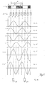
- Figures 1a to 1f show the corresponding signals that result from the rotary movement of the turntable.
- Figure 1a shows a sum signal of all interconnected photodiodes A, with the resulting relatively high amplitude, the peak value of which is well above the peak value of an individual photodiode, so that a relatively interference-free sum signal is achieved.
- the sum signal of the photodiodes B is shown here, which is achieved by interconnecting all the photodiodes B.
- Figures 1c and 1d show that the inverted signals of the photodiodes A and B be added up so that overall relatively high-level signal outputs are generated.
- FIGS. 1f and 1g show that by subtracting the signal levels a and a and the signal level b and b the DC components of these sum signals are eliminated, the two signal levels being shifted by 90 ° to one another.
- a period 19 is shown with reference to FIG. 1, which occurs a total of 2,048 times on the first track in the exemplary embodiment shown when the turntable is rotated through 360 °.
- the absolute information about the rotational position is obtained by scanning a special, serial code.
- the invention provides that in addition to the incremental scanning on the first track of the encoder disk, a special serial code is generated on a further track on a concentric circle. This serial code is used by the Detected photodiode track 11, which is arranged so that it can detect the additional code track.
- This photodiode track contains e.g. 11 photodiodes that generate an 11-bit code.
- a total of 11 photodiodes with the reference numerals 13-16 are thus arranged on the photodiode track 11, only 4, the two first and the last two of the entire track, being shown for the sake of simplicity.
- an additional track of the absolute value sampling (namely the photodiode track 12) is arranged, in which an inverted absolute value sampling is carried out, so that the positive and negative values of the two photodiode tracks 11, 12 relative to one another can be added, and thereby the sliding component is eliminated.
- the absolute value sampling in the form of an 11-bit word.
- more or fewer photodiodes of the photodiode track 11 or 12 can also be interconnected in order to form a code word that is more or less bit wide produce.
- the absolute information can also be arranged distributed over several code tracks.
- FIG. 3 shows a block diagram for the addition of the incremental signals already illustrated and explained with reference to FIGS. 1a to 1f, on the basis of which it can be seen that the signal A with the signal A are present at the positive and negative input of an adder, which forms a difference signal from this, which is fed to a power driver.
- this power driver For power transmission, this power driver generates differential signals of 2,048 times the previously described sine curve according to FIG. 1f.
- the sine portion of the curve is evaluated in the representation with the references A and A ', and the cosine portion of the curve in the representation with the references B and B'.
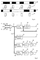
- the processing of the absolute value sample is shown in FIG. 5.
- the absolute value signal of the photodiode track 11 is applied to the positive input of the adder, and the photodiode signal of the photodiode track 12 is applied to the negative input of the adder.
- the adder processes the two input values in such a way that a signal is produced which is freed from portions which have the same amount.
- This 11-bit wide code word is now fed to the code converter 37, which uses a conventional dual code, e.g. generated a binary code or a graycoce from it.
- the generated signal is available in parallel at the output 40 or can be passed through a parallel / serial converter 38, so that a serial signal is output at its output 20.
- a zero signal detector 24 is arranged at the output 21 of the adder 22 via a further branch 23.
- the zero signal detector 24 compares the parallel code present at the input in the branch 23 with a pattern stored therein, and if a match is found, a zero signal is generated at the output 41.
- This provides a reference for a full revolution of the encoder if it was rotated, for example, by a full revolution of 360 ° generates a zero signal for each revolution at output 41.
- This zero signal can also be used, for example, to form a start signal for a new program sequence in a machine tool controlled thereby.
- the digital word generated by the adder 22 and applied in parallel at the output 21 is simultaneously fed to a code converter 25 via the branch 39.
- This code converter generates a digital code sequence.
- the code converter 25 converts the code present in such a way that a sinusoidal signal is produced at the output 26 of the digital / analog converter 27 and is output on the line 29 via a power driver 28.
- the code converter 31 converts the digital word present in the branch 30 in such a way that a cosine signal is generated in the downstream digital-to-analog converter 32 and is supplied to the output 34 via the power driver 33.
- a total of 7 outputs are now available, with outputs 35, 36 containing the respective incremental signal, while the absolute, serial signal is present at output 20, absolute, parallel signal at output 40 and the zero signal at output 41.
- a sine signal or a cosine signal is generated at the outputs 29, 34 per revolution of the coded turntable.
- the code converters 25 and 31 can be programmed so that the signal shaping kx sine respectively.
- kx cosine can have, this means that it is also possible to generate two, three or even more sine or cosine functions per full revolution.
- the universal resolution of the code conversion enables software to adapt the commutation signals to different motors.
- the absolute position value is also available as a digital value, as was explained using the outputs 20 and 40.
- the standard interfaces therefore require the signals from outputs 35, 36, 29, 34 and 41, while non-standard interfaces can then additionally work with the signals from outputs 20 and 40, for example.
- the advantage of this measure is that, for example, the absolute position value is already available at signal output 20, which - with the standard interfaces - must first be calculated from the output signals of outputs 35, 36, 29, 34.
- the code conversion according to FIG. 5 is therefore important, in which a standard code word is generated from the parallel code word with the code converter 37.
- the invention thus has the advantage that the encoder shown here can be used to control both standard interfaces and to generate novel signal combinations which can be further processed in a simple manner.
Landscapes
- Physics & Mathematics (AREA)
- General Physics & Mathematics (AREA)
- Optical Transform (AREA)
- Transmission And Conversion Of Sensor Element Output (AREA)
Abstract
Description
Die Erfindung geht von einem Verfahren nach dem Oberbegriff des unabhängigen Patentanspruchs 1 und einer Sensoreinheit für Gebersysteme nach dem Oberbegriff des unabhängigen Patentanspruchs 5 aus.The invention is based on a method according to the preamble of
Hierbei ist es bekannt (EP 0557 265 B1), bei Sensoreinheiten mit Gebersystemen ein definiertes Ausgangssignal pro Umdrehung zu erzeugen; hierbei soll eine Sinusfunktion pro Umdrehung mit einer Auflösung von 360° erzeugt werden. Darüber hinaus soll auch noch eine Feininformation erzeugt werden, von z.B. 2.048 Perioden pro Umdrehung, um eine möglichst hohe Auflösung dieses Ausgangssignals zu erreichen.It is known (EP 0557 265 B1) to generate a defined output signal per revolution in sensor units with sensor systems; a sine function per revolution is to be generated with a resolution of 360 °. In addition, detailed information should also be generated, e.g. 2,048 periods per revolution in order to achieve the highest possible resolution of this output signal.
Stand der Technik ist hierbei, daß eine entsprechende Codierung auf einer Drehscheibe angeordnet ist, welche z.B. im Durchlicht oder Reflektionsbetrieb arbeitet, und der entsprechende Aufnehmer zur Erfassug der Codierung, der Drehscheibe gegenüberliegend angeordnet ist.State of the art is that a corresponding coding is arranged on a turntable, which e.g. works in transmitted light or reflection mode, and the corresponding sensor for detecting the coding is arranged opposite the turntable.
Ein Nachteil bei den bekannten optischen Decodiersystemen ist, daß man für jedes Signal eine entsprechende Codierungsspur auf dem als Drehscheibe ausgebildeten Codierträger benötigt, was mit einem hohen Platzbedarf verbunden ist. So muß pro Bit des digitalen Ausgangssignals eine Spur ausgeführt sein, das bedeutet daß (z.B. bei 12 Bit) eine Scheibe mit 12 Spuren notwendig ist, um die Codierung zu erfassen.A disadvantage of the known optical decoding systems is that a corresponding coding track is required for each signal on the coding carrier designed as a turntable, which is associated with a high space requirement. For example, one track must be executed per bit of the digital output signal, which means that (e.g. with 12 bits) a disk with 12 tracks is necessary to detect the coding.
Neben dem großen Platzbedarf für die Codierung auf der Scheibe, der eine ensprechende Baugröße der Sensoren erfordert, sind bei den bekannten Sensoreinheiten für Gebersysteme auch die Herstellungskosten beträchtlich, weil ja pro Spur eine entsprechende Abtasteinheit benötigt wird.In addition to the large space requirement for the coding on the disk, which requires a corresponding size of the sensors, the manufacturing costs of the known sensor units for encoder systems are also considerable, since an appropriate scanning unit is required per track.
Der Erfindung liegt deshalb die Aufgabe zugrunde, eine Sensoreinheit der eingangs genannten Art so weiterzubilden, daß sie bei wesentlich geringerem Platzbedarf eine mindestens gleich große, oder sogar eine noch bessere Auflösung als die der bekannten Systeme erreicht, wobei neben der gegebenen technischen Lehre zusätzlich geringere Herstellungskosten anfallen.The invention is therefore based on the object of developing a sensor unit of the type mentioned in such a way that it achieves at least the same size, or even better, resolution than that of the known systems with a significantly smaller space requirement, and in addition to the given technical teaching also lower production costs attack.
Die Lösung der gestellten Aufgabe erfolgt durch die technische Lehre der Ansprüche 1 und 5. Dabei findet auf einer ersten Spur eine sogenannte Inkremental-Abtastung mit hoher Auflösung statt, um den radialen Platzbedarf zu minimieren, wobei z.B. 2.048 Perioden pro Umdrehung erfaßt werden. Dabei ist wesentlich, daß bei dieser Inkremental-Abtastung die der Code-Spur auf der Drehscheibe zugeordneten Meßwertaufnehmer, die als Fotodiodenarray aufgebaut sind, auf einer einzigen Spur angeordnet und so ineinander verschachtelt sind, daß diese Einzeldioden mit einem Mittenabstand von ¼ der Periodenlänge der Codierung in der Reihenfolge A,B,A![]()
![]()
![]()
![]()
Mit dieser gegebenen technischen Lehre ergibt sich also der Vorteil, daß, bei derartig aufgebauten Sensoreinheiten für Gebersysteme, die Abtastung einer einzigen Codespur voneinander abhängige und miteinander verschachtelte Signale im Fotodiodenarray erzeugt werden, die zueinander phasenverschoben sind. Durch die Verschachtelung dieser Signale ist es möglich die Sensoreinheiten für Gebersysteme so zu gestalten, daß die Abtastung einer einzigen Spur ausreicht um den gleichen Informationsgehalt, der bisher auf mehrere Spuren verteilt werden mußte, zu ermitteln. Dies bedeutet einen wesentlich geringerem Platzaufwand, der sich positiv auf die Baugröße der Sensoreinheiten für Gebersysteme auswirkt.With this given technical teaching, there is the advantage that, in the case of sensor units for sensor systems constructed in this way, the scanning of a single code track generates mutually dependent and interleaved signals in the photodiode array which are phase-shifted from one another. By interleaving these signals, it is possible to design the sensor units for encoder systems so that the scanning of a single track is sufficient to determine the same information content that previously had to be distributed over several tracks. This means a significantly smaller space requirement, which has a positive effect on the size of the sensor units for encoder systems.
Die Sensoreinheit besteht also aus einem Inkrementalteil der analoge oder digitale Ausgangssignale mit hoher Auflösung (z.B.2048 Perioden pro Umdrehung) liefert. Die Abtastdioden für die Signale A, A', B und B' sind also ineinander verschachtelt auf dem selben Radius angeordnet, sodaß der radiale Platzbedarf minimiert ist. Wird diese Anordnung der Abtastdioden mehrere male auf dem Umfang angeordnet, so erhält man durch die Addition der Einzelsignale zu einem Summensignal einen größeren Signalpegel, der einen höheren Signal- Rauschabstand sicherstellt. Um den Einfluß von Gleichanteilen zu minimieren folgt eine Differenzbildung der nichtinvertierenden und der invertierenden Signale (A, A'und B, B'). Um die Übertragung über längere Kabel störungsfrei sicherzustellen, folgt ein Leitungstreiber der Differenzsignale am Ausgang Liefert.The sensor unit therefore consists of an incremental part that provides analog or digital output signals with high resolution (e.g. 2048 periods per revolution). The scanning diodes for the signals A, A ', B and B' are thus interleaved on the same radius, so that the radial space requirement is minimized. If this arrangement of the scanning diodes is arranged several times on the circumference, the addition of the individual signals to a sum signal results in a larger signal level, which ensures a higher signal-to-noise ratio. In order to minimize the influence of DC components, a difference is formed between the non-inverting and the inverting signals (A, A 'and B, B'). In order to ensure the transmission without interference over longer cables, a line driver follows which delivers differential signals at the output.
Die absolute Information erhält man demnach durch abtasten eines speziellen seriellen Codes. Die Abtastdioden liegen alle auf dem selben Radius, sodaß hier der radiale Platzbedarf minimiert ist. Die Differentialabtastung findet hier Anwendung. Der spezielle Absolutcode wird über einen Codewandler in einen üblichen Dualcode (z.B. Binärcode oder Graycode) gewandelt, und steht parallel zur Verfügung, und steht nach einer parallel/seriell- Wandlung an einer Seriellen Schnittstelle z.B. SSI zur Verfügung.The absolute information is therefore obtained by scanning a special serial code. The scanning diodes are all on the same radius, so that the radial space requirement is minimized here. Differential scanning is used here. The special absolute code is converted into a conventional dual code (e.g. binary code or gray code) via a code converter, and is available in parallel, and is available after a parallel / serial conversion on a serial interface e.g. SSI available.
In einer weiteren Ausführung wird ein Nullsignaldetektor eingesetzt, der vergleicht den internen Code mit einem abgelegten Bitmuster und gibt bei Übereinstimmung der beiden ein Signal aus, das dem Nullsignal beim Standardinkrementalgeber entspricht.In a further embodiment, a zero signal detector is used, which compares the internal code with a stored bit pattern and, if the two match, outputs a signal which corresponds to the zero signal in the standard incremental encoder.
Darüberhinaus wird über einen weiteren Codewandler und einer anschließenden Digital/Analog Umsetzung (DAU) ein Sinussignal generiert, das über einen Leistungstreiber als Differenzsignal ausgegeben wird. Entsprechendes wird für das Cosinussignal mit einem weiteren Codewandler durchgeführt. Im Unterschied zu den hochauflösenden Analogsignalen der Spuren A und B steht hier ein Sinus/Cosinus-Signalpaar mit wenigen Perioden pro Umdrehung zur Verfügung. Daraus kann über die Arcustangensfunktion auf Anwenderseite der absolute Positionswert bestimmt werden.In addition, a sine signal is generated via a further code converter and a subsequent digital / analog conversion (DAU), which is output as a differential signal via a power driver. The same is done for the cosine signal with a further code converter. In contrast to the high-resolution analog signals of tracks A and B, a sine / cosine signal pair with a few periods per revolution is available here. From this, the absolute position value can be determined on the user side using the arctangent function.
Es ergibt sich durch diesen Aufbau ein sehr geringer Platzbedarf für die Photodioden. Die benötigte Chipfläche für den ASIC sinkt auf ca. 1/3 der bisher benötigten Fläche bei der Verwendung der bekannten Technik.This construction results in a very small space requirement for the photodiodes. The chip area required for the ASIC drops to approximately 1/3 of the previously required area when using the known technology.
Im folgenden wird die Erfindung anhand von mehrere Ausführungswege darstellenden Zeichnungen näher erläutert. Hierbei gehen aus den Zeichnungen und ihrer Beschreibung weitere erfindungswesentliche Merkmale und Vorteile hervor.
- Die
Figur 1 zeigt eine schematische Darstellung einer Codespur auf der Codescheibe mit derdazugehörigen Fotodiodenspur 10. - Es zeigen die Figuren 1a bis 1d die Signale der Fotodioden A,B,A',B' die sich bei einer Drehbewegung der Codescheibe ergeben.
- Es zeigt die Figur 1f das Differenzsignal der Fotodioden A -A' bei einer Drehbewegung der Codescheibe.
- Es zeigt die Figur 1g das Differenzsignal der Fotodioden B-B' bei einer Drehbewegung der Codescheibe.
- Es zeigt die Figur 1h die Positionierung der
Fotodioden 13 und 14 derDiodenspuren 11. - Es zeigt die
Figur 2 die Fotodiodenspur 10 für die Abtastung der Inkrementalspur, und dieFotodiodenspuren 11 und 12 für die Abtastung der seriellen Absolutspur. - Es zeigt die
Figur 3 ein Blockdiagramm für die Inkrementalauswertung. - Es zeigt die Figur 4 die
Absolutcodespuren 42 und 43 mit denDiodenspuren 11 und 12. - Es zeigt die
Figur 5 ein Blockdiagramm für die Absolutauswertung.
- FIG. 1 shows a schematic representation of a code track on the code disk with the associated
photodiode track 10. - FIGS. 1a to 1d show the signals of the photodiodes A, B, A ', B' which result from a rotary movement of the code disk.
- FIG. 1f shows the difference signal of the photodiodes A-A 'when the code disk rotates.
- FIG. 1g shows the difference signal of the photodiodes BB 'when the code disk rotates.
- 1h shows the positioning of the
photodiodes diode tracks 11. - FIG. 2 shows the
photodiode track 10 for scanning the incremental track, and thephotodiode tracks - FIG. 3 shows a block diagram for the incremental evaluation.
- FIG. 4 shows the
absolute code tracks diode tracks - FIG. 5 shows a block diagram for the absolute evaluation.
In der Figur 1 ist, beginnend bei Ziffer 1, ein Ausschnitt aus einer Codespur dargestellt, die auf einem konzentrischen Kreis einer Drehscheibe gleichmässig verteilt angeordnet ist.In FIG. 1, starting from
Darunter ist mit dem Bezugszeichen 10 eine Fotodiodenspur schematisch dargestellt, welche aus einem einzeiligen Fotodiodenarray besteht. Die Fotodioden im Fotoarray sind so angeordnet, daß sie die auf der Drehscheibe auf einem konzentrischen Kreis gleichmässig verteilt angeordnete Codespur erfassen können. Die Informationen von der Codespur können dabei im Durchlicht- oder im Reflektionsverfahren gewonnen werden.Below this, the
Um den Anteil von Rausch- und Störsignalen zu minimieren bzw. zu eliminieren können mehrere Fotoarrays in entsprechenden Abständen zur Erfassung der Codierung angeordnet sein. Dabei werden die Signale der korrespondierenden Fotodioden zusammengeschalten, um eine präzisere Auswertung zu ermöglichen.In order to minimize or eliminate the proportion of noise and interference signals, several photo arrays can be used at appropriate intervals to detect the Coding be arranged. The signals of the corresponding photodiodes are interconnected to enable a more precise evaluation.
Die Figuren 1a bis 1f zeigen die entsprechenden Signale, die sich bei der Drehbewegung der Drehscheibe ergeben.Figures 1a to 1f show the corresponding signals that result from the rotary movement of the turntable.
Die Figur 1a zeigt ein Summensignal aller miteinander verbundenen Fotodioden A, mit der sich hierdurch ergebenden relativ hohen Amplitude, deren Scheitelwert sich weit über dem Scheitelwert einer einzelnen Fotodiode abhebt, so daß ein relativ störungsfreies Summensignal erreicht wird. Gleiches gilt für die Darstellung in Figur 1b. Hier ist das Summensignal der Fotodioden B dargestellt, das durch Zusammenschaltung aller Fotodioden B erreicht wird.Figure 1a shows a sum signal of all interconnected photodiodes A, with the resulting relatively high amplitude, the peak value of which is well above the peak value of an individual photodiode, so that a relatively interference-free sum signal is achieved. The same applies to the representation in Figure 1b. The sum signal of the photodiodes B is shown here, which is achieved by interconnecting all the photodiodes B.
Die Figuren 1c und 1d zeigen, daß auch die invertierten Signale der Fotodioden A![]()
![]()
![]()
![]()
In den Figuren 1f und 1g ist dargestellt, daß durch Subtraktion der Signalpegel a und a![]()
![]()
![]()
![]()
Anhand der Figur 1 ist eine Periode 19 dargestellt, die insgesamt 2.048 mal beim gezeigten Ausführungsbeispiel auf der ersten Spur auftritt, wenn die Drehscheibe um 360° gedreht wird.A period 19 is shown with reference to FIG. 1, which occurs a total of 2,048 times on the first track in the exemplary embodiment shown when the turntable is rotated through 360 °.
In einer Weiterbildung der vorliegenden Erfindung ist es vorgesehen, daß die absolute Information der Drehlage durch die Abtastung eines speziellen, seriellen Codes erfolgt.In a development of the present invention, it is provided that the absolute information about the rotational position is obtained by scanning a special, serial code.
Hier sieht die Erfindung vor, daß neben der Inkrementalabtastung auf der ersten Spur der Geberscheibe, ein spezieller serieller Code auf einer weiteren Spur auf einem konzentrischen Kreis erzeugt wird. Dieser serielle Code wird von der Fotodiodenspur 11 erfasst, die so angeordnet ist, daß sie die zusätzliche Codespur erfassen kann.Here the invention provides that in addition to the incremental scanning on the first track of the encoder disk, a special serial code is generated on a further track on a concentric circle. This serial code is used by the Detected
Diese Fotodiodenspur enthält z.B. 11 Fotodioden die einen 11 Bit langen Code erzeugt. Auf der Fotodiodenspur 11 sind also insgesamt 11 Fotodioden mit den Bezugszeichen 13-16 angeordnet, wobei der Einfachheit halber lediglich 4, die zwei ersten und die zwei letzten der gesamten Spur, zeichnerisch dargestellt sind.This photodiode track contains e.g. 11 photodiodes that generate an 11-bit code. A total of 11 photodiodes with the reference numerals 13-16 are thus arranged on the
Wichtig ist nun, daß pro Periode 19 eine derartige Absolutwertabtastung stattfindet. Damit ist gewährleistet, daß pro Periode der Inkrementalspur genau 1 Codewort durch die Fotodioden 13,14 ... 16 erzeugt wird.It is now important that such an absolute value sampling takes place per period 19. This ensures that exactly 1 code word is generated by the
Wenn man nun die Signale von 11 nebeneinander liegenden Fotodioden betrachtet, von denen lediglich 2-die Fotodioden 13 und 14- in Figur 1h dargestellt sind, dann ergibt sich hieraus ein 11 Bit breiter Code, der für den absoluten Drehwinkel dieses Drehgebers eine eindeutige Aussage trifft. Wenn also der Drehgeber um 360° verdreht wird, durchläuft das 11 Bit breite Wort der Absolutwertabtastung den Wertebereich von 211 unterschiedlichen digitalen Worten.If one now looks at the signals from 11 photodiodes lying next to one another, of which only 2 — the
Auf diese Weise ist sichergestellt, daß jedem inkrementalen Drehwinkel von -360° geteilt durch 211- ein entsprechends digitales Wort der AbsolutwertabtastungIn this way it is ensured that each incremental angle of rotation of -360 ° divided by 2 11 - a corresponding digital word of the absolute value sampling
zugeordnet ist. In einer Weiterbildung der vorliegenden Erfindung ist vorgesehen, daß noch eine zusätzliche Spur der Absolutwertabtastung (nämlich die Fotodiodenspur 12) angeordnet wird, bei der eine invertierte Absolutwertabtastung vorgenommen wird, so daß die positiv- und negativ sich ergebenden Werte der beiden Fotodiodenspuren 11,12 zueinander addiert werden können, und hierdurch der Gleitanteil eliminiert wird.assigned. In a further development of the present invention it is provided that an additional track of the absolute value sampling (namely the photodiode track 12) is arranged, in which an inverted absolute value sampling is carried out, so that the positive and negative values of the two
Wichtig bei der vorliegenden Erfindung ist, daß es nicht lösungsnotwendig ist, daß die Absolutwertabtastung in Form eines 11 Bit breiten Wortes erfolgt. Es können selbstverständlich auch mehr oder weniger Fotodioden der Fotodiodenspur 11 bzw. 12 zusammengeschaltet werden, um ein mehr oder weniger Bit breites Codewort zu erzeugen. Darüberhinaus kann die absolute Information auch auf mehrere Codespuren verteilt angeordnet sein.It is important with the present invention that it is not necessary for the solution to have the absolute value sampling in the form of an 11-bit word. Of course, more or fewer photodiodes of the
Die Figur 3 zeigt ein Blockdiagramm für die vorher bereits schon anhand der Figuren 1a bis 1f dargestellte und erläuterte Aufaddierung der Inkrementalsignale, anhand dessen erkennbar ist, daß das Signal A mit dem Signal A![]()
![]()
In Figur 5 ist die Aufbereitung der Absolutwertabtastung dargestellt.Das Absolutwertsignal der Fotodiodenspur 11 wird an dem positiven Eingang des Addierers angelegt, und das Fotodiodensignal der Fotodiodenspur 12 wird an den negativen Eingang des Addierers angelegt. Der Addierer verarbeitet die beiden Eingangswerte so, daß ein Signal entsteht, das von Anteilen die den gleichem Betrag aufweisen befreit ist. Dieses 11 Bit breite Codewort wird nun dem Codewandler 37 zugeführt, der einen üblichen Dualcode, z.B. einen Binärcode oder einen Graycoce daraus erzeugt.The processing of the absolute value sample is shown in FIG. 5. The absolute value signal of the
Das erzeugte Signal steht am Ausgang 40 parallel zur Verfügung oder kann über einen parallel/seriell Wandler 38 geführt werden, so daß an dessen Ausgang 20 ein serielles Signal ausgegeben wird.The generated signal is available in parallel at the
Nachfolgend wird die sogenannte Nullsignalerkennung erläutert, wobei erkennbar ist, daß am Ausgang 21 des Addierers 22 über einen weiteren Zweig 23 ein Nullsignal-Detektor 24 angeordnet ist. Der Nullsignal-Detektor 24 vergleicht den am Eingang im Zweig 23 anliegenden Parallelcode mit einem darin abgespeicherten Muster, und wenn eine Übereinstimmung festgestellt wird, wird am Ausgang 41 ein Nullsignal erzeugt. Damit ist eine Referenz für eine Vollumdrehung des Drehgebers gegeben, wenn dieser z.B. um eine Vollumdrehung von 360° gedreht wurde, wird jeweils pro Umdrehung am Ausgang 41 ein Nullsignal erzeugt. Mit diesem Nullsignal kann z.B. auch ein Startsignal für einen neuen Programmablauf einer davon gesteuerten Werkzeugmaschine gebildet werden.The so-called zero signal detection is explained below, it being recognizable that a zero
Das von dem Addierer 22 erzeugte und am Ausgang 21 in Parallelform anliegende digitale Wort wird gleichzeitig über den Zweig 39 einem Codewandler 25 zugeführt. Dieser Codewandler generiert eine digitale Codefolge. Der Codewandler 25 wandelt den anliegenden Code so um, daß am Ausgang 26 des Digital-Analog-Wandlers 27 ein Sinussignal entsteht, welches über einen Leistungstreiber 28 auf die Leitung 29 ausgegeben wird.The digital word generated by the
In gleicher Weise wandelt der Codewandler 31 das im Zweig 30 anliegende digitale Wort so um, daß in dem nachgeschalteten Digital-Analogwandler 32 ein Cosinussignal erzeugt wird, welches über den Leistungstreiber 33 dem Ausgang 34 zugeführt wird. Insgesamt sind also nun 7 Ausgänge vorhanden, wobei die Ausgänge 35,36 das jeweilige inkrementelle Signal beinhalten, während am Ausgang 20 das absolute, serielle Signal vorhanden ist, am Ausgang 40 absolute, parallele Signal und am Ausgang 41 das Nullsignal.In the same way, the
An den Ausgängen 29,34 wird pro Umdrehung der codierten Drehscheibe ein Sinussginal bzw. ein Cosinussignal erzeugt.A sine signal or a cosine signal is generated at the
Die Codewandler 25 und 31 können so programmiert werden, daß auch das Signal die Formgebung ![]()
![]()
![]()
![]()
Man kann über die Codewandler 25 bzw. 31 die Ausgänge 29,34 so programmieren, daß entsprechende Rechtecksignale ausgegeben werden, um direkt mit diesen Rechtecksignalen einen entsprechenden Motor anzusteuern. Diese Rechtecksignale sind also die Kommutierungssignale (Schrittsignale) für einen entsprechend angesteuerten Motor.You can use the
Damit ergibt sich auch der Vorteil, daß der hier dargestellte Drehgeber einer Standardschnittstelle entspricht, die jeweils nieder und hochauflösende Analogsignale verarbeitet.This also has the advantage that the rotary encoder shown here corresponds to a standard interface that processes low and high-resolution analog signals.
Weiters ist durch universelle Auflösung der Codewandlung eine Anpassung der Kommutierungssignale an unterschiedliche Motoren durch Software möglich.Furthermore, the universal resolution of the code conversion enables software to adapt the commutation signals to different motors.
Ebenso steht der absolute Positionswert als digitaler Wert zur Verfügung, so wie dies anhand der Ausgänge 20 und 40 erläutert wurde.The absolute position value is also available as a digital value, as was explained using the
Die Standardschnittstellen benötigen also die Signale der Ausgänge 35,36,29,34 und 41 während Nicht-Standardschnittstellen beispielsweise dann zusätzlich noch mit den Signalen der Ausgänge 20 und 40 arbeiten können. Der Vorteil dieser Maßnahme ist, daß beispielsweise am Signalausgang 20 bereits schon der absolute Positionswert zur Verfügung steht, der - bei den Standardschnittstellen - aus den Ausgangssignalen der Ausgänge 35,36,29,34 erst errechnet werden muss.The standard interfaces therefore require the signals from
Wichtig ist also die Codewandlung nach Figur 5, bei der mit dem Codewandler 37 aus dem parallel anliegenden Codewort ein Standard-Codewort generiert wird.The code conversion according to FIG. 5 is therefore important, in which a standard code word is generated from the parallel code word with the
Dank der weiter verwendeten Codewandler 25,31 ist es demzufolge ebenfalls möglich, die üblichen Standardschnittstellen zu bedienen. Mit der Erfindung ergibt sich also der Vorteil, daß mit dem hier dargestellten Geber sowohl Standardschnittstellen angesteuert werden können, als auch neuartige Signalzusammenstellungen erzeugt werden, die in einfacher Weise weiterverarbeitet werden können.Thanks to the
Es ergibt sich also ein wesentlich minimierter Platzbedarf, weil die genannten elektrischen Schaltungsteile in Verbindung mit der neuartigen Codescheibe eine wesentlich geringere Baugröße aufweisen, als die herkömmlich bekannten Drehgeber.This results in a significantly minimized space requirement because the electrical circuit parts mentioned have a significantly smaller size in connection with the novel code disk than the conventionally known rotary encoders.
- 11
- Codespur inkrementalIncremental code track
- 22nd
- SprungLeap
- 33rd
- Signalpegel hochSignal level high
- 44th
- SprungLeap
- 55
- Signalpegel niedrigLow signal level
- 66
- Fotodiode APhoto diode A
- 77
- Fotodiode BPhotodiode B
- 88th
- Fotodiode A'Photodiode A '
- 99
- Fotodiode B'Photodiode B '
- 1010th
- Fotodiodenspur ink.Photo diode track inc.
- 1111
- Fotodiodenspur absolutAbsolute photo diode trace
- 1212th
- Fotodiodenspur absolutAbsolute photo diode trace
- 1313
- FotodiodePhotodiode
- 1414
- FotodiodePhotodiode
- 1515
- FotodiodePhotodiode
- 1616
- FotodiodePhotodiode
- 1717th
- AddiererAdder
- 1818th
- AddiererAdder
- 1919th
- Periodeperiod
- 2020th
- Ausgangexit
- 2121
- Ausgangexit
- 2222
- AddiererAdder
- 2323
- Zweigbranch
- 2424th
- NullsignaldedektorZero signal detector
- 2525th
- CodewandlerCode converter
- 2626
- Ausgang D/A WAndlerD / A W output
- 2727
- DAUDAU
- 2828
- LeistungstreiberPerformance drivers
- 2929
- Ausgangexit
- 3030th
- Zweigbranch
- 3131
- CodewandlerCode converter
- 3232
- DAUDAU
- 3333
- LeistungstreiberPerformance drivers
- 3434
- Ausgangexit
- 3535
- Ausgang inkOutput incl
- 3636
- Ausgang inkOutput incl
- 3737
- CodewandlerCode converter
- 3838
- Parallel/Seriell WandlerParallel / serial converter
- 3939
- Zweigbranch
- 4040
- Ausgang parallel absolutAbsolute parallel output
- 4141
- Ausgang seriell absolutAbsolute output serial
- 4242
- CodespurCode track
- 4343
- CodespurCode track
Claims (14)
Applications Claiming Priority (2)
| Application Number | Priority Date | Filing Date | Title |
|---|---|---|---|
| DE19818654A DE19818654A1 (en) | 1998-04-25 | 1998-04-25 | Sensor unit for encoder systems |
| DE19818654 | 1998-04-25 |
Publications (2)
| Publication Number | Publication Date |
|---|---|
| EP0952429A1 true EP0952429A1 (en) | 1999-10-27 |
| EP0952429B1 EP0952429B1 (en) | 2005-03-02 |
Family
ID=7865857
Family Applications (1)
| Application Number | Title | Priority Date | Filing Date |
|---|---|---|---|
| EP99107849A Expired - Lifetime EP0952429B1 (en) | 1998-04-25 | 1999-04-21 | Optical angle sensor |
Country Status (2)
| Country | Link |
|---|---|
| EP (1) | EP0952429B1 (en) |
| DE (2) | DE19818654A1 (en) |
Cited By (4)
| Publication number | Priority date | Publication date | Assignee | Title |
|---|---|---|---|---|
| EP1114982A1 (en) * | 2000-01-06 | 2001-07-11 | Contelec AG | Angle transducer system |
| NL1019828C2 (en) * | 2002-01-24 | 2003-07-25 | Skf Ab | Rotational speed sensor. |
| EP1466142A2 (en) | 2002-01-11 | 2004-10-13 | RLS Merilna Tehnika D.O.O. | Encoder with reference marks |
| CN101984328A (en) * | 2010-08-20 | 2011-03-09 | 西南交通大学 | Single-code channel photoelectric coder |
Families Citing this family (1)
| Publication number | Priority date | Publication date | Assignee | Title |
|---|---|---|---|---|
| DE10301848B4 (en) * | 2003-01-09 | 2014-10-09 | Anton Rodi | Measuring device for detecting quantities, in particular angles or distances |
Citations (5)
| Publication number | Priority date | Publication date | Assignee | Title |
|---|---|---|---|---|
| EP0102241A2 (en) * | 1982-08-31 | 1984-03-07 | Sharp Kabushiki Kaisha | Optical rotary encoder |
| WO1986000478A1 (en) * | 1984-06-22 | 1986-01-16 | Bei Electronics, Inc. | Chain code encoder |
| EP0575663A1 (en) * | 1992-05-23 | 1993-12-29 | VDO Adolf Schindling AG | Sensor for producing electrical signals, which give the position of an object |
| US5444613A (en) * | 1990-07-30 | 1995-08-22 | Teac Corporation | Device for generating a signal representative of the position of an angularly or linearly moveable member |
| EP0825420A1 (en) * | 1996-08-21 | 1998-02-25 | General Motors Corporation | Absolute angle encoder |
Family Cites Families (6)
| Publication number | Priority date | Publication date | Assignee | Title |
|---|---|---|---|---|
| JPH03285114A (en) * | 1990-04-02 | 1991-12-16 | Nikon Corp | Code plate for 1 track absolute encoder |
| JPH03287013A (en) * | 1990-04-03 | 1991-12-17 | Nikon Corp | Code plate and absolute encoder using the same |
| JP2691942B2 (en) * | 1990-04-16 | 1997-12-17 | 株式会社ニコン | Rotary type absolute encoder |
| US5279044A (en) * | 1991-03-12 | 1994-01-18 | U.S. Philips Corporation | Measuring device for determining an absolute position of a movable element and scale graduation element suitable for use in such a measuring device |
| DE4436784B4 (en) * | 1993-10-26 | 2005-08-18 | Carl Zeiss | Absolute position measuring system |
| DE19518664C2 (en) * | 1995-05-20 | 2003-02-13 | Christian Rathjen | Method for determining the position of two bodies that can be moved relative to one another |
-
1998
- 1998-04-25 DE DE19818654A patent/DE19818654A1/en not_active Ceased
-
1999
- 1999-04-21 EP EP99107849A patent/EP0952429B1/en not_active Expired - Lifetime
- 1999-04-21 DE DE59911673T patent/DE59911673D1/en not_active Expired - Lifetime
Patent Citations (5)
| Publication number | Priority date | Publication date | Assignee | Title |
|---|---|---|---|---|
| EP0102241A2 (en) * | 1982-08-31 | 1984-03-07 | Sharp Kabushiki Kaisha | Optical rotary encoder |
| WO1986000478A1 (en) * | 1984-06-22 | 1986-01-16 | Bei Electronics, Inc. | Chain code encoder |
| US5444613A (en) * | 1990-07-30 | 1995-08-22 | Teac Corporation | Device for generating a signal representative of the position of an angularly or linearly moveable member |
| EP0575663A1 (en) * | 1992-05-23 | 1993-12-29 | VDO Adolf Schindling AG | Sensor for producing electrical signals, which give the position of an object |
| EP0825420A1 (en) * | 1996-08-21 | 1998-02-25 | General Motors Corporation | Absolute angle encoder |
Non-Patent Citations (1)
| Title |
|---|
| DURANA M ET AL: "NOVEL TYPE SUBMICROMETRE RESOLUTION PSEUDORANDOM POSITION OPTICAL ENCODER", ELECTRONICS LETTERS, vol. 29, no. 20, 30 September 1993 (1993-09-30), pages 1792 - 1794, XP000400438, ISSN: 0013-5194 * |
Cited By (7)
| Publication number | Priority date | Publication date | Assignee | Title |
|---|---|---|---|---|
| EP1114982A1 (en) * | 2000-01-06 | 2001-07-11 | Contelec AG | Angle transducer system |
| EP1466142A2 (en) | 2002-01-11 | 2004-10-13 | RLS Merilna Tehnika D.O.O. | Encoder with reference marks |
| NL1019828C2 (en) * | 2002-01-24 | 2003-07-25 | Skf Ab | Rotational speed sensor. |
| WO2003062834A1 (en) * | 2002-01-24 | 2003-07-31 | Ab Skf | Rotational speed sensor |
| US7183760B2 (en) | 2002-01-24 | 2007-02-27 | Ab Skf | Position pickup for rotational speed sensor |
| CN101984328A (en) * | 2010-08-20 | 2011-03-09 | 西南交通大学 | Single-code channel photoelectric coder |
| CN101984328B (en) * | 2010-08-20 | 2012-03-21 | 西南交通大学 | Single-code channel photoelectric coder |
Also Published As
| Publication number | Publication date |
|---|---|
| DE19818654A1 (en) | 1999-11-04 |
| DE59911673D1 (en) | 2005-04-07 |
| EP0952429B1 (en) | 2005-03-02 |
Similar Documents
| Publication | Publication Date | Title |
|---|---|---|
| EP0171612B1 (en) | Position-measuring apparatus | |
| AT404300B (en) | ENCODER | |
| DE4123722B4 (en) | absolute encoder | |
| DE69633213T2 (en) | Rotary encoder | |
| EP1468254B1 (en) | Position measuring device | |
| DE3342940C2 (en) | ||
| DE3913983A1 (en) | DEVICE FOR DETECTING SHIFTING | |
| DE2342793A1 (en) | DIGITAL MAGNETIC COMPASS | |
| EP1180665A2 (en) | Steering angle sensor for motor vehicles | |
| EP1255965A1 (en) | Coded disc for an optoelectronic displacement or angle measuring device | |
| EP1457762B1 (en) | Device for measuring the position, the displacement or the rotational angle of an object | |
| DE3325318C2 (en) | Incremental angle encoder | |
| EP0952429A1 (en) | Optical angle sensor | |
| DE4115244A1 (en) | Angular position sensor for rotary shaft - uses evaluation of signals from coarse and precision measuring stages to obtain shaft mean position | |
| DE3510651A1 (en) | INCREMENTAL GUIDE | |
| EP1770375B1 (en) | Position measuring device with two scales whose coded tracks overlap one another | |
| DE3928027C2 (en) | Absolute encoder | |
| EP1074819B1 (en) | Steering angle sensor | |
| EP0699896A2 (en) | Step motor with position sensor | |
| WO2005008182A1 (en) | Position measuring device used to determine angle or length positions | |
| EP1770372A2 (en) | Position measuring device | |
| EP0575663B1 (en) | Sensor for producing electrical signals, which give the position of a control valve | |
| EP3924696B1 (en) | Position-measuring device for measuring an absolute position | |
| EP0714171A2 (en) | Device and method for determining the position of a body | |
| DE4217168A1 (en) | Absolute position sensor, esp. for vehicle throttle flap angle - has incremental sensors generating counting pulses and direction information from periodic markings, and uses other markings to produce serial signal containing absolute position information |
Legal Events
| Date | Code | Title | Description |
|---|---|---|---|
| PUAI | Public reference made under article 153(3) epc to a published international application that has entered the european phase |
Free format text: ORIGINAL CODE: 0009012 |
|
| AK | Designated contracting states |
Kind code of ref document: A1 Designated state(s): CH DE FR IT LI |
|
| AX | Request for extension of the european patent |
Free format text: AL;LT;LV;MK;RO;SI |
|
| 17P | Request for examination filed |
Effective date: 20000422 |
|
| AKX | Designation fees paid |
Free format text: CH DE FR IT LI |
|
| 17Q | First examination report despatched |
Effective date: 20030923 |
|
| GRAP | Despatch of communication of intention to grant a patent |
Free format text: ORIGINAL CODE: EPIDOSNIGR1 |
|
| GRAS | Grant fee paid |
Free format text: ORIGINAL CODE: EPIDOSNIGR3 |
|
| GRAA | (expected) grant |
Free format text: ORIGINAL CODE: 0009210 |
|
| AK | Designated contracting states |
Kind code of ref document: B1 Designated state(s): CH DE FR IT LI |
|
| PG25 | Lapsed in a contracting state [announced via postgrant information from national office to epo] |
Ref country code: IT Free format text: LAPSE BECAUSE OF FAILURE TO SUBMIT A TRANSLATION OF THE DESCRIPTION OR TO PAY THE FEE WITHIN THE PRESCRIBED TIME-LIMIT;WARNING: LAPSES OF ITALIAN PATENTS WITH EFFECTIVE DATE BEFORE 2007 MAY HAVE OCCURRED AT ANY TIME BEFORE 2007. THE CORRECT EFFECTIVE DATE MAY BE DIFFERENT FROM THE ONE RECORDED. Effective date: 20050302 Ref country code: FR Free format text: LAPSE BECAUSE OF NON-PAYMENT OF DUE FEES Effective date: 20050302 |
|
| REG | Reference to a national code |
Ref country code: CH Ref legal event code: EP |
|
| REF | Corresponds to: |
Ref document number: 59911673 Country of ref document: DE Date of ref document: 20050407 Kind code of ref document: P |
|
| PG25 | Lapsed in a contracting state [announced via postgrant information from national office to epo] |
Ref country code: LI Free format text: LAPSE BECAUSE OF NON-PAYMENT OF DUE FEES Effective date: 20050430 Ref country code: CH Free format text: LAPSE BECAUSE OF NON-PAYMENT OF DUE FEES Effective date: 20050430 |
|
| REG | Reference to a national code |
Ref country code: CH Ref legal event code: PL |
|
| PLBE | No opposition filed within time limit |
Free format text: ORIGINAL CODE: 0009261 |
|
| STAA | Information on the status of an ep patent application or granted ep patent |
Free format text: STATUS: NO OPPOSITION FILED WITHIN TIME LIMIT |
|
| 26N | No opposition filed |
Effective date: 20051205 |
|
| EN | Fr: translation not filed | ||
| PGFP | Annual fee paid to national office [announced via postgrant information from national office to epo] |
Ref country code: DE Payment date: 20171023 Year of fee payment: 19 |
|
| REG | Reference to a national code |
Ref country code: DE Ref legal event code: R119 Ref document number: 59911673 Country of ref document: DE |
|
| PG25 | Lapsed in a contracting state [announced via postgrant information from national office to epo] |
Ref country code: DE Free format text: LAPSE BECAUSE OF NON-PAYMENT OF DUE FEES Effective date: 20181101 |