EP0952264B1 - Abwasserleitungsreinigungsvorrichtung - Google Patents
Abwasserleitungsreinigungsvorrichtung Download PDFInfo
- Publication number
- EP0952264B1 EP0952264B1 EP99630032A EP99630032A EP0952264B1 EP 0952264 B1 EP0952264 B1 EP 0952264B1 EP 99630032 A EP99630032 A EP 99630032A EP 99630032 A EP99630032 A EP 99630032A EP 0952264 B1 EP0952264 B1 EP 0952264B1
- Authority
- EP
- European Patent Office
- Prior art keywords
- cable
- housing
- axis
- drain cleaning
- cleaning apparatus
- Prior art date
- Legal status (The legal status is an assumption and is not a legal conclusion. Google has not performed a legal analysis and makes no representation as to the accuracy of the status listed.)
- Expired - Lifetime
Links
- 238000004140 cleaning Methods 0.000 title claims description 56
- 230000008878 coupling Effects 0.000 claims description 13
- 238000010168 coupling process Methods 0.000 claims description 13
- 238000005859 coupling reaction Methods 0.000 claims description 13
- 230000002093 peripheral effect Effects 0.000 claims description 8
- 239000013536 elastomeric material Substances 0.000 claims 1
- 239000002699 waste material Substances 0.000 description 10
- 241000270295 Serpentes Species 0.000 description 4
- 239000002184 metal Substances 0.000 description 4
- 230000004048 modification Effects 0.000 description 3
- 238000012986 modification Methods 0.000 description 3
- 230000004323 axial length Effects 0.000 description 2
- 239000010960 cold rolled steel Substances 0.000 description 2
- 230000006835 compression Effects 0.000 description 2
- 238000007906 compression Methods 0.000 description 2
- 238000006073 displacement reaction Methods 0.000 description 2
- 210000005069 ears Anatomy 0.000 description 2
- 230000001419 dependent effect Effects 0.000 description 1
- 210000004907 gland Anatomy 0.000 description 1
- 230000000670 limiting effect Effects 0.000 description 1
- 230000001737 promoting effect Effects 0.000 description 1
- 230000001681 protective effect Effects 0.000 description 1
- 230000002829 reductive effect Effects 0.000 description 1
- 230000000717 retained effect Effects 0.000 description 1
- 230000002441 reversible effect Effects 0.000 description 1
- 238000000926 separation method Methods 0.000 description 1
- 238000003466 welding Methods 0.000 description 1
Images

Classifications
-
- B—PERFORMING OPERATIONS; TRANSPORTING
- B08—CLEANING
- B08B—CLEANING IN GENERAL; PREVENTION OF FOULING IN GENERAL
- B08B9/00—Cleaning hollow articles by methods or apparatus specially adapted thereto
- B08B9/02—Cleaning pipes or tubes or systems of pipes or tubes
- B08B9/027—Cleaning the internal surfaces; Removal of blockages
- B08B9/04—Cleaning the internal surfaces; Removal of blockages using cleaning devices introduced into and moved along the pipes
- B08B9/043—Cleaning the internal surfaces; Removal of blockages using cleaning devices introduced into and moved along the pipes moved by externally powered mechanical linkage, e.g. pushed or drawn through the pipes
- B08B9/045—Cleaning the internal surfaces; Removal of blockages using cleaning devices introduced into and moved along the pipes moved by externally powered mechanical linkage, e.g. pushed or drawn through the pipes the cleaning devices being rotated while moved, e.g. flexible rotating shaft or "snake"
Definitions
- This invention relates to the art of drain cleaning apparatus and, more particularly, to improvements in connection with directing and feeding a cable into a drain or waste line to be cleaned.
- Drain cleaning apparatus of the character to which the present invention is directed is generally comprised of a motor driven snake or drain cleaning cable drum in which the drain cleaning cable is wound about the axis of the drum and is rotatable therewith.
- the drum has an open front end through which a free or outer end of the cable extends for entrance into a drain to be cleaned
- the snake or drain cleaning cable in such apparatus is an elongate, flexible member made of tightly wound spring wire, and the free or outer end thereof is adapted to be pulled from or pushed back into the drum in which the cable is stored during periods of non-use.
- the drum, or a cable cartridge within the drum can be removed to facilitate connecting successive lengths of cable for feeding into a waste line, or for using different diameter drain cleaning cables with the apparatus.
- drain cleaners of the foregoing character not only require that the cable be manually pulled or pushed relative to the cable drum housing, but also require the operator to manually bend or flex the cable in order to direct it into the entrance of a drain or waste line to be cleaned.
- the outer or free end of a drain cleaning cable extends through a flexible guide tube which is provided on its outer end with a manually operable device for feeding the cable from and to the storage drum, thus to preclude an operator having to manually pull or push the cable relative to the drum.
- the flexibility of the guide tube advantageously enables the operator to direct the free end of the cable into a drain or waste line to be cleaned, whereby both the entrance of the cable into the drain opening and the advancement thereof during the cleaning operation can be achieved without the operator having to touch the cable.
- the drain cleaning apparatus is more convenient to use than apparatus heretofore available, and the cleaning operation is achieved more quickly and more efficiently than heretofore possible as a result of the flexible guide tube and cable feeding components.
- the flexible guide tube and cable feed device, or the cable feed device alone are selectively mountable on the apparatus for use with the drain cleaning cable thereof, thereby providing versatility with respect to the options available to an operator in connection with use of the apparatus.
- Still another object is the provision of apparatus of the foregoing character in which the outer or free end of the drain cleaning cable can be displaced relative to the storage drum and into the entrance of a drain or waste line to be cleaned without hand contact of the cable by the operator.
- a further object is the provision of drain cleaning apparatus of the foregoing character in which a manually operable drain cleaning cable feed device is selectively attachable to the apparatus through the use of a flexible guide tube, thus promoting versatility with respect to use of the apparatus by an operator and enabling the extension and retraction of the cable relative to the storage drum and direction of the cable into the inlet end of a drain to be cleaned without hand contact of the cable by the operator.
- the apparatus of the foregoing character is more convenient to use than similar apparatus heretofore available and is more efficient in connection with achieving a drain or waste line cleaning operation.
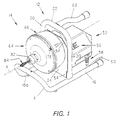
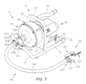
- FIGS 1 and 2 illustrate drain cleaning apparatus 10 comprising a frame 12 which supports a cable drum assembly 14 for rotation about a cable drum axis A.
- Frame 12 comprises a tubular metal base portion having laterally spaced apart legs 16 interconnected at their forward ends by a U-shaped bridging portion 18 which inclines upwardly and forwardly relative to legs 16.
- the frame further includes an inverted U-shaped tubular metal frame member having laterally spaced apart legs 20 welded to and extending upwardly from legs 16 of the base portion of the frame and having a bridging portion 22 between the upper ends of the legs, and a mounting and support plate 24 which extends between and is welded or otherwise secured to legs 20.
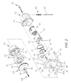
- Cable drum assembly 14 is supported on plate 24 for rotation about axis A by a bearing support member 26 which is welded on plate 24, bearing sleeves 28 and 30 received in axially opposite ends of member 26, and a drum shaft 32 rotatably supported by the bearing sleeves and interconnected with the drum assembly as set forth hereinafter.
- Drum shaft 32 is adapted to be driven by a reversible motor 34 through a pulley and endless belt unit including a pulley 36 mounted on and driven by motor shaft 38, a pulley 40 mounted on the inner end of drum shaft 32 and interconnected therewith such as by a flat so as to rotate the drum shaft, and an endless belt 42 trained about pulleys 36 and 40.
- Motor 34 is attached to a motor mounting plate 44 by means of a plurality of button head screws 46, and mounting plate 44 is secured to mounting and support plate 24 of the frame by carriage bolts 48 and nuts 50.
- the drive motor, pulleys and drive belt are enclosed in a housing 52 which is attached to support plate 24 by a plurality of threaded fasteners 54, and housing 52 supports a toggle switch unit 56 for controlling motor 34 and a flexible protective sleeve 58 through which motor power cord 60 extends for connection to a source of AC current.
- frame 12 includes a handle 62 which extends rearwardly over housing 52 and by which the apparatus can be carried.
- Cable drum assembly 14 comprises front and rear cable drum housing members 64 and 66, respectively, and an intermediate cable cartridge 68 in which, as will be appreciated from Figure 3, a drain cleaning snake or cable 70 is coiled about axis A.
- Rear housing member 66 includes a hub 72 which is internally threaded on the inner or rear end thereof to interengage with threaded axially outer end 32a of drum shaft 32 so as to mount the cable drum assembly on shaft 32 for rotation therewith.
- Rear housing 66 is further secured to drum shaft 32 by a flat head screw 73 which extends through an opening therefor in hub 72 and into a threaded bore in end 32a of the drum shaft.
- Rear housing member 66 further includes radially inwardly extending ribs 74 which axially slidably interengage with recesses 76 in the outer periphery of cartridge 68 so as to engage the latter with housing member 66 for rotation therewith.
- Cartridge 68 is axially retained in rear housing member 66 by front housing member 64 which is secured to housing member 66 by a plurality of headed fasteners 78 in the outer ends of ribs 74 and drum clips 79 mounted on front housing member 64 and providing bayonet slots for fasteners 78.
- Front housing member 64 has a forwardly extending hub 80 to which an exit collar 82 is secured by means of a set screw, not designated numerically, and cable 70 extends through the hub and exit collar drum from cartridge 68 and has a free or outer end 84 for entry into a drain or waste line to be cleaned. Accordingly, it will be appreciated that the hub and exit collar provide an opening at the front of cable drum assembly 14 through which the free end of the drain cleaning cable extends for entry into a drain to be cleaned.
- cable drum cartridge 68 includes an outer peripheral wall 86, a closed inner or rear end defined by a peripheral wall 88 extending radially inwardly from wall 86 and an axially forwardly extending peripheral wall 90 spaced radially inwardly from outer wall 86 and terminating in a cone-shaped forward end wall 92, and a front end defined by a peripheral wall 94 extending radially inwardly from outer wall 86.
- the radially inner end of wall 94 is spaced radially outwardly from cone-shaped wall 92 and provides a peripheral opening 96 therewith through which cable 70 extends for passage through hub 80 and exit collar 82 of the drum assembly.
- cable 70 is wound in the cartridge about axis A between the front and rear ends of the cartridge and, as a result of the bias of the spring metal from which the cable is constructed, is biased radially outwardly against wall 86 of the cartridge.
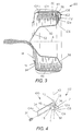
- cable 70 has an inner end 98 disposed adjacent the juncture between outer wall 86 and rear wall 88 of the cartridge housing and provided with a torque arm 100 which operates as set forth hereinafter to increase the torque applied to cable 70 in response to rotation of the drum assembly during operation of the drain cleaning apparatus.
- torque arm 100 is constructed from a strip of cold rolled steel and has a mounting end 102 by which the torque arm is attached to end 98 of the cable.
- the torque arm comprises an elongate, planar first leg 104 extending from mounting end 102, and the latter is defined by a pair of second legs 106 each of which is parallel to leg 104 and integrally interconnected therewith by a corresponding U-shaped bridging portion 108.
- Bridging portions 108 provide mounting end 102 of the torque arm with an axis 110 with respect to which legs 106 are spaced apart from one another and, preferably, the torque arm further includes a finger 112 axially between legs 106 and bridging portions 108 and which is integral with first leg 104 and extends perpendicular thereto and tangential to bridging portions 108.
- a nut or other block member 114 extends between first leg 104 and the free ends of second legs 106 and is securely fastened thereto such as by weldments 116.
- Block 114 is provided with a threaded opening 118 therethrough extending radially of axis 110 for receiving a threaded fastener 120, such as a set screw, by which the torque arm is removably mounted on end 98 of the drain cleaning cable.
- a threaded fastener 120 such as a set screw
- leg 104 of the torque arm is adjacent outer wall 86 of the cartridge housing and extends from the juncture between outer wall 86 and rear wall 88 to a point adjacent the juncture between the outer wall and front wall 94.
- the torque arm is biased radially outwardly by the resiliency and coiled condition of cable 70 in the cartridge housing and frictionally engages outer wall 86 along the length of leg 104 to front edge 104a thereof and into the bridging portions 108 at mounting end 102 of the torque arm.
- Finger 112 extends radially inwardly from mounting end 102 and engages rear wall 88 of the cartridge housing along upper or radially inner edge 112a of the finger.
- torque arm 100 resists sliding of cable 70 relative to the cartridge housing when an obstruction or the like is encountered by the leading end of the snake which is disposed in the drain or waste line being cleaned. While finger 112 contributes to the resistance to sliding, its primary purpose is to stabilize the torque against pivotal movement clockwise in Figure 3 about axis 110 when the radially outward bias on leg 104 by the cable is reduced, such as when the cable is nearly fully extended from the cartridge housing.
- the cold rolled steel strip of which the torque arm is constructed has a thickness of 1.52 mm (0.06 inch), a width of 19.05 mm (0.75 inch) and a length of 63.5 mm (2.50 inches) from axis 110 to edge 104a of leg 104.
- the curvature of bridging portions 106 has a radius of 5.58 mm (0.22 inch) with respect to axis 110
- finger 112 has a length of 17.52 mm (0.69 inch) from axis 110 to edge 112a of the finger.
- Each of the legs 106 and finger 112 have a width of 6.35 mm (0.25 inch) in the direction of axis 110.
- U-shaped portion 18 of the base of frame 12 includes a portion 18a extending horizontally across the front end of drum assembly 14 below exit collar 82 thereof, and a manually operable cable feed device 122 is mounted on frame portion 18a by means of a mounting bracket 124 to facilitate the selective feeding of drain cleaning cable 70 outwardly and inwardly relative to drum assembly 14.
- Cable feed device 122 corresponds structurally and functionally to the cable feed device disclosed in EP-A-0 894 906.
- Figures 5 and 6 in the present specification correspond respectively to Figures 2 and 4 in EP-A-0 894 906.
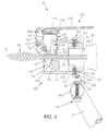
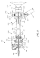
- cable feed device 122 comprises a tubular housing 126 having an axis coinciding with axis A of the apparatus and axially opposite front and rear ends 128 and 130, respectively.
- Housing 126 includes a wall 132 therein transverse to axis A and having a passage 134 for receiving cable 70.
- Wall 132 includes roll mounting nodes 136 on the front side thereof, and the feed device includes a pair of cable driving rolls 138 and 140 mounted on nodes 136 by socket head cap screws 142 and 144, respectively.
- the cap screws provide axes for rotation of the respective driving rolls, and each driving roll axis is skewed both horizontally and vertically relative to the housing axis.
- Driving rolls 138 and 140 have smooth outer surfaces 146 and 148, respectively, and the skewed mounting thereof provides for driving drain cleaning cable 70 in a well known manner when the cable is rotated and displaced against the driving rolls.
- Housing 126 further includes a radially extending bore 150 having an inner end which opens into cable passage 134 and which slidably and removably receives a cable drive actuating unit including a drive actuating roll support member 152.
- Support member 152 has a radially inner end on which a drive actuating roll 154 is mounted by means of a socket head cap screw 156 which provides an axis for the drive actuating roll, and an axially outer end on which an operating knob member 158 is mounted by way of a threaded stem 160 received in a threaded recess therefor in roll support member 152, not designated numerically.
- Operating knob member 158 is axially adjustable relative to roll support member 152 for adjusting the axial length of the drive actuating unit, and a compression spring 162 surrounds the roll support member between the radially outer end of bore 150 and the underside of operating knob member 158 to bias the drive actuating unit radially outwardly of the housing.
- Drive actuating roll 154 has a smooth outer surface 164 and, as will be appreciated from Figure 5, the driving rolls and actuator drive roll are equally spaced apart circumferentially about axis A. Further, drive actuating roll support member 152 supports drive actuating roll 154 in housing 12 for the axis of the drive actuating roll to be skewed horizontally with respect to axis A, preferably at the same angle as that of driving rolls 138 and 140 which, preferably, is 30° with respect to both the horizontal and vertical directions of the skew thereof.
- the drive actuating unit of feed device 122 is adapted to be displaced radially inwardly of housing 126 against the bias of spring 162 by means of an operating lever 166 which includes a mounting leg 168 and a handle portion 170 extending perpendicular thereto.
- the front end of housing 126 is provided with a pair of lever mounting ears 172, and mounting leg 168 of the lever is received between ears 172 and has a rolled tubular lower end 174 receiving a pivot pin 176 extending through openings therefor in cars 172 to provide a lever pivot axis transverse to and laterally spaced from axis A.
- Handle portion 170 extends across the outer surface of operating knob member 158 and is provided with a finger 178 which frictionally engages with the peripheral outer surface of the knob member to releasably hold the drive actuating unit in bore 150 and to restrain rotation of the operating knob member relative to drive actuating roll support member 152.
- mounting bracket 124 includes an L-shaped bracket plate having a vertical leg 180 and a horizontal leg 182 extending forwardly from the lower end thereof and secured to frame portion 18a such as by a pair of bolts 184 extending upwardly through openings therefor in frame portion 18a and into threaded engagement with nuts 185 welded on leg 182 of the bracket plate.
- Leg 180 is provided with an opening 186 coaxial with axis A, and the mounting bracket further includes an annular adaptor sleeve 188 mounted on the front side of leg 180 such as by welding and so as to be coaxial with axis A.
- Inner end 130 of housing 126 of the cable feed device axially receives adaptor sleeve 188 therein, and the housing is provided with diametrically opposed pairs of openings 190 adapted to be aligned with corresponding bores 192 in the radially outer side of adaptor sleeve 188. Openings 190 arc internally threaded to receive the threaded shanks of bolts 194 by which housing 126 and thus feed device 122 is removably mountable on the drain cleaning apparatus.
- drain cleaning cable feed device 122 is mounted on the outer end of a flexible guide tube assembly 196 having its inner end detachably connected to adaptor 188 of mounting bracket 124. More particularly, guide tube 196 comprises a flexible hose 198 having coupling arrangements 200 and 202 on the opposite ends of the hose and which respectively provide the axially outer and axially inner ends of the flexible guide tube.
- Coupling arrangement 200 comprises a ferrule axially received on the outer end of hose 198 and including an inner sleeve 206 extending axially inwardly of the hose, and a connector member 208 having a central flange 209, a recess 210 on one side thereof receiving ferrule 204, and an externally threaded sleeve 212 on the other side thereof.
- Coupling arrangement 200 further includes a gland ring 214 and a compression nut 216 by which ferrule 204 and thus the corresponding end of hose 198 is attached to connector member 208, and a tubular mounting collar 218 which is internally threaded at one end for threaded interengagement with externally threaded sleeve 212 of connector member 208.
- Mounting collar 218 is axially received in inner end 130 of housing 126 of the cable feed device and is provided with an outwardly open annular recess 220 which is adapted to receive the inner ends of fasteners 194 provided on housing 126 in diametrically opposed pairs.
- the inner ends of fasteners 194 and recess 220 are dimensioned for the fasteners to slide circumferentially in the recess, whereby an operator can rotate cable feed device 122 about the axis of the flexible guide tube.
- Coupling arrangement 202 comprises a mounting collar having an axially outer end 224 for receiving adaptor 188 of mounting bracket 124 and having an axially inner end which is necked in to provide a cradle 226 underlying the corresponding end of hose 198.
- a hose clamp 228 and fasteners 229 secure hose 198 to cradle 226 and thus the mounting collar.
- Collar 224 supports a spring biased mounting plunger 230 which includes a post 232 extending radially through an opening therefor in collar 224 and into one of the bores 192 in adaptor 188.
- the plunger includes an operating member 234 on the radially outer end of post 232, and a spring unit 236 normally biases post 232 radially inwardly of bore 192. Accordingly, it will be appreciated that the guide tube and cable feed device can readily be detached from the drain cleaning apparatus by pulling outwardly on operating member 234 to withdraw post 232 from bore 192 so as to free the mounting collar 224 for axial separation from adaptor 188.
- drain cleaning cable 70 is adapted to extend through the flexible hose and coupling arrangements and outwardly through feed device 122 which is operable in the manner described hereinabove to displace the cable axially in response to rotation of the cable drum assembly.
- Hose 198 can be of any desired length and, preferably, has a length of about 0.9 m (three feet) which advantageously enables the operator to hold feed device 122 in one hand and to flex the guide tube as is necessary to direct outer end 84 of the cable into a drain or waste line to be cleaned. Accordingly, the operator can perform a drain cleaning operation without having to physically touch the drain cleaning cable.
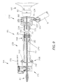
- Figure 9 illustrates a modification of the flexible guide tube shown in Figures 7 and 8 and, in this respect, illustrates a hand grip component 238 which replaces mounting collar 218 of the guide tube assembly shown in the latter figures.
- Hand grip 238 is a tubular metal member having an axial length and outer diameter to accommodate an operator's hand and is provided at one of the opposite ends thereof with internal threads 240 for threaded interengagement with externally threaded collar 212 of connector member 208.
- the other end of the hand grip is provided with a radially outwardly open circumferential recess 242 which receives and cooperates with fasteners 194 on the feed device housing to support the feed device for rotation about the axis of the guide tube as described hereinabove in connection with the embodiment of Figures 7 and 8.
Landscapes
- Engineering & Computer Science (AREA)
- Mechanical Engineering (AREA)
- Cleaning In General (AREA)
- Storing, Repeated Paying-Out, And Re-Storing Of Elongated Articles (AREA)
- Agricultural Machines (AREA)
Claims (14)
- Abflußrohrreinigungsvorrichtung mit einem Rahmen (12), einer von dem Rahmen (12) zur Rotation um eine Trommelachse (A) getragenen Kabeltrommel (14), wobei die Trommel (14) axial voneinander beabstandet ein Vorderende und ein Hinterende (94, 88) und eine Öffnung (96) durch das Vorderende (94) aufweist, einem auf der Trommel (14) um die Achse (A) aufgewickeltes Abflußrohrreinigungskabel (70), welches ein Ende (84) zum Durchführen durch die Öffnung (96) und in ein zu reinigendes Abflußrohr aufweist, einem von dem Rahmen (12) getragenen Antriebsmotor (34) zum Drehen der Trommel (14) und des Kabels (70), einer Führungsröhre (196) zum Aufnehmen des Endes (84) des Kabels (70), wobei die Führungsröhre ein inneres Ende und ein äußeres Ende aufweist und an einem Rahmenabschnitt (18a) befestigt ist, und mit einer Kabelzuführvorrichtung (122) zum selektiven axialen Verschieben des Kabels (70) relativ zu der Trommel (14) während der Rotation der Trommel (14) und des Kabels (70) um die Trommelachse (A),
dadurch gekennzeichnet,
daß die Führungsröhre (196) zum Lenken des äußeren Endes (84) des Kabels (70) in Richtung eines zu reinigenden Abflußrohres zwischen dem inneren und dem äußeren Ende flexibel ist, daß das innere Ende der Führungsröhre (196) an dem Rahmenabschnitt (18a) befestigt ist, welcher nach außen neben der Trommelöffnung (96) angeordnet ist, und daß die Kabelzuführvorrichtung (122) eine an dem äußeren Ende der Führungsröhre (196) angeordnete, manuell betreibbare Zuführungsvorrichtung (122) ist. - Abflußrohrreinigungsvorrichtung nach Anspruch 1, dadurch gekennzeichnet, daß die Zuführvorrichtung (122) ein Gehäuse (126), welches eine Gehäuseachse und einen sich axial durch dieses erstreckenden Durchgang (134) zum Aufnehmen des Kabels (70) aufweist, ein von dem Gehäuse (126) getragenes Kabelantriebsrollenmittel, ein von dem Gehäuse (126) getragenes Antriebsbetätigungsmittel zum radialen Verschieben des Kabels (70) gegen das Kabelantriebsrollenmittel, wobei das Antriebsbetätigungsmittel radial innere und äußere Enden aufweist, und ein schwenkbar an dem Gehäuse (126) angeordnetes Hebelmittel (166) zum Angreifen an dem äußeren Ende und radialen Verschieben des Antriebsbetätigungsmittels gegen das Kabel (70) aufweist.
- Abflußrohrreinigungsvorrichtung nach Anspruch 2, dadurch gekennzeichnet, daß es ein Mittel (162) zum Vorspannen des Antriebsbetätigungsmittels radial nach außen von dem Durchgang (134) aufweist.
- Abflußrohrreinigungsvorrichtung nach Anspruch 3, dadurch gekennzeichnet, daß das Kabelantriebsrollenmittel ein Paar von Kabelantriebsrollen (138, 140) aufweist, die jeweils zur Rotation um eine radial bezüglich der Öffnung (96) festgelegte Antriebsrollenachse an dem Gehäuse (126) angeordnet sind.
- Abflußrohrreinigungsvorrichtung nach Anspruch 4, dadurch gekennzeichnet, daß das Antriebsbetätigungsmittel eine das innere Ende desselben bildende Antriebsbetätigungsrolle (154) aufweist, die um eine Betätigungsrollenachse drehbar ist.
- Abflußrohrreinigungsvorrichtung nach Anspruch 5, dadurch gekennzeichnet, daß die Antriebsrollenachsen sowie die Betätigungsrollenachse bezüglich der Gehäuseachse schräg verlaufen und daß die Kabelantriebsrollen (138, 140) und die Betätigungsrolle (154) eine glatte äußere Oberfläche (146, 148, 164) aufweisen.
- Abflußrohrreinigungsvorrichtung nach Anspruch 1, dadurch gekennzeichnet, daß sie weiterhin eine Befestigungsklammer (124) auf dem Rahmenabschnitt (18a) aufweist, wobei die Führungsröhre (196) einen Schlauch (198) aus einem elastomeren Material mit einander gegenüberliegenden Enden aufweist, wobei das innere Ende der Führungsröhre (196) ein Kupplungselement (202) an einem der Enden des Schlauches (198) zum Verbinden des Schlauches (198) mit der Befestigungsklammer (124) aufweist und wobei das äußere Ende der Führungsröhre (196) ein Mittel am anderen Ende des Schlauches (198) aufweist zum Verbinden des Schlauches (198) mit der Zuführungsvorrichtung (122).
- Abflußrohrreinigungsvorrichtung nach Anspruch 7, dadurch gekennzeichnet, daß die Zuführungsvorrichtung (122) ein Gehäuse (126), welches eine Gehäuseachse und einen sich axial durch dieses erstreckenden Durchgang (134) zum Aufnehmen des Kabels (70) aufweist, ein von dem Gehäuse (126) getragenes Kabelantriebsrollenmittel (138, 140), ein von dem Gehäuse (126) getragenes Antriebsbetätigungsmittel zum radialen Verschieben des Kabels (70) gegen das Kabelantriebsrollenmittel, wobei das Antriebsbetätigungsmittel radial innere und äußere Enden aufweist, und ein schwenkbar an dem Gehäuse (126) angeordnetes Hebelmittel (166) zum Angreifen an dem äußeren Ende und radialen Verschieben des Antriebsbetätigungsmittels gegen das Kabel (70) aufweist.
- Abflußrohrreinigungsvorrichtung nach Anspruch 8, dadurch gekennzeichnet, daß das Kuppelelement (202) ein erstes Kuppelelement ist und daß das Mittel an dem anderen Ende des Schlauches (198) ein zweites Kuppelelement (200) aufweist und ein das zweite Kuppelelement (200) und das Gehäuse (126) verbindendes Mittel, so daß die Zuführvorrichtung (122) relativ zu dem Schlauch (198) verdrehbar ist.
- Abflußrohrreinigungsvorrichtung nach Anspruch 9, dadurch gekennzeichnet, daß das Gehäuse (126) einen rohrförmigen Endabschnitt mit einer Achse aufweist, der das zweite Kuppelelement (200) axial aufnimmt, und daß das das zweite Kuppelelement (200) und das Gehäuse (126) verbindende Mittel eine periphere Vertiefung (220) in dem zweiten Kuppelelement (200), die koaxial mit der Achse des Endbereichs ist, und eine Vielzahl von sich radial von dem Endabschnitt nach Innen in die Vertiefung (220) erstreckenden Stiften (194) aufweist.
- Abflußrohrreinigungsvorrichtung nach Anspruch 9, dadurch gekennzeichnet, daß das Kabelantriebsrollenmittel ein Paar von Kabelantriebsrollen (138, 140) aufweist, die jeweils zur Rotation um eine radial bezüglich der Öffnung (96) festgelegte Antriebsrollenachse an dem Gehäuse (126) angeordnet sind, aufweist und daß das Antriebsbetätigungsmittel eine das innere Ende desselben bildende Antriebsbetätigungsrolle (154) aufweist, die um eine Betätigungsrollenachse drehbar ist.
- Abflußrohrreinigungsvorrichtung nach Anspruch 11, dadurch gekennzeichnet, daß die Antriebsrollenachsen sowie die Betätigungsrollenachse bezüglich der Gehäuseachse schräg verlaufen, und daß die Kabelantriebsrollen (138, 140) und die Betätigungsrolle (154) eine glatte äußere Oberfläche (146, 148, 164) aufweisen.
- Abflußrohrreinigungsvorrichtung nach Anspruch 8, dadurch gekennzeichnet, daß das Mittel am anderen Ende des Schlauches (198) einen rohrförmigen Handgriff (238) aufweist, der ein mit dem anderen Ende des Schlauches (198) verbundenes, inneres Ende und an einem äußeren Ende ein Mittel zum Verbinden des äußeren Endes des Handgriffes (238) und des Gehäuses (126) aufweist, so daß die Zuführvorrichtung (122) relativ zu dem Schlauch (198) verdrehbar ist.
- Abflußrohrreinigungsvorrichtung nach Anspruch 13, dadurch gekennzeichnet, daß das Gehäuse (126) einen rohrförmigen Endabschnitt mit einer Achse aufweist, der das äußere Ende des Handgriffs (238) axial aufnimmt, und daß das das äußere Ende des Handgriffs (238) und das Gehäuse (126) verbindende Mittel eine periphere Vertiefung (242) in dem äußeren Ende des Handgriffs (238), die koaxial mit der Achse des Endbereichs ist, und eine Vielzahl von sich radial von dem Endabschnitt nach Innen in die Vertiefung (242) erstreckenden Stiften (208) aufweist.
Priority Applications (1)
| Application Number | Priority Date | Filing Date | Title |
|---|---|---|---|
| EP00202480A EP1041207A3 (de) | 1998-07-16 | 1999-04-02 | Abwasserleitungsreinigungsgerät |
Applications Claiming Priority (2)
| Application Number | Priority Date | Filing Date | Title |
|---|---|---|---|
| US116225 | 1998-07-16 | ||
| US09/116,225 US6009588A (en) | 1998-07-16 | 1998-07-16 | Drain cleaning apparatus |
Related Child Applications (1)
| Application Number | Title | Priority Date | Filing Date |
|---|---|---|---|
| EP00202480A Division EP1041207A3 (de) | 1998-07-16 | 1999-04-02 | Abwasserleitungsreinigungsgerät |
Publications (3)
| Publication Number | Publication Date |
|---|---|
| EP0952264A2 EP0952264A2 (de) | 1999-10-27 |
| EP0952264A3 EP0952264A3 (de) | 2000-05-10 |
| EP0952264B1 true EP0952264B1 (de) | 2001-08-22 |
Family
ID=22365970
Family Applications (2)
| Application Number | Title | Priority Date | Filing Date |
|---|---|---|---|
| EP00202480A Withdrawn EP1041207A3 (de) | 1998-07-16 | 1999-04-02 | Abwasserleitungsreinigungsgerät |
| EP99630032A Expired - Lifetime EP0952264B1 (de) | 1998-07-16 | 1999-04-02 | Abwasserleitungsreinigungsvorrichtung |
Family Applications Before (1)
| Application Number | Title | Priority Date | Filing Date |
|---|---|---|---|
| EP00202480A Withdrawn EP1041207A3 (de) | 1998-07-16 | 1999-04-02 | Abwasserleitungsreinigungsgerät |
Country Status (8)
| Country | Link |
|---|---|
| US (3) | US6009588A (de) |
| EP (2) | EP1041207A3 (de) |
| JP (1) | JP4142206B2 (de) |
| CN (2) | CN1181933C (de) |
| BR (1) | BR9901371A (de) |
| CA (1) | CA2246077C (de) |
| DE (2) | DE952264T1 (de) |
| ES (1) | ES2162513T3 (de) |
Families Citing this family (89)
| Publication number | Priority date | Publication date | Assignee | Title |
|---|---|---|---|---|
| US6470525B1 (en) * | 1999-11-30 | 2002-10-29 | Arthur A. Silverman | Drain cleaning apparatus having remote power feed |
| US6343398B1 (en) * | 2000-04-13 | 2002-02-05 | General Wire Spring Company | Drain cleaning apparatus with feed control |
| US6637064B2 (en) | 2001-01-02 | 2003-10-28 | Lee H. Silverman | Drain cleaning apparatus with remotely adjustable feed control |
| US6626195B1 (en) * | 2001-03-16 | 2003-09-30 | Aqua Dynamics, Inc. | High pressure tube cleaning apparatus |
| US7178534B2 (en) * | 2001-03-16 | 2007-02-20 | Aquadynamics, Inc. | High pressure tube cleaning apparatus |
| US6618891B2 (en) | 2001-08-10 | 2003-09-16 | Masco Corporation | Rotary drum release for a drain cleaning machine |
| US6760948B2 (en) | 2001-08-16 | 2004-07-13 | Masco Corporation | Snap latch drum release for a drain cleaning machine |
| US6618892B2 (en) | 2001-09-27 | 2003-09-16 | Masco Corporation | Socket latch drum release for a drain cleaning machine |
| DE10227204B4 (de) * | 2002-06-18 | 2005-01-05 | Rothenberger Ag | Verfahren zum Reinigen von Rohrleitungen und Rohrreinigungsmaschine hierfür |
| US7367077B2 (en) * | 2004-03-04 | 2008-05-06 | Emerson Electric Co. | Drain cleaning apparatus |
| US7478451B2 (en) * | 2004-03-04 | 2009-01-20 | Emerson Electric Co. | Feed control device for plumbing tools |
| US7685669B2 (en) * | 2004-03-04 | 2010-03-30 | Emerson Electric Co. | Feed control device for plumbing tools |
| DE102004020686B3 (de) | 2004-04-28 | 2006-01-05 | Se Tylose Gmbh & Co. Kg | Verfahren und Vorrichtung zur Mahlung von Cellulose |
| USD509929S1 (en) * | 2004-08-10 | 2005-09-20 | Emerson Electric Co. | Drain cleaner |
| US7269874B2 (en) * | 2005-03-04 | 2007-09-18 | Yoen Hung | Cleaning device for cleaning ducts and pipes |
| WO2006112848A1 (en) * | 2005-04-14 | 2006-10-26 | Emerson Electric Co. | Feed control device for plumbing tools |
| US7419038B2 (en) * | 2005-05-31 | 2008-09-02 | Great Stuff, Inc. | Reel and reel housing |
| DE102006006602A1 (de) | 2006-02-14 | 2007-08-16 | Rothenberger Ag | Rohrreinigungsmaschine mit einer Trommel für eine Federwelle |
| US8312572B2 (en) | 2006-10-05 | 2012-11-20 | Robert Scott Heffner | Telescoping plumbing device and method |
| US20080098544A1 (en) * | 2006-10-30 | 2008-05-01 | Emerson Electric Co. | Drain cleaning machine with added stability, portability and maneuverability |
| US20080148503A1 (en) * | 2006-12-21 | 2008-06-26 | Emerson Electric Co. | Cable feeding device with indicator |
| USD579612S1 (en) * | 2007-04-26 | 2008-10-28 | Emerson Electric Co. | Frame for a drain cleaning machine |
| US20090293214A1 (en) * | 2007-05-09 | 2009-12-03 | Ackerman Bryan L | Drain clog remover and shaft usable therewith |
| US20090056042A1 (en) * | 2007-08-30 | 2009-03-05 | Daniel Pena | Cleaning tool |
| US8615837B2 (en) * | 2008-02-27 | 2013-12-31 | Electric Eel Manufacturing Company, Inc. | Motorized drain cleaning machine with speed controller |
| CN101524965B (zh) * | 2008-03-03 | 2011-04-06 | 株洲南车时代电气股份有限公司 | 一种电力机车过电压抑制吸收系统 |
| KR100960654B1 (ko) * | 2008-03-07 | 2010-06-07 | (주)아리수텍 | 배관용 스케일 제거기 |
| DE202008018563U1 (de) | 2008-03-25 | 2015-11-03 | Rothenberger Ag | Reinigungsgerät für die Reinigung von Rohrleitungen |
| DE102008015532B4 (de) | 2008-03-25 | 2014-08-07 | Rothenberger Ag | Reinigungsgerät für die Reinigung von Rohrleitungen |
| US8176593B2 (en) | 2008-05-22 | 2012-05-15 | Emerson Electric Co. | Drain cleaning apparatus with electronic cable monitoring system |
| CA2722769A1 (en) * | 2008-05-22 | 2009-11-26 | Emerson Electric Co. | Drain cleaning apparatus with electronic cable monitoring system |
| US8046862B2 (en) * | 2008-08-08 | 2011-11-01 | Emerson Electric Co. | Drain cleaning apparatus with electronic cable counter |
| US7889980B2 (en) | 2008-11-21 | 2011-02-15 | Emerson Electric Co. | Graphical representation of enclosed inspection area |
| US8739968B2 (en) * | 2008-12-02 | 2014-06-03 | S.C. Johnson & Son, Inc. | Drain clog remover |
| AU2009322947A1 (en) * | 2008-12-02 | 2011-06-30 | S. C. Johnson & Son, Inc. | Drain clog remover |
| USD626818S1 (en) * | 2009-04-28 | 2010-11-09 | Great Stuff, Inc. | Support structure for a reel |
| ES2390213T3 (es) | 2009-07-24 | 2012-11-07 | Rothenberger Ag | Equipo de limpieza para la limpieza de tuberías |
| US8887343B2 (en) * | 2010-03-12 | 2014-11-18 | Stoneage, Inc. | System for propelling a coil clad hose and method thereof |
| US8878397B2 (en) | 2010-08-31 | 2014-11-04 | Great Stuff, Inc. | Electrical cord reel with control system to limit overheating |
| DE102012112599A1 (de) * | 2011-12-21 | 2013-06-27 | Emerson Electric Co. | Vorschubsteuersperre für manuell bedienten Abflussreiniger |
| US9550649B2 (en) | 2013-05-30 | 2017-01-24 | Stoneage, Inc. | Apparatus for propelling a coil clad hose |
| CN103711187A (zh) * | 2013-12-20 | 2014-04-09 | 柳州博泽科技有限公司 | 一种下水管道清理装置 |
| CN103711186A (zh) * | 2013-12-20 | 2014-04-09 | 柳州博泽科技有限公司 | 一种下水管道高压水清理装置 |
| US10071401B2 (en) * | 2014-12-23 | 2018-09-11 | Ridge Tool Company | Feed control device for plumbing tools |
| CN113026928A (zh) | 2015-12-09 | 2021-06-25 | 米沃奇电动工具公司 | 排水清洁器 |
| US10851868B2 (en) * | 2016-03-18 | 2020-12-01 | Ridge Tool Company | Motor dampener and drive train for plumbing tools |
| US10646905B2 (en) * | 2016-03-18 | 2020-05-12 | Ridge Tool Company | Modular guide hose system for plumbing tools |
| US10626593B2 (en) | 2016-04-05 | 2020-04-21 | Black & Decker Inc. | Powered drain auger |
| US10240330B2 (en) * | 2016-05-31 | 2019-03-26 | Brasscraft Manufacturing Company | Compact drain snake |
| CN113482139B (zh) | 2016-07-27 | 2023-06-06 | 米沃奇电动工具公司 | 排水管清理器和用于排水管清理器的缆绳进给控制机构 |
| US11103900B2 (en) | 2016-09-29 | 2021-08-31 | Ken Beyer | Drain servicing assembly |
| US10704250B2 (en) | 2016-10-28 | 2020-07-07 | Milwaukee Electric Tool Corporation | Sewer cleaning machine |
| US10465372B2 (en) | 2016-11-24 | 2019-11-05 | Ridge Tool Company | Drain cleaning tools |
| EP3327211B1 (de) | 2016-11-24 | 2019-10-30 | Ridge Tool Company | Ablaufreinigungswerkzeuge |
| EP4123096B1 (de) | 2016-11-28 | 2024-07-17 | Milwaukee Electric Tool Corporation | Abflussreiniger |
| US20180147713A1 (en) * | 2016-11-30 | 2018-05-31 | Ridge Tool Company | Hybrid power tools |
| USD830806S1 (en) | 2017-02-15 | 2018-10-16 | Black & Decker Inc. | Drain auger |
| CN106996142A (zh) * | 2017-05-25 | 2017-08-01 | 上海澄泓管道机器人有限公司 | 一种管道机器人柔性管的分隔机构 |
| CA2978115A1 (en) * | 2017-08-25 | 2019-02-25 | David EMSLIE | Novel apparatus for unclogging drains |
| US10519646B2 (en) | 2017-10-27 | 2019-12-31 | Tti (Macao Commercial Offshore) Limited | Cable feed mechanism for a drain cleaner |
| CN108005226B (zh) * | 2017-11-20 | 2023-04-28 | 郑州中原科技工程研究院有限公司 | 管道清淤机中清淤缆固定用滚筒 |
| US11426776B2 (en) * | 2017-11-29 | 2022-08-30 | Ridge Tool Company | Mechanism for retention of multiple apparatus on plumbing tools |
| US10646906B2 (en) * | 2017-11-29 | 2020-05-12 | Ridge Tool Company | Mechanism for retention of multiple apparatus on plumbing tools |
| US11846528B2 (en) * | 2017-11-30 | 2023-12-19 | Ridge Tool Company | Systems and methods for identifying points of interest in pipes or drain lines |
| DE102018220546B4 (de) | 2017-11-30 | 2022-10-13 | Ridge Tool Company | Systeme und verfahren zum identifizieren von punkten von interesse in röhren oder abflussleitungen |
| CN111417470B (zh) * | 2017-12-14 | 2023-03-07 | 里奇工具公司 | 用于清洁使用、存储和运输的分段式下水道清洁线缆系统 |
| WO2019136362A1 (en) * | 2018-01-05 | 2019-07-11 | Milwaukee Electric Tool Corporation | Sewer cleaning machine |
| US11505229B2 (en) | 2018-04-13 | 2022-11-22 | Milwaukee Electric Tool Corporation | Tool support |
| CN108571043B (zh) * | 2018-05-12 | 2020-05-05 | 徐佩登 | 一种可拆卸的便于疏通的下水装置 |
| CN216728634U (zh) * | 2018-08-10 | 2022-06-14 | 米沃奇电动工具公司 | 排水管清洁机 |
| US11313114B2 (en) | 2018-09-11 | 2022-04-26 | Milwaukee Electric Tool Corporation | Drain cleaner |
| US12467248B2 (en) * | 2019-01-28 | 2025-11-11 | Ridge Tool Company | Powered drain cleaner with flex shaft |
| WO2020214641A1 (en) | 2019-04-16 | 2020-10-22 | Ridge Tool Company | Handheld drain cleaning machine with bipod support |
| US11905698B2 (en) | 2019-04-19 | 2024-02-20 | Milwaukee Electric Tool Corporation | Feed mechanism for a drain cleaner assembly |
| EP4624064A3 (de) | 2019-05-15 | 2025-12-17 | Milwaukee Electric Tool Corporation | Abflussreinigungsvorrichtung |
| EP4650539A2 (de) | 2019-06-10 | 2025-11-19 | Milwaukee Electric Tool Corporation | Transportable maschine mit einem schienensystem |
| CN114423533B (zh) * | 2019-09-30 | 2024-01-23 | 米沃奇电动工具公司 | 排水管清洁机器的电机控制 |
| WO2021067926A1 (en) | 2019-10-03 | 2021-04-08 | Milwaukee Electric Tool Corporation | Drain cleaner cable decoupler tool |
| US12134115B2 (en) | 2020-02-12 | 2024-11-05 | Milwaukee Electric Tool Corporation | Drain cleaning machine |
| DE102021201374A1 (de) * | 2020-02-14 | 2021-08-19 | Jetter Pro, Inc. | Angetriebener abflussreiniger mit flexiblem schaft |
| CN111268318B (zh) * | 2020-03-09 | 2021-04-06 | 南京溧水高新创业投资管理有限公司 | 一种下水道自动清理垃圾垃圾桶 |
| WO2022072557A1 (en) * | 2020-09-29 | 2022-04-07 | Milwaukee Electric Tool Corporation | Drain cleaner |
| EP4015680B1 (de) | 2020-12-18 | 2025-08-27 | Saurer Intelligent Technology AG | Spinnstelle einer luftspinnmaschine und verfahren zum reinigen eines garnbildungselements |
| US20230151600A1 (en) * | 2021-11-15 | 2023-05-18 | Emerson Professional Tools, LLC. | Sheathed flexible shaft drain cleaner |
| WO2024012466A1 (zh) * | 2022-07-12 | 2024-01-18 | 杭州巨星科技股份有限公司 | 一种疏通器 |
| USD1000734S1 (en) | 2022-10-27 | 2023-10-03 | Emerson Professional Tools, Llc | Drain cleaner |
| CN115971174A (zh) * | 2022-12-13 | 2023-04-18 | 重庆海特汽车排气系统有限公司 | 一种汽车排气管清洁装置 |
| US20240240442A1 (en) * | 2023-01-12 | 2024-07-18 | Nick Sphar | Cable Machine and Jet Line Combination Device |
| CN116007813B (zh) * | 2023-03-21 | 2025-09-16 | 安徽快通管道清洗科技有限公司 | 一种管道疏通机用疏通力临界值检测装置 |
Family Cites Families (94)
| Publication number | Priority date | Publication date | Assignee | Title |
|---|---|---|---|---|
| US1076870A (en) * | 1912-06-15 | 1913-10-28 | Benjamin Dahl | Conduit fish-wire machine. |
| US2090174A (en) | 1935-08-07 | 1937-08-17 | Albright William Fredrick | Flexible drive shaft |
| US2167268A (en) | 1936-10-24 | 1939-07-25 | George J Sanger | Rotary sewer cleaning machine |
| US2272387A (en) * | 1938-06-09 | 1942-02-10 | Earl M Myers | Clearway for clogged ducts |
| US2318172A (en) | 1939-07-22 | 1943-05-04 | Long Hugh | Universal tool |
| US2267493A (en) | 1940-08-05 | 1941-12-23 | Clotz Edward | Sewer cleaning machine |
| US2355733A (en) * | 1941-03-15 | 1944-08-15 | Buys | Pipe cleaning device |
| US2431089A (en) * | 1943-12-27 | 1947-11-18 | Robert F Therrien | Duct interior cleaning means |
| US2467849A (en) | 1944-06-14 | 1949-04-19 | Brien O | Portable electric rotary drain cleaner |
| US2468490A (en) | 1945-03-15 | 1949-04-26 | Joseph John Di | Pipe cleaning power cable feeder |
| US2600707A (en) | 1949-04-15 | 1952-06-17 | James E Turnbaugh | Flexible rotary reaming apparatus |
| US2769191A (en) | 1954-01-22 | 1956-11-06 | Marco Products Co | Plumber's tool |
| US3007186A (en) * | 1955-02-10 | 1961-11-07 | H D Conkey & Company | Sewer cleaning machines |
| US2926372A (en) * | 1957-02-21 | 1960-03-01 | H D Conkey & Company | Sewer cleaning machine |
| US2953799A (en) | 1959-03-23 | 1960-09-27 | Jimmie D Arnold | Pipe cleaning machine and cable feeding mechanism therefor |
| US3093854A (en) | 1960-06-13 | 1963-06-18 | Silverman Abraham | Machine for automatically feeding a plumber's snake |
| US3159861A (en) * | 1963-04-08 | 1964-12-08 | Dominick C Sarcone | Sewer cleaning machine |
| US3224024A (en) | 1964-03-23 | 1965-12-21 | Marco Products Co | Feed means for plumbers' tool |
| US3206782A (en) | 1964-04-27 | 1965-09-21 | John H Larsen | Plumber's snake device |
| US3268937A (en) * | 1964-06-01 | 1966-08-30 | Burton J Bollinger | Power driven plumber snake |
| US3283353A (en) | 1964-10-30 | 1966-11-08 | Bruce A Kirk | Plumber's snake unit |
| US3329044A (en) | 1965-10-04 | 1967-07-04 | Singer Louis | Cable handling device |
| US3370599A (en) * | 1965-10-21 | 1968-02-27 | Flexible Inc | Sewer cleaning apparatus with rotary hydraulic cleaning tool |
| US3394599A (en) | 1966-06-23 | 1968-07-30 | Council A. Tucker | Positive feed advancing mechanism |
| US3449782A (en) | 1967-09-15 | 1969-06-17 | Lawrence Irwin F | Grip handle chuck |
| US3451089A (en) | 1967-11-06 | 1969-06-24 | Conco Inc | Conduit cleaning apparatus |
| US3444578A (en) | 1967-12-12 | 1969-05-20 | Charles B Caperton | Manhole brace for sewer rod guide tube |
| US3612487A (en) | 1968-09-24 | 1971-10-12 | William E Raney | Device for pushing and pulling implements, including cables, into and from conduits and the like |
| US3776179A (en) | 1968-09-24 | 1973-12-04 | W Raney | Device for pushing and pulling implements, including cables, into and from conduits and the like |
| US3497899A (en) | 1969-03-13 | 1970-03-03 | Charles B Caperton | Manhole brace for sewer rod guide tube |
| US3609788A (en) | 1969-08-11 | 1971-10-05 | Lawrence Irwin F | Plumbers' tool |
| US3691583A (en) | 1971-01-06 | 1972-09-19 | Gen Wire Spring Co | Sewer augering machine |
| US3673627A (en) | 1971-06-25 | 1972-07-04 | Charles B Caperton | Drive for rodding machine |
| US3703015A (en) | 1971-08-25 | 1972-11-21 | Lester H Naeve | Conduit cleaning apparatus |
| US3809366A (en) | 1973-04-26 | 1974-05-07 | S Crees | Apparatus for drawing conductor wires through conduits |
| US3882565A (en) | 1973-11-30 | 1975-05-13 | Lawrence F Irwin | Spring feed device |
| JPS50109466A (de) | 1974-02-06 | 1975-08-28 | ||
| JPS50139471A (de) | 1974-04-24 | 1975-11-07 | ||
| US3897602A (en) | 1974-08-26 | 1975-08-05 | Richard N Waterbury | Pipe cleanout accessory |
| US3958293A (en) * | 1974-08-26 | 1976-05-25 | Augerscope, Inc. | Pipe cleaning machine |
| US3928885A (en) | 1975-01-27 | 1975-12-30 | Roto Rooter Corp | Pipe cleaning machine and cable retrieving mechanism therefor |
| JPS52112266A (en) | 1976-03-17 | 1977-09-20 | Hitachi Ltd | Function switch circuit of digital circuit |
| US4287630A (en) | 1978-05-15 | 1981-09-08 | Thomas Perez | Pipe cleaning apparatus |
| US4153966A (en) | 1978-06-12 | 1979-05-15 | Lawrence Irwin F | Spring feed device |
| JPS5539283A (en) | 1978-09-16 | 1980-03-19 | Sato Chiyuukichi | Cleaning device of inside of pipe |
| US4218802A (en) | 1979-03-14 | 1980-08-26 | Emerson Electric Co. | Drain cleaning apparatus |
| US4291429A (en) | 1979-10-03 | 1981-09-29 | Robert Servadio | Drill attachment |
| US4395791A (en) * | 1980-03-03 | 1983-08-02 | Lawrence Irwin F | Spring feeding mechanism |
| JPS603588B2 (ja) | 1980-10-23 | 1985-01-29 | 株式会社安田工業所 | 排水管等の掃除機 |
| DE3109876A1 (de) | 1981-03-14 | 1982-09-30 | Rothenberger GmbH & Co Werkzeuge-Maschinen KG, 6000 Frankfurt | Rohrreinigungsmaschine mit einem behaelter fuer die aufnahme von reinigungsspiralen unterschiedlicher durchmesser |
| US4364139A (en) | 1981-05-07 | 1982-12-21 | Emerson Electric Co. | Drum type sewer cleaner |
| USD271436S (en) | 1981-06-26 | 1983-11-15 | Emerson Electric Co. | Sewer cleaning machine |
| JPS5849828A (ja) | 1981-09-18 | 1983-03-24 | Matsushita Electric Ind Co Ltd | 空燃比制御装置 |
| GB2117078B (en) * | 1982-03-16 | 1985-04-03 | Yi Wah Kwok Mina | Drain cleaning device |
| GB2122712A (en) * | 1982-06-10 | 1984-01-18 | Pennwalt Ltd | Method and apparatus for axially feeding a flexible shaft along a pipe with simultaneous rotation of the shaft |
| US4580306A (en) | 1984-01-19 | 1986-04-08 | Lawrence Irwin F | Waste line cleanout apparatus |
| US4686732A (en) * | 1984-01-19 | 1987-08-18 | Lawrence Irwin F | Waste line cleanout apparatus |
| US4570281A (en) * | 1984-03-22 | 1986-02-18 | Boelens David A | Rotary drain cleaner |
| US4617693A (en) * | 1984-08-06 | 1986-10-21 | Meyer Marjorie A | Drain pipe cleaning tool |
| US4611360A (en) | 1984-11-15 | 1986-09-16 | Lawrence Irwin F | Pipe cleaning machine |
| CN85200011U (zh) * | 1985-04-01 | 1986-03-12 | 北京缝纫机一厂 | 自动管道清理机 |
| US4773113A (en) | 1985-10-02 | 1988-09-27 | Russell V Lee | Multiple use cleaning apparatus |
| US4716613A (en) | 1986-03-25 | 1988-01-05 | Lawrence Irwin F | Pipe cleaning machine |
| US5181668A (en) | 1987-09-07 | 1993-01-26 | Osaka Gas Co., Ltd. | Apparatus for running a wire through a pipe |
| US4819292A (en) | 1987-10-13 | 1989-04-11 | Kerr Stanton W | Transmission device for plumbing snakes |
| US4763374A (en) | 1987-12-07 | 1988-08-16 | Lewisan Products, Inc. | Powered drain cleaner |
| US4837887A (en) | 1988-02-02 | 1989-06-13 | Mclaughlin Thomas L | Power cleaning apparatus |
| US4914775A (en) * | 1988-12-19 | 1990-04-10 | Emerson Electric Co. | Retainer mechanism for drain cleaner drum |
| US4956889A (en) * | 1989-07-03 | 1990-09-18 | Emerson Electric Co. | Portable drain cleaning apparatus |
| US5107568A (en) * | 1989-09-14 | 1992-04-28 | Steamatic, Inc. | Duct sweeper |
| US5029356A (en) | 1989-09-25 | 1991-07-09 | General Wire Spring Company | Sewer augering apparatus |
| US5193242A (en) | 1989-12-11 | 1993-03-16 | Lawrence Irwin F | Wasteline cleanout apparatus |
| US5031276A (en) | 1990-02-20 | 1991-07-16 | Emerson Electric Co. | Drain cleaning machine |
| US5031263A (en) | 1990-02-20 | 1991-07-16 | Emerson Electric Co. | Drain cleaning machine |
| US5235718A (en) | 1991-10-24 | 1993-08-17 | Goodway Tools Corporation | Tube cleaning apparatus |
| US5239724A (en) | 1992-01-30 | 1993-08-31 | Spartan Tool | Mechanism for advancing a rotating cylindrical member |
| CN2117218U (zh) * | 1992-03-09 | 1992-09-30 | 卜庆德 | 手动管道疏通器 |
| US5222270A (en) | 1992-03-12 | 1993-06-29 | Spartan Tool, A Div. Of Heico, Inc. | Electromagnetic motor brake unit for rotary drain and sewer router |
| US5199129A (en) | 1992-03-24 | 1993-04-06 | Spartan Tool, A Div. Of Heico, Inc. | Torque monitoring system for rotary drain and sewer cleaning apparatus |
| US5309595A (en) | 1992-09-24 | 1994-05-10 | Spartan Tool Div. Of Pettibone Corp. | Drain cleaning apparatus |
| US5265301A (en) | 1992-11-02 | 1993-11-30 | Lawrence Irwin F | Drain cleaning apparatus |
| US5335388A (en) | 1993-04-13 | 1994-08-09 | Spartan Tool Div. Of Pettibone Corp. | Cutter assembly for conduit cleaner |
| US5333448A (en) | 1993-04-13 | 1994-08-02 | Spartan Tool Div. Of Pettibone Corp. | Fluid control nozzle for conduit cleaner |
| US5379476A (en) | 1993-04-13 | 1995-01-10 | Spartan Tool Div. Of Pettibone Corp. | Skid assembly for conduit cleaner |
| US5329662A (en) | 1993-04-13 | 1994-07-19 | Spartan Tool Div. Of Pettibone Corp. | Manipulator for conduit cleaner |
| CN2180348Y (zh) * | 1994-02-03 | 1994-10-26 | 北京新星机械厂 | 全自动型管道清理机 |
| US5390389A (en) | 1994-05-16 | 1995-02-21 | Emerson Electric Company | Wheeled load carrier |
| US5414888A (en) | 1994-06-24 | 1995-05-16 | Augerscope, Inc. | Grip handle chuck |
| US5535473A (en) | 1994-12-05 | 1996-07-16 | Maniar; Mark A. | Drain cleaning apparatus |
| CN2224676Y (zh) * | 1995-01-11 | 1996-04-17 | 鲍兴民 | 滚桶式手动管道疏通机 |
| US5507062A (en) | 1995-03-24 | 1996-04-16 | Spartan Tool Div. Of Pettibone Corp. | Sealing structure on a mechanism for advancing a rotating cylindrical member |
| US5618123A (en) | 1995-08-11 | 1997-04-08 | Pettibone Corporation | Coupling device for sewer and drain cleaning cable |
| US5640736A (en) | 1995-09-12 | 1997-06-24 | Pettibone Corporation | Power feed device for hand held drain and sewer cleaner |
| US6003842A (en) * | 1995-10-06 | 1999-12-21 | Hug; Hanspeter | Installation for putting in electrical cable for indoor installations |
-
1998
- 1998-07-16 US US09/116,225 patent/US6009588A/en not_active Expired - Lifetime
- 1998-09-30 CA CA002246077A patent/CA2246077C/en not_active Expired - Fee Related
-
1999
- 1999-04-02 DE DE0952264T patent/DE952264T1/de active Pending
- 1999-04-02 EP EP00202480A patent/EP1041207A3/de not_active Withdrawn
- 1999-04-02 ES ES99630032T patent/ES2162513T3/es not_active Expired - Lifetime
- 1999-04-02 DE DE69900223T patent/DE69900223T2/de not_active Expired - Lifetime
- 1999-04-02 EP EP99630032A patent/EP0952264B1/de not_active Expired - Lifetime
- 1999-04-20 BR BR9901371A patent/BR9901371A/pt not_active IP Right Cessation
- 1999-05-04 CN CNB991053990A patent/CN1181933C/zh not_active Expired - Fee Related
- 1999-05-04 CN CNB2004100904854A patent/CN1315588C/zh not_active Expired - Lifetime
- 1999-05-27 JP JP14749099A patent/JP4142206B2/ja not_active Expired - Fee Related
- 1999-12-13 US US09/459,587 patent/US6243905B1/en not_active Expired - Lifetime
-
2001
- 2001-07-16 US US09/906,178 patent/US6412136B1/en not_active Expired - Lifetime
Also Published As
| Publication number | Publication date |
|---|---|
| US6009588A (en) | 2000-01-04 |
| CA2246077C (en) | 2002-06-18 |
| JP4142206B2 (ja) | 2008-09-03 |
| CN1181933C (zh) | 2004-12-29 |
| CN1242265A (zh) | 2000-01-26 |
| EP0952264A3 (de) | 2000-05-10 |
| DE69900223T2 (de) | 2002-05-08 |
| DE69900223D1 (de) | 2001-09-27 |
| CN1315588C (zh) | 2007-05-16 |
| EP1041207A2 (de) | 2000-10-04 |
| US6243905B1 (en) | 2001-06-12 |
| BR9901371A (pt) | 2000-03-21 |
| JP2000042506A (ja) | 2000-02-15 |
| CA2246077A1 (en) | 2000-01-16 |
| US6412136B1 (en) | 2002-07-02 |
| DE952264T1 (de) | 2000-04-06 |
| CN1637214A (zh) | 2005-07-13 |
| EP0952264A2 (de) | 1999-10-27 |
| ES2162513T3 (es) | 2001-12-16 |
| EP1041207A3 (de) | 2001-02-07 |
Similar Documents
| Publication | Publication Date | Title |
|---|---|---|
| EP0952264B1 (de) | Abwasserleitungsreinigungsvorrichtung | |
| US6615436B1 (en) | Powered drain cleaner | |
| CA2280343C (en) | Feed control devices for hand operated drain cleaning tools | |
| US5901401A (en) | Feed control device for plumbing tools | |
| US6637064B2 (en) | Drain cleaning apparatus with remotely adjustable feed control | |
| US5640736A (en) | Power feed device for hand held drain and sewer cleaner | |
| US6360397B1 (en) | Feed control device for plumbing apparatus | |
| EP0786564B1 (de) | Reinigungsvorrichtung für Abwasserleitungen | |
| JPS6159190B2 (de) | ||
| US4716613A (en) | Pipe cleaning machine | |
| JPH028094B2 (de) | ||
| US7827647B2 (en) | Automatic tube/conduit cleaning system | |
| HK1000559B (en) | The drain cleaning apparatus | |
| US20220098849A1 (en) | Drain cleaner | |
| US3086234A (en) | Power driven snake canister | |
| CN220760409U (zh) | 排水管清理器 |
Legal Events
| Date | Code | Title | Description |
|---|---|---|---|
| PUAI | Public reference made under article 153(3) epc to a published international application that has entered the european phase |
Free format text: ORIGINAL CODE: 0009012 |
|
| AK | Designated contracting states |
Kind code of ref document: A2 Designated state(s): DE ES GB IT NL |
|
| AX | Request for extension of the european patent |
Free format text: AL;LT;LV;MK;RO;SI |
|
| ITCL | It: translation for ep claims filed |
Representative=s name: RICCARDI SERGIO & CO. |
|
| TCNL | Nl: translation of patent claims filed | ||
| PUAL | Search report despatched |
Free format text: ORIGINAL CODE: 0009013 |
|
| DET | De: translation of patent claims | ||
| AK | Designated contracting states |
Kind code of ref document: A3 Designated state(s): AT BE CH CY DE DK ES FI FR GB GR IE IT LI LU MC NL PT SE |
|
| AX | Request for extension of the european patent |
Free format text: AL;LT;LV;MK;RO;SI |
|
| 17P | Request for examination filed |
Effective date: 20000902 |
|
| GRAG | Despatch of communication of intention to grant |
Free format text: ORIGINAL CODE: EPIDOS AGRA |
|
| 17Q | First examination report despatched |
Effective date: 20001127 |
|
| AKX | Designation fees paid |
Free format text: DE ES GB IT NL |
|
| GRAG | Despatch of communication of intention to grant |
Free format text: ORIGINAL CODE: EPIDOS AGRA |
|
| GRAG | Despatch of communication of intention to grant |
Free format text: ORIGINAL CODE: EPIDOS AGRA |
|
| GRAH | Despatch of communication of intention to grant a patent |
Free format text: ORIGINAL CODE: EPIDOS IGRA |
|
| GRAH | Despatch of communication of intention to grant a patent |
Free format text: ORIGINAL CODE: EPIDOS IGRA |
|
| GRAA | (expected) grant |
Free format text: ORIGINAL CODE: 0009210 |
|
| AK | Designated contracting states |
Kind code of ref document: B1 Designated state(s): DE ES GB IT NL |
|
| REF | Corresponds to: |
Ref document number: 69900223 Country of ref document: DE Date of ref document: 20010927 |
|
| REG | Reference to a national code |
Ref country code: ES Ref legal event code: FG2A Ref document number: 2162513 Country of ref document: ES Kind code of ref document: T3 |
|
| REG | Reference to a national code |
Ref country code: GB Ref legal event code: IF02 |
|
| PLBE | No opposition filed within time limit |
Free format text: ORIGINAL CODE: 0009261 |
|
| STAA | Information on the status of an ep patent application or granted ep patent |
Free format text: STATUS: NO OPPOSITION FILED WITHIN TIME LIMIT |
|
| 26N | No opposition filed | ||
| PGFP | Annual fee paid to national office [announced via postgrant information from national office to epo] |
Ref country code: NL Payment date: 20150426 Year of fee payment: 17 |
|
| PGFP | Annual fee paid to national office [announced via postgrant information from national office to epo] |
Ref country code: ES Payment date: 20150427 Year of fee payment: 17 |
|
| REG | Reference to a national code |
Ref country code: NL Ref legal event code: MM Effective date: 20160501 |
|
| PG25 | Lapsed in a contracting state [announced via postgrant information from national office to epo] |
Ref country code: NL Free format text: LAPSE BECAUSE OF NON-PAYMENT OF DUE FEES Effective date: 20160501 |
|
| PGFP | Annual fee paid to national office [announced via postgrant information from national office to epo] |
Ref country code: GB Payment date: 20170427 Year of fee payment: 19 |
|
| PGFP | Annual fee paid to national office [announced via postgrant information from national office to epo] |
Ref country code: IT Payment date: 20170421 Year of fee payment: 19 |
|
| PG25 | Lapsed in a contracting state [announced via postgrant information from national office to epo] |
Ref country code: ES Free format text: LAPSE BECAUSE OF NON-PAYMENT OF DUE FEES Effective date: 20160403 |
|
| PGFP | Annual fee paid to national office [announced via postgrant information from national office to epo] |
Ref country code: DE Payment date: 20180427 Year of fee payment: 20 |
|
| REG | Reference to a national code |
Ref country code: ES Ref legal event code: FD2A Effective date: 20181128 |
|
| GBPC | Gb: european patent ceased through non-payment of renewal fee |
Effective date: 20180402 |
|
| PG25 | Lapsed in a contracting state [announced via postgrant information from national office to epo] |
Ref country code: GB Free format text: LAPSE BECAUSE OF NON-PAYMENT OF DUE FEES Effective date: 20180402 |
|
| REG | Reference to a national code |
Ref country code: DE Ref legal event code: R071 Ref document number: 69900223 Country of ref document: DE |
|
| PG25 | Lapsed in a contracting state [announced via postgrant information from national office to epo] |
Ref country code: IT Free format text: LAPSE BECAUSE OF NON-PAYMENT OF DUE FEES Effective date: 20180402 |