-
The invention relates to a method for sorting a
collection of products to size, in particular agricultural
products, by transporting the products at an angle to
the direction of fall and herein placing the products
successively in register with successive sorting openings
which co-displace with the products in the transporting
direction and therein become larger. Such a method is
known, for instance from DE-A-2 704 639 and is used in
the sorting of potatoes into a large number of size
classes.
-
The sorting of such products to size is important
because the larger products are generally easier for end
users to handle and therefore represent a higher value.
In practice products such as potatoes are sorted at the
moment by being carried over an unevenly moving conveyor
which is provided with a large number of openings. The
dimensions of these openings herein increase in the
transporting direction so that in the first instance only
the smaller products will fall through the openings and,
as the products are transported further, increasingly
larger products will drop through the openings in the
conveyor. Different collecting containers are herein
placed under the conveyor for the different formats of
selected products.
-
This classic method has a number of drawbacks. The
uneven, shaking transport of the products thus often
results in damage thereto, while in addition products
will often come to lie during this movement in too small
an opening in which they then remain lodged. This results
in the sorting apparatus used to perform this method
becoming blocked and the openings having to be cleared by
hand, which results in loss of time because the sorting
apparatus often has to be stopped for this purpose.
Furthermore, the products taken out of the openings will
generally be damaged such that they are no longer suitable
for further processing and thus only form waste.
-
In the stated document DE-A-2 704 639 an improved
method for sorting products has therefore already been
proposed wherein these drawbacks do not occur. According
to this earlier proposal the products are continuously
supported during transport by transport elements which
are moved horizontally forward and which therein move
gradually apart so that the openings therebetween become
increasingly larger. Because the products are thus transported
as it were on the edges of the openings, wherein
the openings under the products slowly open up more and
more until the products fall therethrough, a very uniform
movement of the products takes place, wherein the risk of
damage thereto is avoided as far as possible. Products
will moreover not become lodged in the openings since
these become increasingly larger so that eventually every
product is automatically released and falls through the
opening. The sorting operation need therefore never be
interrupted in order to clear blocked openings, whereby
the handling speed is considerably increased.
-
The invention now has for its object to further
improve a method of the above described type. This is
achieved according to the invention in that the shape of
the openings remains substantially the same as the dimensions
thereof increase. In this manner the products can
be sorted with very great precision.
-
Because products are generally sorted into determined
size classes, it is recommended that the dimensions
of the openings increase in stepwise manner. A clear
distinction is thus obtained between different product
classes.
-
The invention further relates to an apparatus for
sorting a collection of products to size, in particular
agricultural products, which apparatus is provided with
means for transporting the products at an angle to the
direction of fall, which transporting means are adapted
for uniformly supported transport of products and are
provided with openings which are movable in the transporting
direction and the dimensions of which increase in
the transporting direction. Such an apparatus is likewise
known from DE-A-2 704 639. A sorting apparatus is described
herein having two surfaces with rotatable rods
which are each provided with rollers whereby slightly
diabolo-shaped elements are created. The rods are suspended
between transporting chains, wherein a part of the
rods is fixedly connected to the chains and another part
is suspended from the chains via brackets with a vertically
running slot. These latter rods are supported by
guide tracks which run downward in stepped manner relative
to the guide tracks of the upper rods. The lower
rods hereby drop increasingly further away between the
upper rods whereby the intermediate space becomes increasingly
larger and increasingly larger products are
therefore selected.
-
The invention now has for its object to improve such
a sorting apparatus such that the above described method
can be performed therewith. This is achieved according to
the invention in that the openings in the transport means
have a substantially constant form.
-
The transport means advantageously comprise transporting
elements which support the products and which are
movable relative to each other in the transporting direction.
By moving the transporting elements apart increasingly
larger openings are thus formed therebetween,
wherein the transporting elements function as edges of
these openings.
-
The transporting elements are preferably rotatable
and take the form of bodies of revolution. The products
are hereby kept in motion during transport, whereby they
are prevented from becoming lodged between the transporting
elements. The transporting elements herein advantageously
take a diabolo form, whereby regularly formed, in
particular square openings are therefore defined between
successive transporting elements. Such square sorting
openings are generally prescribed by trade conventions
and weights and measures legislation. The diabolo shape
of the transporting elements moreover ensures that the
form of the openings is also retained when the transporting
elements are moved apart.
-
In order to prevent the regular shape of the openings
being lost when the transporting elements are moved
apart, the successive diabolo-shaped transporting elements
are preferably at least partly mutually engaging.
The creation of gaps between these transporting elements
is hereby prevented. A large mutual adjustability of the
transporting elements is achieved herein when the diabolo-shaped
transporting elements are embodied asymmetrically
transversely of the transporting direction and each
comprise a larger and a smaller part, and the successive
diabolo-shaped transporting elements face in each case in
opposing directions. The transporting elements can thus
be moved very closely against each other to form a small
sorting size, wherein the smaller part of the one diabolo
then lies opposite the larger part of the other diabolo.
-
Each diabolo-shaped transporting element is otherwise
preferably formed by a number of segments releasably
connected to each other. In this manner the width of the
transporting elements, and therewith the sorting size,
can be varied simply by adding or removing segments.
-
In order to vary the intermediate space between the
transporting elements, these latter are preferably connected
to pivot arms driven in the transporting direction
and are guided along at least one track, the distance of
which from the track along which the pivot arms are
driven varies in the transporting direction. Due to this
variation in distance the pivot arms are set more steeply
or less steeply as seen in the transporting direction,
whereby the distance between the transporting elements
therefore increases. The pivot arms are preferably embodied
here as pulling arms and the successive transporting
elements are carried alternately over different guide
tracks, the mutual distance of which increases in the
transporting direction. In this manner the transporting
elements are therefore pulled forward by the pivot arms
and in view of the loads acting thereon this is recommended
rather than a push drive. The guide tracks can
herein be located on either side of the drive path. In
order to enable adjustment of the sorting size the position
of at least a part of the guide track or tracks is
preferably adjustable.
-
Finally, the invention also relates to a diaboloshaped
transporting element for use in a sorting apparatus
as described above.
-
The invention will now be elucidated on the basis of
an embodiment, wherein reference is made to the annexed
drawing, in which:
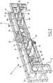
- figure 1 shows a partly cut-away side view of a
sorting apparatus according to the invention;
- figure 2 is a schematic perspective view of a part
of the sorting apparatus along the arrow II in figure 1;
- figure 3 shows a partly sectional top view of a part
of the apparatus along the arrow III in figure 1;
- figure 4 is a schematically extended top view of the
transporting elements of the sorting apparatus;
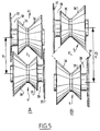
- figure 5 shows in schematic top view the increase in
the distance between two successive transporting elements;
- figure 6 is a partly cut-away perspective view of
the mechanism for adjusting the sorting size of the
sorting apparatus;
- figure 7 shows a second embodiment of the diaboloshaped
transporting elements;
- figures 8A and 8B show views of the segments of the
diabolo-shaped transporting elements in disassembled
situation; and
- figure 9 is a perspective view of a second embodiment
of the sorting apparatus.
-
-
A sorting apparatus 1 (figure 1) comprises means 2
for transport at an angle to the direction of fall or the
vertical of products (not shown here) which must be
sorted to size. Transporting means 2, which are adapted
for uniformly supported transport of the products, have
openings 3 which are movable in transporting direction T
and the dimensions of which moreover increase in transporting
direction T. The openings are herein formed
between transporting elements 4 by which the products are
supported during transport. These transporting elements 4
are movable relative to each other as seen in transporting
direction T whereby the dimensions of the openings 3
formed therebetween can be varied. Transporting elements
4 are further rotatable and take the form of a body of
revolution, in the shown example a diabolo shape. Owing
to this shape two successive transporting elements 4
define in each case a regularly formed opening 3 which in
the shown example is practically square.
-
In order to vary the mutual distance between successive
transporting elements 4 the shafts 5 of transporting
elements 4 are connected to the outer ends of pivot arms
6 respectively 7, the other ends of which are connected
to a drive chain 10. Shafts 5 of transporting elements 4
are herein further provided with guide elements, in the
shown embodiment guide rollers 11 respectively 12, with
which they are carried along an associated guide track 8
respectively 9. The distance between these guide tracks
8, 9 and the path described by drive chain 10 increases
as seen in the transporting direction since one of the
guide tracks 8 is displaced stepwise upward and the other
guide track 9 is displaced stepwise downward. The upper
pivot arms 6 hereby pivot increasingly further upward,
while lower pivot arms 7 are pivoted increasingly further
downward. The space between the successive transporting
elements 4, i.e. the centre-to-centre distance d between
the rotation shafts 5 thereof, therefore becomes increasingly
larger as seen in the transporting direction T, so
that increasingly larger sorting openings 3 are thus
formed. This is shown clearly in figure 4 which in fact
shows a plan view of the spaces actually running in a
zigzag between successive rows of transporting elements
4.
-
As stated, the drive of pivot arms 6, 7 and thereby
of shafts 5 with the rows of transporting elements 4
arranged thereon takes place by means of a chain 10. This
chain is trained over two chain wheels (not shown here)
which are mounted for rotation round respective shafts 71
and 72 in frame 17 of sorting apparatus 1. The chain
wheel mounted on shaft 71 is herein driven via a drive
chain 15 by a motor 16 fixed onto frame 17.
-
Mounted coaxially with the chain wheels on shafts
71, 72 are reversing rollers 13, 14 over which the guide
rollers of shafts 5 with the transporting elements 4 are
guided at the transition from the transport part to the
return part of the apparatus and vice versa. In the
return part of the apparatus two separate guide tracks 23
are herein provided along which guide rollers 24 of
shafts 5 can run. Guide rollers 11 and 12 are herein held
clear of this return track 23, whereby they wear less.
Because return rollers 24 moreover have a considerably
larger diameter than the rollers 11, 12 operating in the
transport part, shafts 5 with transporting elements 4
thereon will rotate less rapidly in the return part than
in the transport part, which increases the lifespan of
the associated bearings. The return rollers of relatively
large diameter moreover function as guard, whereby dirt
and dust from the products for sorting is prevented from
reaching the various rotating and moving components of
the apparatus.
-
Each shaft 5 supports a row of diabolo-shaped transporting
elements 4. These transporting elements 4 are
mounted non-rotatably on shaft 5, for instance in that
shaft 5 and the associated central opening in transporting
elements 4 have a non-round, in the shown embodiment
hexagonal, cross-section (figure 3). Shaft 5 is received
at both its ends in a sleeve 27 and fixed therein by
means of fixing elements, in this case socket screws.
Sleeve 27 is provided on its side remote from transporting
elements 4 with two bearings 29 arranged therein
whereby sleeve 27 and therewith shaft 5 and transporting
elements 4 are mounted rotatably on a shaft stub 30 which
is fixed to the end of one of the pivot arms 6, 7. The
other end of pivot arms 6, 7 is connected to drive chain
10. Pivot arms 6, 7 are herein pivotable in each case
round a shaft 25 by which two adjoining links 26 of the
drive chain are connected. The form of pivot arms 6, 7 is
chosen such that the successive shafts 5 with transporting
elements 4 do not make mutual contact when the associated
guide tracks 8, 9 move apart. For this purpose the
upper pivot arms 6 are provided with a part 31 directed
at an angle to transporting elements 4, while the lower
pivot arms 7 are embodied in the form of a crank. These
lower arms 7 have a part 32 adjacent to chains 10 and
directed obliquely upward, a transverse connecting part
33 which spans the upper guide track 8 and a part 34
directed obliquely downward which connects transverse
part 33 to shaft stub 30. Due to this configuration each
pivot arm 6, 7 is in all circumstances held clear of the
other pivot arm and the shaft with transporting elements
connected thereto.
-
As stated, regularly formed, in particular square
openings 3 are defined by the choice of diabolo-shaped
transporting elements 4. In order to ensure a wide adjustment
range and herein still retain the main form of
openings 3, the diabolos 3 are embodied asymmetrically.
Each diabolo has a relatively small, frusto-conical part
35 and a similarly shaped larger part 36. Further arranged
herein at some distance from the smaller part 35
is an end disc 37 which together with the smaller part 35
bounds a peripheral groove 38. The diabolos 4 on successive
shafts 5 face in each case in opposing directions so
that the small part 35 of the one diabolo lies opposite
the larger part 36 of the following diabolo. The larger
part 36 of the one diabolo 4 hereby engages as it were in
the groove 38 of the other diabolo 4. Shafts 5 can thus
be moved very closely towards each other without the
diabolo-shaped transporting elements 4 making mutual
contact, wherein, as stated, a square opening 3 is defined
between the diabolos (figure 5). This square shape
is herein retained even when shafts 5 with diabolos 4
thereon are moved further apart, as shown by the dashed
lines in figure 5B.
-
The adjustment range of diabolos 4 can be increased
still further by embodying these in the form of a number
of separate segments 35, 36, 37 and 76 (figure 8A) which
are pushed onto shaft 5 adjacently of each other. In the
shown embodiment an end disc 37 respectively 76 is thus
arranged herein on either side of diabolo 4 whereby a
groove 38 respectively 77 is therefore also defined on
either side. Diabolo 4 can now be enlarged in simple
manner by placing a filler ring 78 between the two frusto-conical
segments 35,36 (figure 8B). In this manner
larger products can thus be sorted by also choosing a
larger distance between successive shafts 5.
-
Another possibility enabling sorting of large products,
and particularly obtaining a large sorting range,
is to place two sorting apparatuses in series 1L and 1S
(figure 9). Sorting apparatus 1L for large products
herein has a first sorting stage 79 where the small
products which must be further sorted to size in the
second sorting apparatus 1S are separated from the larger
products.
-
These small products herein drop onto a short belt
conveyor 80 co-displacing with transporting elements 4
and then fall via a slide track 81 onto a lower-lying
belt conveyor 82 extending under the first sorting apparatus
1L. This belt conveyor 82 carries the small products
to a booster conveyor 83, whereby they are transferred
via a slide track 84 to the beginning of the
second sorting apparatus 1S. Here the products are then
sorted to (stepwise increasing) size in successive sorting
stages 85, 86 and 87 and subsequently discharged via
associated cross conveyors 88, 89 and 90.
-
The larger products which have passed through the
pre-sorting stage 79 are carried in the first sorting
apparatus 1L successively along two further sorting
stages 91 and 92 and sorted to size therein, whereafter
they are discharged by cross conveyors 93 and 94.
-
With a suitable choice of the distance between
shafts 5 and of the dimensions of diabolos 4 both sorting
apparatuses 1L and 1S can be adapted precisely to the
dimensions of the products for sorting.
-
In order enable moving apart of guide tracks 8, 9
and thereby the successive rows of transporting elements
4, the guide tracks 8, 9 are formed by a number of segments
8A-8D and 9A-9D mutually connected by means of
hinges 69, 70. These segments can be displaced in vertical
direction by means of an adjusting mechanism 75
(figure 6), of which the apparatus comprises three in the
shown embodiment. Each adjusting mechanism 75 is operated
by means of a handwheel 40 which is connected to a shaft
45 mounted rotatably in an opening in a cover strip 47 of
frame 17 and a bearing bush 48 received in a cross beam
49 of the frame. Shaft 45 is provided with a threaded
part 46, the purpose of which is explained below. Arranged
on the underside of the shaft is a chain wheel 50
over which a chain 51 is guided. This chain 51 is guided
successively over chain wheels 52, 53R, 54R, 55R 56L,
55L, 54L, 53L and 57 and subsequently led back again to
the chain wheel 50 operated by handwheel 40. Chain wheels
52, 55, 56 and 57 herein function solely as guide wheels,
while chain wheels 53 and 54 are respectively connected
to screw spindles 58 and 59 for adjusting guide tracks 9
and 8. Each screw spindle 58, 59 is herein mounted for
rotation in a longitudinal beam 60, 61 of frame 17 and
has a threaded part 62 respectively 63. Threaded parts
62, 63 are each received in a threaded bush 64, 65, which
bushes 64, 65 are each connected to one of the guide
tracks 9, 8.
-
When handwheel 40 is now turned in the direction
indicated by arrow R1, chain wheel 50 rotates in the
direction of arrow R2, whereby chain 51 is displaced and
herein drives chain wheels 53R, 54R rotatingly in the
respective directions RD and RU. The rotation of chain
wheel 53R in direction RD results in threaded part 62
being rotated further into threaded bush 64R. Because
spindle 58 is fixed in vertical direction, this results
in threaded bush 64R being moved downward in the direction
of arrow D, carrying with it the segment 9A of guide
track 9 connected thereto. The rotation of chain wheel
54R in the direction RU simultaneously results in threaded
part 63 being moved downward in bush 65, which results in
bush 65 moving upward as according to arrow U, carrying
with it the segment 8A of guide track 8. Segments 8A, 9A
of guide tracks 8, 9 are thus moved apart from their rest
position in which they lie level, whereby the openings 3
between the successive rows of transporting elements 4
become larger.
-
The operation of the apparatus is now as follows: A
collection of products for sorting, for instance potatoes,
is tipped onto the conveyor belt 2 of apparatus 1
on the infeed side, in the shown embodiment on the left-hand
side of figure 1 or figure 4. Apparatus 1 is herein
driven by motor 16, whereby the products are transported
in the direction of arrow T. As a result of the rotation
movement of the diabolo-shaped transporting elements the
products are herein turned such that each two successive
transporting elements 4 eventually support a single
product. In principle this product remains lying between
two transporting elements 4 until the opening 3 therebetween
becomes so large that the product drops therethrough.
The product is therefore fully supported up to
the moment that it is selected. The risk of damage to the
product is hereby very small. Because transporting elements
4 continue to move increasingly further apart as
seen in the transporting direction T, it will moreover
never be possible for the product to become lodged between
these transporting elements. No blockage of the
sorting apparatus therefore occurs, so that it will not
have to be stopped for the interim.
-
When, depending on its dimensions, the product
finally drops through opening 3 in stage 18, 19 or 20, it
is guided by inclining walls 22 onto a cross conveyor 41,
42 or 43, by which the thus sorted products are discharged
to respective collecting containers or crates.
Products which have still not been selected after passing
over sorting stage 20 are designated "oversized" and will
generally fall in the last stage 21 through the openings
which at that moment are very large and be discharged by
a cross conveyor 44. Should some products then still not
have fallen through the opening, they will roll off the
transporting elements 4 at the end of the track when they
reach reversing roller 12 and come to lie at the end of
the machine. Because transporting elements 4 are driven
in constant rotation, there is no danger in this case
either of the products becoming lodged between two successive
transporting elements 4.
-
The desired size of the sorted products can easily
be adjusted per stage by rotating the associated hand-wheel
40. A nut 66 arranged on the threaded part 46 of
shaft 45 and provided with a protruding finger 67 arranged
in a slot 68 will then herein be moved up and
downward along threaded part 46, this movement forming a
measure for the adjusted sorting size. A calibration can
be arranged for this purpose along the edge of slot 68,
wherein finger 67 functions as indicating instrument. The
settings could of course also be performed automatically
using electronically controlled adjusting motors.
-
Although the invention is elucidated above with
reference to an embodiment, it will be apparent to the
skilled person that it is not limited thereto and can be
modified in many ways. Only one of the guide tracks 8, 9
would thus need to be height-adjustable to achieve the
desired enlargement of the openings 3 between transporting
elements 4. Other methods can also be envisaged to
increase the distance between successive transporting
elements 4. The shafts 5 with transporting elements 4
could for instance be transferred from a first relatively
slow-running drive chain to a second quicker running
drive chain, whereby the space between successive shafts
with transporting elements would likewise increase By
placing one after the other a number of drive chains
moving at increasing speed a number of successive sorting
stages could thus be formed with increasing openings
between the transporting elements. The scope of the
invention is therefore determined solely by the appended
claims.