EP0951943A2 - Entkupplungsvorrichtung für einen batteriebetriebenen, fahrbaren Gartenzerstäuber - Google Patents
Entkupplungsvorrichtung für einen batteriebetriebenen, fahrbaren Gartenzerstäuber Download PDFInfo
- Publication number
- EP0951943A2 EP0951943A2 EP19990303167 EP99303167A EP0951943A2 EP 0951943 A2 EP0951943 A2 EP 0951943A2 EP 19990303167 EP19990303167 EP 19990303167 EP 99303167 A EP99303167 A EP 99303167A EP 0951943 A2 EP0951943 A2 EP 0951943A2
- Authority
- EP
- European Patent Office
- Prior art keywords
- tank
- pump unit
- pressure relief
- respect
- latch
- Prior art date
- Legal status (The legal status is an assumption and is not a legal conclusion. Google has not performed a legal analysis and makes no representation as to the accuracy of the status listed.)
- Withdrawn
Links
- 230000007246 mechanism Effects 0.000 title claims abstract description 59
- 239000012530 fluid Substances 0.000 claims abstract description 20
- 238000013022 venting Methods 0.000 claims description 12
- 238000005507 spraying Methods 0.000 claims description 2
- 239000007788 liquid Substances 0.000 description 5
- 230000009977 dual effect Effects 0.000 description 2
- 238000000034 method Methods 0.000 description 2
- 238000012986 modification Methods 0.000 description 2
- 230000004048 modification Effects 0.000 description 2
- 230000009467 reduction Effects 0.000 description 2
- 241000833016 Ballus Species 0.000 description 1
- 230000009471 action Effects 0.000 description 1
- 230000000295 complement effect Effects 0.000 description 1
- 238000001816 cooling Methods 0.000 description 1
- 238000006073 displacement reaction Methods 0.000 description 1
- 230000005484 gravity Effects 0.000 description 1
- 230000008569 process Effects 0.000 description 1
- 238000005086 pumping Methods 0.000 description 1
- 239000007921 spray Substances 0.000 description 1
Images


Classifications
-
- B—PERFORMING OPERATIONS; TRANSPORTING
- B05—SPRAYING OR ATOMISING IN GENERAL; APPLYING FLUENT MATERIALS TO SURFACES, IN GENERAL
- B05B—SPRAYING APPARATUS; ATOMISING APPARATUS; NOZZLES
- B05B9/00—Spraying apparatus for discharge of liquids or other fluent material, without essentially mixing with gas or vapour
- B05B9/03—Spraying apparatus for discharge of liquids or other fluent material, without essentially mixing with gas or vapour characterised by means for supplying liquid or other fluent material
- B05B9/04—Spraying apparatus for discharge of liquids or other fluent material, without essentially mixing with gas or vapour characterised by means for supplying liquid or other fluent material with pressurised or compressible container; with pump
- B05B9/08—Apparatus to be carried on or by a person, e.g. of knapsack type
- B05B9/0805—Apparatus to be carried on or by a person, e.g. of knapsack type comprising a pressurised or compressible container for liquid or other fluent material
-
- Y—GENERAL TAGGING OF NEW TECHNOLOGICAL DEVELOPMENTS; GENERAL TAGGING OF CROSS-SECTIONAL TECHNOLOGIES SPANNING OVER SEVERAL SECTIONS OF THE IPC; TECHNICAL SUBJECTS COVERED BY FORMER USPC CROSS-REFERENCE ART COLLECTIONS [XRACs] AND DIGESTS
- Y10—TECHNICAL SUBJECTS COVERED BY FORMER USPC
- Y10T—TECHNICAL SUBJECTS COVERED BY FORMER US CLASSIFICATION
- Y10T137/00—Fluid handling
- Y10T137/598—With repair, tapping, assembly, or disassembly means
- Y10T137/6116—With holding means functioning only during transportation assembly or disassembly
-
- Y—GENERAL TAGGING OF NEW TECHNOLOGICAL DEVELOPMENTS; GENERAL TAGGING OF CROSS-SECTIONAL TECHNOLOGIES SPANNING OVER SEVERAL SECTIONS OF THE IPC; TECHNICAL SUBJECTS COVERED BY FORMER USPC CROSS-REFERENCE ART COLLECTIONS [XRACs] AND DIGESTS
- Y10—TECHNICAL SUBJECTS COVERED BY FORMER USPC
- Y10T—TECHNICAL SUBJECTS COVERED BY FORMER US CLASSIFICATION
- Y10T137/00—Fluid handling
- Y10T137/8593—Systems
- Y10T137/86292—System with plural openings, one a gas vent or access opening
- Y10T137/86324—Tank with gas vent and inlet or outlet
Definitions
- the disclosed invention relates to portable sprayers of pressurized liquids, and in particular to a release mechanism for de-pressurizing a sprayer tank and unlocking the sprayer tank with respect to a pump head.
- Pressurized sprayers of various types are currently available on the market. Generally, the available sprayers suffer from many disadvantages. Most portable sprayers are either limited in capacity or are difficult to maneuver. Furthermore, many currently available sprayers require manual pumping and thus are difficult to use. Various types of sprayers, as described below, are currently known in the art.
- U.S. Patent 4,925,105 to Lin discloses a rechargeable battery powered garden sprayer. The user can hold the sprayer with a strap or handle.
- U.S.Patent 5,014,884 to Wunsch discloses a spray container having a piston or gear pump. The pump is used to pump the fluid out of the container rather than to pressurize the tank.
- U.S. Patent 4,618,099 to Nagao et al. discloses an electric spraying device having a pump and a motor.
- the tank can be carried by its handle.
- U.S. Patent 4,135,669 to Bridges et al. discloses a wheeled sprayer with a pressurized liquid reservoir.
- U.S. Patent 4,651,903 to Pagliai discloses a motorized pump pressurized liquid sprayer.
- a vessel pressurized by the pump is centrally disposed within a container.
- U.S. Patent 5,072,884 to Ellison et al. discloses a garden sprayer having an elliptically shaped wand and a manual pump.
- U.S. Patent 3,901,449 to Bochmann discloses a portable sprayer having a handle and a pump powered by rechargeable batteries.
- U.S Patent 4,787,560 to DeYoreo discloses a portable liquid sprayer with two handles.
- An object of embodiments of the present invention is to provide a mechanism for de-pressurizing a fluid tank prior to disconnecting the fluid tank from a pump unit and for depressurizing a fluid tank automatically when a predefined threshold pressure is reached.
- a further object of embodiments of the present invention is to provide a mechanism for locking and unlocking the connection between a fluid tank and a pump unit.
- a further object of the embodiments of the present invention is to provide a portable sprayer having a mechanism for locking the connection between a fluid tank and a pump unit, and for unlocking the connection and de-pressurizing the fluid tank prior to disconnecting the fluid tank from the pump unit.
- a further object of embodiments of the present invention is to provide a method of disconnecting a fluid tank from a pump unit comprising de-pressurizing the fluid tank before it is disconnected from the pump unit.
- a pressure relief mechanism including a first portion and a second portion, relatively displaceable with respect to one another to open an air passage and allow venting; wherein movement of the first portion relative to the second portion causes pressure relief and substantially simultaneously causes unlocking of the lid; and movement of the second portion relative to the first portion causes venting without unlocking of the lid.
- an apparatus for disconnecting a pump unit from a tank wherein the pump unit and tank are releasably connected and wherein tank pressure is relieved prior to disconnecting the pump unit and the tank.
- the apparatus comprises: a pressure relief mechanism comprising a first portion and a second portion relatively displaceable with respect to one another, wherein when the first portion is moved relative to the second portion, an air passage is opened between the first portion and the second portion to cause pressure relief; a latch operatively connected with the first portion, such that when the first portion is moved relative to the second portion, the latch unlocks the pump unit with respect to the tank such that the pump unit and tank become relatively rotatable simultaneously with pressure relief.
- a pressure relief assembly for preventing a pressurized vessel from exceeding a pre-defined threshold pressure
- the pressure relief assembly comprising: a piston for operating a pressure relief device; a housing having an opening configured to restrict movement of the piston in a first direction and allow movement of the piston in a second direction.
- FIG. 1 A block diagram illustrating an exemplary computing environment in accordance with the present invention.
- FIG. 1 A block diagram illustrating an exemplary computing environment in accordance with the present invention.
- FIG. 1 A block diagram illustrating an exemplary computing environment in accordance with the present invention.
- FIG. 1 A block diagram illustrating an exemplary computing environment in accordance with the present invention.
- FIG. 1 A block diagram illustrating an exemplary computing environment in accordance with the present invention.
- a pump unit is disconnected from a fluid tank by displacing a mechanism relative to the pump unit thereby de-pressurizing the tank and unlocking the pump unit for relative rotation with respect to the tank; rotating the pump unit relative to the tank; and disengaging the pump unit from the tank.
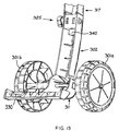
- Fig. 1 is a perspective view of the sprayer assembly.
- Tank 100 is mounted on frame 300.
- Head 200 is secured to tank 100.
- Fig. 2-7 show additional views of the sprayer assembly.
- Tank 100 as shown in Fig. 8 has a curved front wall 101. On top of front wall 101 is an externally threaded inlet 103. On the side of tank 100 is externally threaded outlet 102. Locking projections 104a and 104b are provided at the top of the tank for locking the frame to the tank. On the bottom portion of tank 100, a supporting surface 106 is shaped to be disposed adjacent the frame 300 (not shown in Fig. 8). An engaging surface 105 includes tabs 105a and 105b that are provided for engagement with the frame 300.
- Fig. 9 is a side elevation of tank 100, which additionally shows wheel well 111b within sidewall 110b.
- Fig. 10 is a rear elevation of the tank that shows both wheel wells 111a and 111b. The wheel wells extend forward from rear wall 120.
- Fig.11 is a top plan view of the tank that shows the outline of tank 100.
- the tank has four sidewalls 101, 110a 110b, and 120 and each wall is of a curved configuration.
- the walls of tank 100 are formed such that a safe failure mode is provided for the tank.
- the thickness of the walls is varied such that the walls are thinnest at the top of the tank.
- the thinner wall portions are formed at the top of the tank, under a connecting portion of the frameshown in Fig. 14. Accordingly if failure occurs, no leakage will occur from the bottom of the tank. Further, the provision of a safe failure mode allows most portions of the tank to be thinner than would otherwise be required.
- Fig. 12 is an exploded perspective view of frame 300. Wheels 301a and 301b are connected by axle 310.Apertures 312a and 312b receive axle 310, as is more clearly shown in Fig. 13. Supporting portion 311 extends below axle 310 (in the position shown in Fig. 12), and shaft portion 302 extends upward from supporting portion 311 and connects with upper arm 317.
- An interlocking connection between shaft 302 and upper arm 317 is accomplished by inserting connecting portion 319 of upper arm 317 into shaft 302 such that ribs 316 of the upper arm engage ribs 315 on shaft 302. Ribs 315 are located on both sides of shaft 302 and ribs 316 are located on both sides of upper arm 317.
- the connection forms interlocking joint 325 which is then secured by inserting connectors 313a and 313b (e.g. a bolt and nut) through apertures 314a and 314b in the shaft and apertures 318 in the upper arm.
- Loosening connectors 313a and 313b allows the assembly a limited degree of relative displacement between shaft 302 and upper arm 317 such that frame 300 can be manipulated for easy replacement of the tank 100. Tightening the connectors 313a and 313b interlocks ribs 315 and 316 to secure frame sections 302 and 317 together, thereby securely retaining the tank 100 with respect to the frame 300.
- support portion 311 comprises an extension rib 330 that acts as an outrigger and provides an anti-tip feature.
- rib extension 330 of support arm 311 will touch the ground widening the sprayer's footprint, and ensuring that the sprayer's center of gravity is contained within the boundaries of the footprint.
- Fig. 13 further shows the lower portion of an elongated tube 340 integrated into joint 325 and functioning as a handle.
- the entire configuration of the handle is shown in Fig. 1. With connectors 313a and 313b removed, tube 34() can be moved up and down to adjust the height of the handle.
- the connection between the lower portion of tank 100 and frame 300 is best understood referring to Figs. 2, 10 and 12.
- the tank 100 is secured to the support portion 311 by tabs 105a and 105b near the bottom of the tank 100.
- the tabs 105a and 105b interlock within support arms 331 and 332 on the frame 300.
- Tabs 105a and 105b project downwardly and each has a hole roughly in the center of the tab.
- Each support arm 331 and 332 of the frame 300 has a recessed section with a pin. Each recessed section engages with a respective tank tab 105a and 105b, and the pins interlock with the holes in the tank tabs 105a and 105b.
- tank 100 is engaged with frame 300 by tilting the tank 100, engaging tank tabs 105a and 105b with the support arm recess at a 45 degree angle from its normal assembled position, then tilting the tank upright in the normal assembled position. Integral ribs on the frame 300 help guide the tank 100 into position during the assembly process.
- tank 100 is secured to upper arm 317 by key type openings 320a and 320b (see Fig. 12) on upper arm 317 that engage with projections 1 04a and 104b on tank 100.
- a collar 321 of upper arm 317 surrounds inlet 103 of tank 100 at inlet flange 108.
- Projections 104a and 104b are radially aligned on opposite sides of inlet flange collar 108, and each has a notch profile projecting through the key type openings 320a and 320b in the frame. The notches lock into the openings when the frame collar 321 is fully engaged with the corresponding inlet flange 108.
- power head 200 is mounted on top of tank 100. Opening 201 in power head 200 is secured onto inlet 103 of tank 100.
- the power head 200 is designed such that disassembly from the tank 100 does not cause a sudden release of pressure from the tank 100.
- the head 200 is provided with a locking Feature to ensure that once the sprayer is assembled and full pressure is attained, the head 200 must be deliberately unlocked prior to unscrewing and removing. As part of the unlocking action, there is a reduction in tank pressure prior to unscrewing. This reduction in tank pressure also reduces the effort required to unscrew the head 200.
- release mechanism 210 includes slide 212 that retractably projects outside head 200 for interlocking with locking projections 104a projecting upward from tank 100.
- Slide 212 travels vertically within guide 240 in the housing.
- Leading edge 213 of slide 212 is ramped so that when head 200 is rotated into a tightened position, slide 212 will lift up slightly until the head threads are fully engaged with tank 100.
- a slot 214 in the lever section allows slide 212 to drop down on the locking projection 104a of tank 100. This locks the head 200 into position.
- the user must lift slide 212 by extended side projection 215 to disengage slide 212 from locking projection 104a and unscrew head 200 from tank 100.
- release mechanism 210 comprises ribs 218 that support a pressure relief device 220.
- a main body of pressure relief device 220 is held on ribs 218, while a piston portion 221 of pressure relief device 220 is held in the housing by an opening 242 that accommodates reduced diameter portion 224 of piston 221.
- the body of pressure relief device 220 moves with slide 212, while piston 221 is held down by housing portion 241, thereby opening pressure relief device 220 and venting air pressure out through vent pipe 226 and an integral tube (not shown) extending through the bottom of the housing at notch 227.
- Fig. 20 illustrates the battery compartments including alignment ribs 250 for the batteries and battery release 252. Terminal boards 253 are provided near the bottom of alignment ribs 250. Air vents 254 and 258 appear at various locations on the power head. A pressure controller 255 is connected by air line to pump 222. A main switch 256 having a weathcr resistant cover is located on the top of power head 200. Front pump mount 257 is provided for mounting a pump that pressurizes tank 100.
- power head 200 in its interior, is equipped with a pump 222 powered by a motor 224.
- Pump 222 is mounted on front pump mount 257 and rear pump mount 259, and when powered by motor 224, pressurizes the interior of tank 100.
- Pressure controller 255 is actuated when tank pressure gets below a given threshold in order to activate motor 224 and pump 222 to pressurize the interior of tank 100.
- Batteries are provided in the battery compartments for powering motor 224 and pump 222.
- Air vents 254 and 258 provide air inlet and cooling entry within power head 200.
- an integral molded spring 216 biases slide 212 toward tank 100.
- a ramp 213 is located at the base of slide 212 for abutting locking projections 104a on tank 100 as described in connection with Fig. 15.
- Notched portion 214 automatically locks onto locking projection 104a under the influence of spring 216 and pressure relief assembly mounted to slide 212.
- Fig. 23 shows further features of the power head including the guide 240 in the housing.
- a complementary guide (not shown) exists on the opposite side of the slide 212.
- a hose 219 is provided for connecting opening 201 and pressure relief device 220.
- a pressure relief tube 226 is provided for venting upon actuation of slide 212.
- Spigot 231 allows for connecting pressure relief hose 219 within opening 201 of power head 200.
- Spigot 241 provides a connection for a hose (not shown) from pump 222.
- Pump 222 is preferably a piston pump, but may be of any configuration capable of functioning within power head 200.
- Figs. 24 through 29 more clearly illustrate the details of pressure relief mechanism 220.
- the mechanism serves a dual function when incorporated in the pump/tank environment. As already explained in detail with reference to Figs. 15 and 20 through 23, the mechanism functions in conjunction with lever 215 and slide 212to relieve pressure while unlocking head 200. Additionally, pressure relief mechanism 220 will automatically cause venting when the pressure in the tank reaches a predetermined threshold pressure. The over-pressurized condition causes piston 221 to move downwardly, thereby creating an air passageway such that venting can occur through tube 226. As shown in Fig. 23 and more clearly shown in Fig. 24, reduced diameter portion 224 of piston 221 can freely move downwardly within the opening 242 in the housing 241. However, because of enlarged diameter portion 225 of piston 221, the piston cannot move upwardly within opening 242.
- the pressure relief mechanism includes two moveable portions.
- a first or main body portion 250 of the pressure relief mechanism 220 is caused to move upwardly. This upward movement creates an air passageway such that venting occurs through tube 226.
- piston 221, or the second portion of the pressure relief mechanism 220 is forced downwardly, thereby creating an air passageway to allow venting through tube 226.
- the pressure relief mechanism is able to perform this dual function.
- Figs. 28(A) and 28(b) isolate the pressure relief mechanism.
- Upper housing 250a and lower housing 250b form the complete housing 250.
- Ribs 218 of the release mechanism engage body 250 at engagement portion 260 (See 28(a)).
- lever 215 is lifted, the entire body portion 250 is also lifted, while piston 221 remains stationary.
- Fig. 29 is an exploded view of the pressure relief mechanism that shows upper housing 250a and lower housing 250b encapsulating piston 221.
- O-ring 262 is positioned on the upper portion of piston 221 and a spring 264 biases piston 221 in position.
- a simple and effective hose to tank connection is provided for transporting fluid between tank 100 and an outlet hose.
- the outlet hose to tank connection utilizes externally threaded outlet 102 of tank 100.
- a flexible hose 401 is connected through cap 402 to tank 100.
- Hose 401 extends around siphon tube 405.
- a gasket 406 is disposed adjacent the lip of threaded outlet 102, surface 403 of cap 402, and hose 401. Threaded outlet 102 of tank 100 and cap 402 exert a compressive force on gasket 406, thereby causing hose 401 to be flared out at its lower end and held open.
- Fig. 31 shows an alternative configuration for the shape of gasket 406 and cap 402.
Landscapes
- Catching Or Destruction (AREA)
- Filling Or Discharging Of Gas Storage Vessels (AREA)
- Details Of Reciprocating Pumps (AREA)
- Details Or Accessories Of Spraying Plant Or Apparatus (AREA)
Applications Claiming Priority (2)
| Application Number | Priority Date | Filing Date | Title |
|---|---|---|---|
| US66203 | 1998-04-24 | ||
| US09/066,203 US6125879A (en) | 1997-08-20 | 1998-04-24 | Release mechanism for a battery powered wheeled garden sprayer |
Publications (2)
| Publication Number | Publication Date |
|---|---|
| EP0951943A2 true EP0951943A2 (de) | 1999-10-27 |
| EP0951943A3 EP0951943A3 (de) | 2001-05-02 |
Family
ID=22067941
Family Applications (1)
| Application Number | Title | Priority Date | Filing Date |
|---|---|---|---|
| EP19990303167 Withdrawn EP0951943A3 (de) | 1998-04-24 | 1999-04-23 | Entkupplungsvorrichtung für einen batteriebetriebenen, fahrbaren Gartenzerstäuber |
Country Status (4)
| Country | Link |
|---|---|
| US (1) | US6125879A (de) |
| EP (1) | EP0951943A3 (de) |
| JP (1) | JPH11342355A (de) |
| AU (1) | AU2369699A (de) |
Families Citing this family (4)
| Publication number | Priority date | Publication date | Assignee | Title |
|---|---|---|---|---|
| US7556210B2 (en) * | 2006-05-11 | 2009-07-07 | S. C. Johnson & Son, Inc. | Self-contained multi-sprayer |
| US8985482B1 (en) * | 2007-11-09 | 2015-03-24 | Fore front Product Design, LLC | Portable pressurized sprayer |
| FR3028190B1 (fr) * | 2014-11-12 | 2021-02-19 | Frank Labbe | Pulverisateur portable autonome electrique |
| CN212943592U (zh) | 2017-07-27 | 2021-04-13 | 米沃奇电动工具公司 | 动力液体喷雾器 |
Citations (10)
| Publication number | Priority date | Publication date | Assignee | Title |
|---|---|---|---|---|
| US3901449A (en) | 1974-03-01 | 1975-08-26 | Hudson Mfg Co H D | Cordless electric sprayer |
| US4135669A (en) | 1977-08-30 | 1979-01-23 | Bridges Edward B | Portable, wheeled electric sprayer with pressurized liquid reservoir |
| US4618099A (en) | 1984-07-13 | 1986-10-21 | Kyushu Hitachi Maxell, Ltd. | Electric spray |
| US4651903A (en) | 1986-04-21 | 1987-03-24 | Pagliai Ferro D | Motorized pump pressurized liquid sprayer |
| US4787560A (en) | 1985-12-04 | 1988-11-29 | Blue Mountain Products Inc. | Portable liquid sprayer |
| US4881687A (en) | 1987-06-29 | 1989-11-21 | Tecnoma | Portable liquid sprayer, particularly for the treatment of plants |
| US4925105A (en) | 1989-04-14 | 1990-05-15 | Lin Hsien C | Rechargeable garden sprayer |
| US5014884A (en) | 1988-10-25 | 1991-05-14 | Erich Wunsch | Spray container |
| US5072884A (en) | 1989-08-11 | 1991-12-17 | Root-Lowell Corporation | Elliptical tank portable garden sprayer |
| US5150837A (en) | 1989-07-28 | 1992-09-29 | Alberto Ferrari | Backpack spraying equipment |
Family Cites Families (77)
| Publication number | Priority date | Publication date | Assignee | Title |
|---|---|---|---|---|
| CA656686A (en) * | 1963-01-29 | H. Pinke August | Spraying apparatus | |
| US929597A (en) * | 1909-02-18 | 1909-07-27 | Adolph Johnson | Tennis-court marker. |
| US982140A (en) * | 1909-12-02 | 1911-01-17 | Keighley Company | Lasting apparatus. |
| US1277269A (en) * | 1915-05-14 | 1918-08-27 | Herman Edward Sturcke | Spraying or atomizing system. |
| US1714296A (en) * | 1927-08-06 | 1929-05-21 | Erie Meter Systems Inc | Dispensing-tank mechanism |
| US2086969A (en) * | 1936-03-26 | 1937-07-13 | Hell Co | Vent assemblage |
| US2227222A (en) * | 1939-12-01 | 1940-12-31 | Henderson James Roy | Plant spraying apparatus |
| US2385514A (en) * | 1944-02-07 | 1945-09-25 | Roe C Hawkins | Barrel truck |
| US2529645A (en) * | 1945-06-13 | 1950-11-14 | Lowell Specialty Company | Spraying apparatus |
| US2544651A (en) * | 1945-09-17 | 1951-03-13 | Chicago Bridge & Iron Co | Method of storing volatile liquids |
| US2465554A (en) * | 1946-10-21 | 1949-03-29 | Roy Maurice | Portable electric air pump |
| US2493599A (en) * | 1947-06-10 | 1950-01-03 | Walter J Schroeder | Single-row fertilizer applicator |
| US2629539A (en) * | 1947-12-30 | 1953-02-24 | Payswell Products Corp | Motor-driven compressor unit |
| US2853212A (en) * | 1955-10-14 | 1958-09-23 | Hudson Mfg Co H D | Compression sprayer |
| US2953387A (en) * | 1959-06-15 | 1960-09-20 | David Lehrman | Supporting device |
| US3050260A (en) * | 1960-12-12 | 1962-08-21 | City Parking Ltd | Spray gun carriers |
| US3173584A (en) * | 1962-11-15 | 1965-03-16 | Steve T Giavasis | Portable motor driven dispensing devices |
| US3608832A (en) * | 1969-09-04 | 1971-09-28 | Energy Sciences Inc | Spray nozzle assembly operable at low pressure |
| DE2055868A1 (de) * | 1970-11-13 | 1972-05-18 | Fuss, Willi, 6800 Mannheim | Tragbares Sprühgerät |
| BE795588A (fr) * | 1972-02-16 | 1973-06-18 | O M Scott & Sons Cy | Epandeur de matieres avec reservoir enfichable |
| US3797743A (en) * | 1973-07-26 | 1974-03-19 | Broyhill Co | Utility sprayer unit |
| US3894816A (en) * | 1973-08-22 | 1975-07-15 | Wooster Brush Co | Hand held paint sprayer |
| JPS5227033Y2 (de) * | 1974-05-20 | 1977-06-20 | ||
| US3915351A (en) * | 1974-08-19 | 1975-10-28 | Alexander Enrico Kiralfy | Cordless electrically operated centrifugal pump |
| US3977602A (en) * | 1974-10-29 | 1976-08-31 | Kirch Paul W | Mobile spray apparatus |
| US3940843A (en) * | 1974-12-16 | 1976-03-02 | R. E. Chapin Manufacturing Works, Inc. | Method of forming an extension tube assembly |
| US4080105A (en) * | 1975-07-14 | 1978-03-21 | Connell Edwin E | Tire inflator |
| US3963178A (en) * | 1975-09-08 | 1976-06-15 | Root-Lowell Manufacturing Co. | Sprayer nozzle |
| US4034916A (en) * | 1975-12-12 | 1977-07-12 | Helene Curtis Industries, Inc. | Single station spray system |
| US4166579A (en) * | 1976-09-07 | 1979-09-04 | Stewart-Warner Corporation | Paint sprayer safety interlock |
| US4104744A (en) * | 1977-02-15 | 1978-08-08 | Clyde Odencrantz | Washing device |
| US4154401A (en) * | 1977-11-21 | 1979-05-15 | Thompson William E | Spray unit and pressurizing adapter therefor |
| US4269356A (en) * | 1978-12-21 | 1981-05-26 | Rose Donald D | Portable agricultural sprayer |
| US4301971A (en) * | 1979-08-23 | 1981-11-24 | Cornelius Engineering Center, Inc. | Electrically-driven spray gun |
| ATE17988T1 (de) * | 1981-08-01 | 1986-03-15 | Walkover Ltd | Spritzgeraete. |
| FR2545006B1 (fr) * | 1983-04-27 | 1985-08-16 | Mancel Patrick | Dispositif pour pulveriser des produits, notamment des peintures |
| MX157782A (es) * | 1983-06-06 | 1988-12-14 | Pedro Wurtz Luchsinger | Mejoras en bomba agricola aspersora manual de diafragma |
| DE3400356A1 (de) * | 1984-01-07 | 1985-07-18 | Heinrich Baumgarten KG, Spezialfabrik für Beschlagteile, 5908 Neunkirchen | Dampfdruckkochtopf |
| US4717074A (en) * | 1984-06-25 | 1988-01-05 | Wagner Spray Tech Corporation | Adjustable orifice for a sprayer unit |
| GB2164533B (en) * | 1984-09-22 | 1987-10-07 | Walkover Ltd | Applicator |
| JPS61165826A (ja) * | 1985-01-16 | 1986-07-26 | Sanyo Electric Co Ltd | フオ−カスサ−ボ引込回路 |
| US4621984A (en) * | 1985-04-17 | 1986-11-11 | Air Shot, Inc. | Portable air pump |
| CA1282018C (en) * | 1985-04-17 | 1991-03-26 | Akiho Ota | Biaxial-orientation blow-molded bottle-shaped container |
| JP2603065B2 (ja) * | 1985-08-20 | 1997-04-23 | 沖電気工業 株式会社 | 予測フイルタ |
| US4712983A (en) * | 1985-11-08 | 1987-12-15 | Moynihan Patrick B | Air compressor accessory driven by portable electric drill |
| US4725004A (en) * | 1986-08-04 | 1988-02-16 | Baran Jr Walter | Portable spray unit |
| US4782982A (en) * | 1987-01-15 | 1988-11-08 | Root-Lowell Manufacturing Company | Self-pressurizing sprayer |
| US4930664A (en) * | 1987-01-15 | 1990-06-05 | Root-Lowell Manufacturing Company | Self-pressurizing sprayer |
| US4776766A (en) * | 1987-08-14 | 1988-10-11 | Interdynamics, Inc. | Portable air pump assembly and detechable safety lamp for automotive vehicle |
| US4865255A (en) * | 1987-12-03 | 1989-09-12 | Luvisotto Roy G | Self-contained, mobile spraying apparatus |
| DE3812935A1 (de) * | 1988-04-19 | 1989-11-02 | Oeco Tech Entwicklung & Vertri | Automatische spruehdose |
| US4971498A (en) * | 1988-04-22 | 1990-11-20 | R. L. Industries | Cantilevered washer for a fastener |
| US5248089A (en) * | 1988-08-15 | 1993-09-28 | Wagner Spray Tech Corporation | Combination carrying case/paint container |
| US5320859A (en) * | 1988-09-02 | 1994-06-14 | Bahram Namdari | High protein dough mix |
| US4913345A (en) * | 1988-12-14 | 1990-04-03 | Setter Triple S Ltd. | High pressure washer/field spot sprayer |
| US5029758A (en) * | 1989-07-06 | 1991-07-09 | Chayer Steven A | High-efficiency, portable car washing system |
| US4984742A (en) * | 1989-08-11 | 1991-01-15 | Root-Lowell | Container and pump assembly |
| US5033520A (en) * | 1989-09-06 | 1991-07-23 | Manfred Kuehmichel | Refuse disposal container |
| US5154317A (en) * | 1990-07-09 | 1992-10-13 | Roppolo Iii Michael A | Portable liquid dispenser |
| US5119993A (en) * | 1990-10-29 | 1992-06-09 | S. C. Johnson & Son, Inc. | Portable particulate material spreader |
| US5127808A (en) * | 1991-01-14 | 1992-07-07 | Alan Nichols | Portable air pump |
| DE4108775A1 (de) * | 1991-03-18 | 1992-09-24 | Kaercher Gmbh & Co Alfred | Hochdruckreinigungsgeraet |
| US5064170A (en) * | 1991-05-14 | 1991-11-12 | Root-Lowell Corporation | Sprayer shutoff valve |
| US5301877A (en) * | 1992-03-26 | 1994-04-12 | R L Corporation | Lawn and garden sprayer with press-fit nozzle construction |
| DE4305474C2 (de) * | 1993-02-23 | 1997-07-10 | Wei Chien Enterprise Co Ltd | Tragbare Vorrichtung zur Ölentnahme und zum Reifenfüllen bei Fahrzeugen |
| DK168644B1 (da) * | 1993-03-09 | 1994-05-09 | Peter Egelund Soerensen | B rbar, batteridrevet luftpumpe |
| EP0663242A1 (de) * | 1993-06-29 | 1995-07-19 | Atenals, S.L., | Sprühvorrichtung |
| US5415353A (en) * | 1993-08-12 | 1995-05-16 | Rl Corporation | Press-fit handle assembly |
| US5307995A (en) * | 1993-08-12 | 1994-05-03 | Rl Corporation | Lawn and garden sprayer with hose compression connector |
| US5494191A (en) * | 1994-05-02 | 1996-02-27 | Core Incorporated | Fluid containing and dispensing system |
| US5509577A (en) * | 1994-05-02 | 1996-04-23 | Core Incorporated | Fluid storage and dispensing system |
| US5399072A (en) * | 1994-09-29 | 1995-03-21 | Westphal; Timothy D. | Electrical portable air compressor |
| US5553780A (en) * | 1995-02-03 | 1996-09-10 | The Toro Company | Spraying system with low liquid level warning |
| US5636791A (en) * | 1995-07-07 | 1997-06-10 | Gilmour, Inc. | Backpack sprayer |
| US5695121A (en) * | 1995-12-11 | 1997-12-09 | Stillions, Jr.; Richard Harlan | Self contained portable sprayer system |
| US5723710A (en) * | 1996-07-12 | 1998-03-03 | Uop | Zeolite beta and its use in aromatic alkylation |
| US5931207A (en) * | 1997-03-05 | 1999-08-03 | Gianino; Rosario N. | Portable home and garden sprayer, power unit |
-
1998
- 1998-04-24 US US09/066,203 patent/US6125879A/en not_active Expired - Fee Related
-
1999
- 1999-04-09 AU AU23696/99A patent/AU2369699A/en not_active Abandoned
- 1999-04-23 EP EP19990303167 patent/EP0951943A3/de not_active Withdrawn
- 1999-04-23 JP JP11700799A patent/JPH11342355A/ja not_active Withdrawn
Patent Citations (10)
| Publication number | Priority date | Publication date | Assignee | Title |
|---|---|---|---|---|
| US3901449A (en) | 1974-03-01 | 1975-08-26 | Hudson Mfg Co H D | Cordless electric sprayer |
| US4135669A (en) | 1977-08-30 | 1979-01-23 | Bridges Edward B | Portable, wheeled electric sprayer with pressurized liquid reservoir |
| US4618099A (en) | 1984-07-13 | 1986-10-21 | Kyushu Hitachi Maxell, Ltd. | Electric spray |
| US4787560A (en) | 1985-12-04 | 1988-11-29 | Blue Mountain Products Inc. | Portable liquid sprayer |
| US4651903A (en) | 1986-04-21 | 1987-03-24 | Pagliai Ferro D | Motorized pump pressurized liquid sprayer |
| US4881687A (en) | 1987-06-29 | 1989-11-21 | Tecnoma | Portable liquid sprayer, particularly for the treatment of plants |
| US5014884A (en) | 1988-10-25 | 1991-05-14 | Erich Wunsch | Spray container |
| US4925105A (en) | 1989-04-14 | 1990-05-15 | Lin Hsien C | Rechargeable garden sprayer |
| US5150837A (en) | 1989-07-28 | 1992-09-29 | Alberto Ferrari | Backpack spraying equipment |
| US5072884A (en) | 1989-08-11 | 1991-12-17 | Root-Lowell Corporation | Elliptical tank portable garden sprayer |
Also Published As
| Publication number | Publication date |
|---|---|
| AU2369699A (en) | 1999-11-04 |
| JPH11342355A (ja) | 1999-12-14 |
| US6125879A (en) | 2000-10-03 |
| EP0951943A3 (de) | 2001-05-02 |
Similar Documents
| Publication | Publication Date | Title |
|---|---|---|
| US6145711A (en) | Portable sprayer with power pump | |
| CA2113538C (en) | Rim seal for vacuum cleaner having dual storage tanks | |
| JP2634166B2 (ja) | リクレーション用車両 | |
| US7413414B2 (en) | Air compressor assembly | |
| US20020108204A1 (en) | Self-evacuating vacuum cleaner | |
| EP1872657A1 (de) | Tragbare landwirtschaftliche spritzvorrichtung | |
| CA2269392C (en) | Wet/dry vacuum with snap-action powerhead latch | |
| US6923627B1 (en) | Air compressor with extensible handle bar assembly | |
| KR20100112650A (ko) | 유체 저장 및 분배 시스템과 프로세스 | |
| US20080292481A1 (en) | Mastic pump | |
| US6390156B1 (en) | Method and system for transfer of fluid and dry materials from an inverted holding container to a paired docking station receptacle | |
| US4574988A (en) | Pressure vessel for receiving liquids | |
| US6125879A (en) | Release mechanism for a battery powered wheeled garden sprayer | |
| US20240001384A1 (en) | Backpack sprayer | |
| CA2347889C (en) | Outlet priming self-evacuating vacuum cleaner | |
| US20030025002A1 (en) | Pressurizable fluid spray system | |
| US5573135A (en) | Portable liquid tank with manhole cover, liquid mixer and universal pressure relief bung | |
| CN217676667U (zh) | 手持式电动升降机 | |
| EP0894467B1 (de) | Sauggerät mit Pumpe zum Entfernen von Flüssigkeit | |
| KR200299348Y1 (ko) | 진공 청소기 | |
| JPH0243326Y2 (de) | ||
| GB2088955A (en) | Hydraulic Lifting Jack | |
| EP1736252B1 (de) | Tragbare Vorrichtung zum Waschen und Duschen | |
| JPH075791Y2 (ja) | 液体容器 | |
| CA2219682C (en) | Self-evacuating vacuum cleaner |
Legal Events
| Date | Code | Title | Description |
|---|---|---|---|
| PUAI | Public reference made under article 153(3) epc to a published international application that has entered the european phase |
Free format text: ORIGINAL CODE: 0009012 |
|
| 17P | Request for examination filed |
Effective date: 19990508 |
|
| AK | Designated contracting states |
Kind code of ref document: A2 Designated state(s): DE FR GB IT |
|
| AX | Request for extension of the european patent |
Free format text: AL;LT;LV;MK;RO;SI |
|
| PUAL | Search report despatched |
Free format text: ORIGINAL CODE: 0009013 |
|
| AK | Designated contracting states |
Kind code of ref document: A3 Designated state(s): AT BE CH CY DE DK ES FI FR GB GR IE IT LI LU MC NL PT SE |
|
| AX | Request for extension of the european patent |
Free format text: AL;LT;LV;MK;RO;SI |
|
| RIC1 | Information provided on ipc code assigned before grant |
Free format text: 7B 05B 9/08 A, 7F 16K 17/04 B |
|
| 17Q | First examination report despatched |
Effective date: 20010528 |
|
| AKX | Designation fees paid |
Free format text: DE FR GB IT |
|
| GRAH | Despatch of communication of intention to grant a patent |
Free format text: ORIGINAL CODE: EPIDOS IGRA |
|
| STAA | Information on the status of an ep patent application or granted ep patent |
Free format text: STATUS: THE APPLICATION IS DEEMED TO BE WITHDRAWN |
|
| 18D | Application deemed to be withdrawn |
Effective date: 20030927 |