EP0951147B1 - Empfänger und ein Verfahren zür Abstimmung von einer der Hoghfrequenzstufen in einem Empfänger - Google Patents
Empfänger und ein Verfahren zür Abstimmung von einer der Hoghfrequenzstufen in einem Empfänger Download PDFInfo
- Publication number
- EP0951147B1 EP0951147B1 EP99201099A EP99201099A EP0951147B1 EP 0951147 B1 EP0951147 B1 EP 0951147B1 EP 99201099 A EP99201099 A EP 99201099A EP 99201099 A EP99201099 A EP 99201099A EP 0951147 B1 EP0951147 B1 EP 0951147B1
- Authority
- EP
- European Patent Office
- Prior art keywords
- selective
- circuit
- reactive
- level
- receiver
- Prior art date
- Legal status (The legal status is an assumption and is not a legal conclusion. Google has not performed a legal analysis and makes no representation as to the accuracy of the status listed.)
- Expired - Lifetime
Links
Images

Classifications
-
- H—ELECTRICITY
- H04—ELECTRIC COMMUNICATION TECHNIQUE
- H04B—TRANSMISSION
- H04B1/00—Details of transmission systems, not covered by a single one of groups H04B3/00 - H04B13/00; Details of transmission systems not characterised by the medium used for transmission
- H04B1/06—Receivers
- H04B1/16—Circuits
- H04B1/18—Input circuits, e.g. for coupling to an antenna or a transmission line
-
- E—FIXED CONSTRUCTIONS
- E01—CONSTRUCTION OF ROADS, RAILWAYS, OR BRIDGES
- E01F—ADDITIONAL WORK, SUCH AS EQUIPPING ROADS OR THE CONSTRUCTION OF PLATFORMS, HELICOPTER LANDING STAGES, SIGNS, SNOW FENCES, OR THE LIKE
- E01F9/00—Arrangement of road signs or traffic signals; Arrangements for enforcing caution
- E01F9/60—Upright bodies, e.g. marker posts or bollards; Supports for road signs
- E01F9/604—Upright bodies, e.g. marker posts or bollards; Supports for road signs specially adapted for particular signalling purposes, e.g. for indicating curves, road works or pedestrian crossings
- E01F9/608—Upright bodies, e.g. marker posts or bollards; Supports for road signs specially adapted for particular signalling purposes, e.g. for indicating curves, road works or pedestrian crossings for guiding, warning or controlling traffic, e.g. delineator posts or milestones
- E01F9/61—Special features of delineator posts, e.g. with parts cantilevered toward the roadway or fixed vertically on a tilted surface
-
- E—FIXED CONSTRUCTIONS
- E01—CONSTRUCTION OF ROADS, RAILWAYS, OR BRIDGES
- E01F—ADDITIONAL WORK, SUCH AS EQUIPPING ROADS OR THE CONSTRUCTION OF PLATFORMS, HELICOPTER LANDING STAGES, SIGNS, SNOW FENCES, OR THE LIKE
- E01F9/00—Arrangement of road signs or traffic signals; Arrangements for enforcing caution
- E01F9/60—Upright bodies, e.g. marker posts or bollards; Supports for road signs
- E01F9/658—Upright bodies, e.g. marker posts or bollards; Supports for road signs characterised by means for fixing
- E01F9/673—Upright bodies, e.g. marker posts or bollards; Supports for road signs characterised by means for fixing for holding sign posts or the like
- E01F9/677—Upright bodies, e.g. marker posts or bollards; Supports for road signs characterised by means for fixing for holding sign posts or the like the sign posts being removable without tools, e.g. of stud-and-socket type
-
- H—ELECTRICITY
- H03—ELECTRONIC CIRCUITRY
- H03J—TUNING RESONANT CIRCUITS; SELECTING RESONANT CIRCUITS
- H03J2200/00—Indexing scheme relating to tuning resonant circuits and selecting resonant circuits
- H03J2200/10—Tuning of a resonator by means of digitally controlled capacitor bank
Definitions
- the invention also relates to a method for adjusting one of the high frequency amplifier stages contained in such an apparatus.
- EP-A 0 546 723 also describes a selective circuit tunable by a control variable. The setting of this circuit is made during the operation of the device to which it is attached. We do not face the problem of setting the devices at the end of manufacture.
- the present invention provides an apparatus of the type mentioned in the preamble in which there are provided means for facilitating the tuning of the selective stage without using a particular temperature meter and means for maintaining the dynamic voltage applicable to the voltage agree if the selective circuit requires some dynamics in the tuning of its selective circuit.
- One of the ideas of the invention is to insert in the selective circuit one or more reactive elements that allow to center this selective circuit on the frequency range on which the device is supposed to operate.
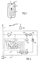
- FIG. 1 there is shown an electronic device according to the invention.
- a wireless telephone device of the CT0 type or others is composed of a microphone 5, an earphone 6, a screen 8, a keyboard 9 and an antenna 11.
- This device is connected to its base, not shown in the figure, using a frequency channel. It should be noted that the invention can also be applied to the base itself.
- FIG. 2 shows on one side the transmission part 40, which is not detailed because it is not part of the invention and the reception part 45. It is in this reception part that the selective amplifier is located which is the high frequency preamplifier .
- This amplifier is shown schematically in this figure by an amplifier 50, proper, at the output of which a selective circuit 51 of the plug circuit type is provided.
- This plug circuit is formed by a self-induction coil 55 at the ends of which is connected a main capacitor 65 which fixes as a first approximation the tuning frequency of this plug circuit.
- This capacitor can also be a diode with variable capacity.
- capacitors 68, 69, 70 and 71 are provided.
- they can be paralleled on the main capacitor 65 by a connection circuit constituted by switch circuits 78, 79, 80 and 81 respectively.
- the open or closed position of these switch circuits is determined by the contents of a counter 90.
- the content of this counter 90 is incremented under the control of a microprocessor 92, as well as its zeroing.
- This microprocessor also receives a signal from a level detector 98.
- This level detector is connected to the output of a medium frequency filter 100.
- This filter shows a medium frequency signal obtained by a mixer 105 which performs mixing the signals supplied by the selective amplifier 50 provided with the cap circuit 51 and a local oscillator 110.
- a reference transmitter 150 is used to adjust the capacity to be connected to the main capacitor 65. Capacitors are connected in parallel in parallel to the plug circuit. The combination applied on this plug circuit which gives the best received level is stored, for example, by freezing the contents of the counter 90.
- contents of the counter 90 are stored for different frequencies developed by the reference oscillator 150 so that the different carriers that the apparatus can receive can be adjusted.
- capacitors have been cited for adjusting the oscillating circuit, it is also possible to use reactive elements produced by inductance inductors without departing from the scope of the invention.
Landscapes
- Engineering & Computer Science (AREA)
- Architecture (AREA)
- Civil Engineering (AREA)
- Structural Engineering (AREA)
- Computer Networks & Wireless Communication (AREA)
- Signal Processing (AREA)
- Input Circuits Of Receivers And Coupling Of Receivers And Audio Equipment (AREA)
- Circuits Of Receivers In General (AREA)
- Amplifiers (AREA)
- Superheterodyne Receivers (AREA)
- Inductance-Capacitance Distribution Constants And Capacitance-Resistance Oscillators (AREA)
Claims (4)
- Radioelektrisches Gerät mit einem Empfängerteil, der zumindest gebildet wird von:- einer selektiven Hochfrequenzverstärkerstufe, die mit einem selektiven Kreislauf ausgestattet ist, der auf ein bestimmtes Frequenzband abstimmbar ist,dadurch gekennzeichnet, dass vorgesehen ist:- ein Eingangsniveaumesser zur Messung des empfangenen Niveaus der von einem Bezugsschwinger übermittelten Signale, der außerhalb des Geräts angeordnet und am Ende der Fertigung des Geräts ausgeführt wird,- ein Schwankungsglied zur Gewährleistung der Schwankung des Frequenzbands in Abhängigkeit einer Steuerungsgröße, wobei dieses Schwankungsglied eine Vielzahl reaktiver Elemente und ein Verbindungsnetz zum Anschluss von zumindest einem reaktiven Element des Bausatzes in Abhängigkeit von dieser Steuerungsgröße an den abstimmungsfähigen selektiven Kreislauf umfasst,- ein Speicherungsglied der Steuerungsgröße, das das mit dem Niveaumesser besterreichte Niveau vorgibt, die während des Normalbetriebs des Geräts verwendete Steuerungsgröße.
- Gerät nach Anspruch 1, dadurch gekennzeichnet, dass das Schwankungsglied darüber hinaus von einem Zähler gebildet wird, um nach und nach alle und jede Sammelverbindung reaktiver Elemente anzuschließen.
- Gerät nach Anspruch 1 oder 2, dadurch gekennzeichnet, dass die reaktiven Elemente Kondensatoren sind.
- Verfahren zur Regelung von zumindest einer der Hochfrequenzverstärkerstufen eines Empfängers, der mit einem selektiven Kreislauf versehen ist, wobei das Verfahren in einem Gerät nach einem der Ansprüche 1 bis 3 ausgeführt wird, dadurch gekennzeichnet, dass es zur Bestimmung der Verbindung reaktiver Berichtigungselemente für den selektiven Kreislauf die nachstehenden Etappen umfasst:- Anwendung des Signals eines Bezugsschwingers- nach und nach Verbindung jedes reaktiven Elements und/oder jeder Sammelverbindung reaktiver Elemente- Messung des am Ausgang des Verstärkerkreislaufs erhaltenen Niveaus- Speicherung des Elements oder der Sammelverbindung, die das beste Niveau bietet.
Applications Claiming Priority (2)
| Application Number | Priority Date | Filing Date | Title |
|---|---|---|---|
| FR9804730 | 1998-04-16 | ||
| FR9804730 | 1998-04-16 |
Publications (2)
| Publication Number | Publication Date |
|---|---|
| EP0951147A1 EP0951147A1 (de) | 1999-10-20 |
| EP0951147B1 true EP0951147B1 (de) | 2007-03-28 |
Family
ID=9525294
Family Applications (1)
| Application Number | Title | Priority Date | Filing Date |
|---|---|---|---|
| EP99201099A Expired - Lifetime EP0951147B1 (de) | 1998-04-16 | 1999-04-07 | Empfänger und ein Verfahren zür Abstimmung von einer der Hoghfrequenzstufen in einem Empfänger |
Country Status (6)
| Country | Link |
|---|---|
| US (1) | US6408167B1 (de) |
| EP (1) | EP0951147B1 (de) |
| JP (1) | JP2000004180A (de) |
| KR (1) | KR100640669B1 (de) |
| CN (1) | CN1132310C (de) |
| DE (1) | DE69935632T2 (de) |
Families Citing this family (8)
| Publication number | Priority date | Publication date | Assignee | Title |
|---|---|---|---|---|
| GB9916901D0 (en) | 1999-07-19 | 1999-09-22 | Cambridge Silicon Radio Ltd | Adjustable filter |
| WO2004001996A1 (en) * | 1999-08-10 | 2003-12-31 | Qualcomm Incorporated | Band switchable intermediate frequency band pass filter |
| FR2811189B1 (fr) * | 2000-06-29 | 2002-09-06 | Sagem | Dispositif de reception d'un signal radiofrequence dans un telephone mobile |
| US6985702B2 (en) * | 2001-02-23 | 2006-01-10 | Koninklijke Philips Electronics N.V. | Transceiver with frequency multiplier tracked to frequency generator |
| US6915114B2 (en) * | 2002-05-07 | 2005-07-05 | Broadcom, Corp. | Direct tuning of embedded integrated circuit components |
| US20050040909A1 (en) * | 2003-08-20 | 2005-02-24 | Waight Matthew Glenn | Broadband integrated digitally tunable filters |
| JP4805317B2 (ja) * | 2008-02-20 | 2011-11-02 | 旭化成エレクトロニクス株式会社 | 通信システム |
| JP4751427B2 (ja) * | 2008-08-08 | 2011-08-17 | 旭化成エレクトロニクス株式会社 | 通信システム |
Family Cites Families (11)
| Publication number | Priority date | Publication date | Assignee | Title |
|---|---|---|---|---|
| US4186360A (en) * | 1977-02-18 | 1980-01-29 | Sanyo Electric Co., Ltd. | Digital channel selecting apparatus |
| JPH0448827A (ja) * | 1990-06-16 | 1992-02-18 | Nec Corp | 無線選択呼出受信機 |
| JP2758712B2 (ja) * | 1990-10-12 | 1998-05-28 | 日本電気株式会社 | 無線選択呼び出し受信機 |
| JP2852132B2 (ja) * | 1991-01-17 | 1999-01-27 | 日本電気株式会社 | 無線選択呼出受信機 |
| US5369793A (en) * | 1991-12-12 | 1994-11-29 | Raytheon Company | RF receiver adapted to process received RF pulses and reject RF continuous wave signals |
| US5548821A (en) * | 1992-06-09 | 1996-08-20 | Coveley; Michael | Adaptive system for self-tuning and selecting a carrier frequency in a radio frequency communication system |
| FI94689C (fi) * | 1992-12-10 | 1995-10-10 | Nokia Mobile Phones Ltd | Radiovastaanottimen virityspiirien viritys |
| JP2951156B2 (ja) | 1993-06-29 | 1999-09-20 | 三洋電機株式会社 | 温度補償型ラジオ受信機 |
| FR2722339B1 (fr) * | 1994-07-06 | 1996-10-04 | Tech D Applic & De Rech Electr | Antenne demi-boucle a accord automatique rapide |
| US6081700A (en) * | 1996-12-17 | 2000-06-27 | Motorola, Inc. | Radio having a self-tuning antenna and method thereof |
| US6058294A (en) * | 1998-03-24 | 2000-05-02 | Microchip Technology Incorporated | Adjustable frequency stabilizing internal chip capacitor system |
-
1999
- 1999-04-07 EP EP99201099A patent/EP0951147B1/de not_active Expired - Lifetime
- 1999-04-07 DE DE69935632T patent/DE69935632T2/de not_active Expired - Lifetime
- 1999-04-12 US US09/289,846 patent/US6408167B1/en not_active Expired - Lifetime
- 1999-04-13 CN CN99105086A patent/CN1132310C/zh not_active Expired - Fee Related
- 1999-04-13 JP JP11104683A patent/JP2000004180A/ja active Pending
- 1999-04-16 KR KR1019990013468A patent/KR100640669B1/ko not_active IP Right Cessation
Also Published As
| Publication number | Publication date |
|---|---|
| KR100640669B1 (ko) | 2006-11-02 |
| EP0951147A1 (de) | 1999-10-20 |
| DE69935632D1 (de) | 2007-05-10 |
| JP2000004180A (ja) | 2000-01-07 |
| CN1235416A (zh) | 1999-11-17 |
| US6408167B1 (en) | 2002-06-18 |
| CN1132310C (zh) | 2003-12-24 |
| DE69935632T2 (de) | 2007-10-04 |
| KR19990083240A (ko) | 1999-11-25 |
Similar Documents
| Publication | Publication Date | Title |
|---|---|---|
| EP2469783B1 (de) | FSK-Funksignalempfänger mit hochempfindlichem Demodulator, sowie Verfahren zum Betrieb des Empfängers | |
| EP2509222B1 (de) | Funkemissions- oder Empfangskette mit automatischer Impedanzanpassung, und entsprechendes Verfahren | |
| EP0951147B1 (de) | Empfänger und ein Verfahren zür Abstimmung von einer der Hoghfrequenzstufen in einem Empfänger | |
| FR2473818A1 (fr) | Recepteur superheterodyne double | |
| FR2949922A1 (fr) | Procede d'adaptation d'impedance d'antenne multibandes et chaine d'emission ou reception a adaptation automatique. | |
| EP0792027B1 (de) | Mehrband-Funkgerät | |
| BE1012885A3 (fr) | Appareil de selection de canal muni d'une fonction de prereglage automatique. | |
| EP0944171A1 (de) | Elektronisches Gerät mit einem Frequenzsynthetisierer und Verfahren zum Einstellen eines Frequenzsynthetisierers | |
| EP0034064B1 (de) | Verstellbare und selektive elektrische Filter und Verfahren zu ihrer Abstimmung | |
| FR2669165A1 (fr) | Appareil et procede permettant de faire varier un signal dans l'emetteur d'un emetteur-recepteur. | |
| EP1608073B1 (de) | Spannungsgesteuerter Oszillator | |
| FR2786342A1 (fr) | Synthetiseur de frequence et procede de saut de frequence double avec un temps de verrouillage rapide | |
| FR2535545A1 (fr) | Synthetiseur a temps d'acquisition rapide de frequence et systeme de transmission radioelectrique a saut de frequence comportant un tel synthetiseur | |
| EP1295391A1 (de) | Selbstabgleichende bandpassfilterungsvorrichtung in einem sende-empfangsgerät für mikrowellensignale | |
| FR2791840A1 (fr) | Circuit d'emission et reception a modulation fsk | |
| EP0143041A2 (de) | Einrichtung zur Kompensation der Beschleunigungsempfindichkeit eines Oszillators | |
| EP2009790B1 (de) | Abstimmungsmethode der Resonanzfrequenz einer Antenne | |
| FR2906630A1 (fr) | Dispositif d'interrogation d'un capteur passif de type a ondes acoustiques de surface. | |
| EP3163758B1 (de) | Empfangsgerät von funksignalen, verfahren zur einstellung eines solchen geräts und entsprechendes computerprogramm | |
| FR2884983A1 (fr) | Dispositif de dephasage large bande | |
| EP1052772A1 (de) | Schaltung und Verfahren zur Erzeugung eines gefilterten Signals | |
| EP0954097A1 (de) | Einstellbares Bandpassfilter | |
| FR2867926A1 (fr) | Procede et systeme de reception satellitaire | |
| FR2893802A1 (fr) | Demodulateur numerique pour un recepteur radioelectrique fsk a bande etroite, et procede de demodulation. | |
| EP0989682A1 (de) | Funkgrät für mobile telephonie |
Legal Events
| Date | Code | Title | Description |
|---|---|---|---|
| PUAI | Public reference made under article 153(3) epc to a published international application that has entered the european phase |
Free format text: ORIGINAL CODE: 0009012 |
|
| AK | Designated contracting states |
Kind code of ref document: A1 Designated state(s): DE ES FR GB IT |
|
| AX | Request for extension of the european patent |
Free format text: AL;LT;LV;MK;RO;SI |
|
| RTI1 | Title (correction) |
Free format text: RECEIVER AND A METHOD FOR TUNING ONE OF THE RADIO FREQUENCY STAGES IN A RECEIVER |
|
| 17P | Request for examination filed |
Effective date: 20000420 |
|
| AKX | Designation fees paid |
Free format text: DE ES FR GB IT |
|
| GRAP | Despatch of communication of intention to grant a patent |
Free format text: ORIGINAL CODE: EPIDOSNIGR1 |
|
| GRAS | Grant fee paid |
Free format text: ORIGINAL CODE: EPIDOSNIGR3 |
|
| GRAA | (expected) grant |
Free format text: ORIGINAL CODE: 0009210 |
|
| AK | Designated contracting states |
Kind code of ref document: B1 Designated state(s): DE ES FR GB IT |
|
| REG | Reference to a national code |
Ref country code: GB Ref legal event code: FG4D Free format text: NOT ENGLISH |
|
| REF | Corresponds to: |
Ref document number: 69935632 Country of ref document: DE Date of ref document: 20070510 Kind code of ref document: P |
|
| PG25 | Lapsed in a contracting state [announced via postgrant information from national office to epo] |
Ref country code: ES Free format text: LAPSE BECAUSE OF FAILURE TO SUBMIT A TRANSLATION OF THE DESCRIPTION OR TO PAY THE FEE WITHIN THE PRESCRIBED TIME-LIMIT Effective date: 20070709 |
|
| GBT | Gb: translation of ep patent filed (gb section 77(6)(a)/1977) |
Effective date: 20070620 |
|
| RAP2 | Party data changed (patent owner data changed or rights of a patent transferred) |
Owner name: NXP B.V. |
|
| PLBE | No opposition filed within time limit |
Free format text: ORIGINAL CODE: 0009261 |
|
| STAA | Information on the status of an ep patent application or granted ep patent |
Free format text: STATUS: NO OPPOSITION FILED WITHIN TIME LIMIT |
|
| 26N | No opposition filed |
Effective date: 20080102 |
|
| PG25 | Lapsed in a contracting state [announced via postgrant information from national office to epo] |
Ref country code: IT Free format text: LAPSE BECAUSE OF FAILURE TO SUBMIT A TRANSLATION OF THE DESCRIPTION OR TO PAY THE FEE WITHIN THE PRESCRIBED TIME-LIMIT Effective date: 20070328 |
|
| REG | Reference to a national code |
Ref country code: GB Ref legal event code: 732E |
|
| REG | Reference to a national code |
Ref country code: FR Ref legal event code: TP |
|
| PGFP | Annual fee paid to national office [announced via postgrant information from national office to epo] |
Ref country code: GB Payment date: 20100325 Year of fee payment: 12 |
|
| PGFP | Annual fee paid to national office [announced via postgrant information from national office to epo] |
Ref country code: FR Payment date: 20100521 Year of fee payment: 12 |
|
| PGFP | Annual fee paid to national office [announced via postgrant information from national office to epo] |
Ref country code: DE Payment date: 20100430 Year of fee payment: 12 |
|
| REG | Reference to a national code |
Ref country code: DE Ref legal event code: R119 Ref document number: 69935632 Country of ref document: DE |
|
| REG | Reference to a national code |
Ref country code: DE Ref legal event code: R119 Ref document number: 69935632 Country of ref document: DE |
|
| GBPC | Gb: european patent ceased through non-payment of renewal fee |
Effective date: 20110407 |
|
| REG | Reference to a national code |
Ref country code: FR Ref legal event code: ST Effective date: 20111230 |
|
| PG25 | Lapsed in a contracting state [announced via postgrant information from national office to epo] |
Ref country code: FR Free format text: LAPSE BECAUSE OF NON-PAYMENT OF DUE FEES Effective date: 20110502 |
|
| PG25 | Lapsed in a contracting state [announced via postgrant information from national office to epo] |
Ref country code: GB Free format text: LAPSE BECAUSE OF NON-PAYMENT OF DUE FEES Effective date: 20110407 |
|
| PG25 | Lapsed in a contracting state [announced via postgrant information from national office to epo] |
Ref country code: DE Free format text: LAPSE BECAUSE OF NON-PAYMENT OF DUE FEES Effective date: 20111031 |