EP0950907A2 - Method of fabricating an optical cable - Google Patents
Method of fabricating an optical cable Download PDFInfo
- Publication number
- EP0950907A2 EP0950907A2 EP99400699A EP99400699A EP0950907A2 EP 0950907 A2 EP0950907 A2 EP 0950907A2 EP 99400699 A EP99400699 A EP 99400699A EP 99400699 A EP99400699 A EP 99400699A EP 0950907 A2 EP0950907 A2 EP 0950907A2
- Authority
- EP
- European Patent Office
- Prior art keywords
- tube
- drawing die
- trigger
- diameter
- collet
- Prior art date
- Legal status (The legal status is an assumption and is not a legal conclusion. Google has not performed a legal analysis and makes no representation as to the accuracy of the status listed.)
- Ceased
Links
Images

Classifications
-
- G—PHYSICS
- G02—OPTICS
- G02B—OPTICAL ELEMENTS, SYSTEMS OR APPARATUS
- G02B6/00—Light guides; Structural details of arrangements comprising light guides and other optical elements, e.g. couplings
- G02B6/44—Mechanical structures for providing tensile strength and external protection for fibres, e.g. optical transmission cables
- G02B6/4479—Manufacturing methods of optical cables
- G02B6/4486—Protective covering
- G02B6/4488—Protective covering using metallic tubes
-
- Y—GENERAL TAGGING OF NEW TECHNOLOGICAL DEVELOPMENTS; GENERAL TAGGING OF CROSS-SECTIONAL TECHNOLOGIES SPANNING OVER SEVERAL SECTIONS OF THE IPC; TECHNICAL SUBJECTS COVERED BY FORMER USPC CROSS-REFERENCE ART COLLECTIONS [XRACs] AND DIGESTS
- Y10—TECHNICAL SUBJECTS COVERED BY FORMER USPC
- Y10T—TECHNICAL SUBJECTS COVERED BY FORMER US CLASSIFICATION
- Y10T29/00—Metal working
- Y10T29/49—Method of mechanical manufacture
- Y10T29/49826—Assembling or joining
- Y10T29/49908—Joining by deforming
- Y10T29/49925—Inward deformation of aperture or hollow body wall
- Y10T29/49927—Hollow body is axially joined cup or tube
Abstract
Description
Die Erfindung betrifft ein Verfahren zur Herstellung eines optischen Kabels nach dem Oberbegriff des Anspruchs 1.The invention relates to a method for producing an optical cable according to the Preamble of claim 1.
Aus der DE 44 34 133 A ist ein Verfahren zur Herstellung eines optischen Kabels aus einem Metallrohr bekannt, bei den ein Metallband in kontinuierlicher Arbeitsweise zu einem Schlitzrohr geformt und der Längsschlitz verschweißt wird. In das noch offene Schlitzrohr werden ein oder mehrere Lichtwellenleiter sowie eine zähflüssige Paste z. B. Petroleumjelly zum Längsabdichten des Rohres eingeführt. Nach dem Verschweißen wird das Rohr in seinem Außendurchmesser reduziert.DE 44 34 133 A describes a method for producing an optical cable from a Metal pipe known, in which a metal strip in a continuous operation to one Slotted tube is formed and the longitudinal slot is welded. In the still open slot tube one or more optical fibers and a viscous paste z. B. Petroleum jelly introduced for longitudinal sealing of the pipe. After welding, the pipe is in reduced its outer diameter.
Die Abmessungen solcher Metallröhrchen sind abhängig von der Kabelkonstruktion, in welcher die Metallröhrchen eingesetzt werden.The dimensions of such metal tubes depend on the cable construction in which the metal tubes are used.
Der Durchmesser des zu schweißenden Rohres ist wegen der im Schweißbereich in dem Schlitzrohr befindlichen Aggregate, wie Lichtwellenleiter-Führungsrohr, Jelly-Füllrohr und Kühl- und Schutzgaskanal abhängig von der Anzahl und dem Außendurchmesser der Lichtwellenleiter, die im Lichtwellenleiter-Führungsrohr untergebracht werden müssen.The diameter of the pipe to be welded is due to that in the welding area Slotted tube units, such as fiber optic guide tube, jelly fill tube and cooling and protective gas channel depending on the number and the outer diameter of the Optical fibers that must be housed in the optical fiber guide tube.
Die Schlußfolgerung,daß man nur ein möglichst.großes Rohr.fertigen muß, um durch eine oder mehrere Reduktionen des Rohres eine sehr große Erhöhung der Produktionsgeschwindigkeit bei gleicher Schweißgeschwindigkeit erreichen zu können, ist nur bedingt richtig.The conclusion that one only has to manufacture a pipe as large as possible in order to pass through one or several reductions in the pipe a very large increase in It is only possible to achieve production speed with the same welding speed conditionally correct.
Grenzen hierfür sind gesetzt
Der vorliegenden Erfindung liegt die Aufgabe zugrunde, das bekannte Verfahren dahingehend zu verbessern, daß zum einen eine höhere Fertigungsgeschwindigkeit erreichbar ist, wobei die Abmessungen des Rohres im Schweißzustand gleich bleiben, d. h. ein Werkzeugwechsel nicht erfordelrich ist, daß die Anzahl der Lichtwellenleiter variabel ist und daß die Überlänge nahezu beliebig einstellbar ist.The object of the present invention is to improve the known method to improve that on the one hand a higher production speed can be achieved, wherein the dimensions of the pipe remain the same when welded, d. H. a tool change It is not necessary that the number of optical fibers is variable and that the excess length is almost arbitrarily adjustable.
Diese Aufgabe wird durch die im Kennzeichen des Anspruchs 1 erfaßten Merkmale gelöst.This object is achieved by the features recorded in the characterizing part of claim 1.
Der wesentliche Vorteil der Erfindung ist darin zu sehen, daß Überlängen der Lichtwellenleiter von 3 ‰ bis zu 5 % eingestellt werden können, ohne daß wesentliche Umbauten an der Fertigungsanlage vorgenommen werden müssen. Im Normalfall reicht es aus, die Ziehmatrizen bzw. Türkenköpfe auszutauschen.The main advantage of the invention is the fact that excess lengths of the optical waveguide can be adjusted from 3 ‰ to 5% without major modifications to the Manufacturing plant must be made. It is usually sufficient to use the drawing dies or exchange Turkish heads.
Die Erfindung ist anhand der in den Figuren 1 bis 3 schematisch dargestellten Ausführungsbeispiele näher erläutert.The invention is illustrated schematically in FIGS. 1 to 3 Exemplary embodiments explained in more detail.
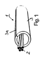
Die Fig. 1 zeigt eine perspektivische Ansicht eines Teils eines nach der Lehre der Erfindung
hergestellten optischen Kabels. Das optische Kabel 1 besteht aus den Lichtwellenleitern 2 und
dem die Lichtwellenleiter 2 umgebenden Metallrohr 3, welches eine Längsschweißnaht 3a
aufweist. Der Freiraum zwischen den Lichtwellenleitern 2 und dem Metallrohr 3 kann mit einem
sogenannten Petroleumjelly ausgefüllt sein, um eine Längswasserwanderung zu verhindern.
Die Lichtwellenleiter 2 haben eine größere Länge als das Metallrohr 3, verlaufen also wellen-,
wendel- oder sinusförmig in dem Metallrohr 3.Fig. 1 shows a perspective view of part of a according to the teaching of the invention
manufactured optical cable. The optical cable 1 consists of the
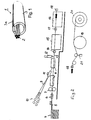
Fig. 2 zeigt eine seitliche Ansicht einer Fertigungsvorrichtung. Dort ist mit 4 ein Bandvorrat
bezeichnet, von dem ein Metallband 5 vorzugsweise ein Band aus nichtrostendem Stahl
kontinuierlich abgezogen wird. Mittels einer Bandbremse 6 wird das Band 5 abgebremst. Eine
Besäumschere 7 besäumt das Metallband 5 an seinen Längskanten, so daß zum einen stets
eine gleiche Bandbreite zum anderen metallisch reine Bandkanten vorliegen. In einer
Formvorrichtung 8 wird das Metallband 5 allmählich zum Schlitzrohr geformt. In das noch
offene Schlitzrohr werden Lichtwellenleiter 9, die von Vorratsspulen 10 abgezogen werden,
eingeführt. Mit 11 ist eine, Füllvorrichtung bezeichnet, die ein Petroleumjelly in das Schlitzrohr
einfüllt. Das Schlitzrohr wird mittels eines Laserschweißkopfes 12 an seinen Bandkanten
verschweißt, und das geschweißte Rohr 13 mittels einer Reduziereinrichtung 14
beispielsweise einer Ziehmatrize bzw. eines sog. Türkenkopfes in seinem Durchmesser
reduziert. Um die Kräfte aufzubringen, die für das Abziehen und Formen des Metallbandes 5
sowie das Herunterziehen des Metallrohres 13 notwendigen Kräfte werden mittels eines
Spannzangenabzuges 15 aufgebracht. Hinter dem Spannzangenabzug 15 ist ein weiterer
Spannzangenabzug 16 angeordnet. Zwischen den Spannzangenabzügen 15 und 16 ist eine
zweite Reduziereinrichtung 17 vorgesehen, die entweder eine Ziehmatrize oder ein
Türkenkopf sein kann.Fig. 2 shows a side view of a manufacturing device. There is a tape supply at 4
referred to, of which a
Hinter dem Spannzangenabzug 16 ist eine dritte Reduziereinrichtung 18 angeordnet. Die
Abzugskraft für das Rohr hinter der dritten Matrize 18 bzw. dem dritten Türkenkopf wird durch
einen Scheibenabzug 19 aufgebracht, um den das Rohr in mehreren Windungen herumgelegt
ist. Das von dem Scheibenabzug 19 ablaufende Rohr wird auf einen Aufwickler 20
aufgewickelt.A third reducing
Die Überlänge der Lichtwellenleiter 9 in dem Metallrohr 13 wird nun dadurch erzeugt, daß das
Metallrohr 13 zwischen der Reduziereinrichtung 18 und dem Scheibenabzug 19 elastisch
gedehnt wird. Hierzu wird in einfacher Weise an das Metallrohr 13 z. B. ein Gewicht 21
gehängt. Die elastische Dehnung wird auf dem Scheibenabzug 20 aufgehoben. Da die
Lichtwellenleiter 9 mit der gleichen Geschwindigkeit wie das elastisch gedehnte Metallrohr 13
abgezogen werden, ergibt sich bei Aufhebung der elastischen Dehnung eine Überlänge der
Lichtwellenleiter 9 in dem Metallrohr 13, die abhängig ist von der Größe des Gewichts 21.The excess length of the optical waveguide 9 in the
Die Abzugsgeschwindigkeit der Spannzangenabzüge 15 und 16 sowie des Scheibenabzugs
19 wird durch sogenannte nicht dargestellte Tänzereinrichtungen geregelt.The take-off speed of the
Wesentlich für die Erfindung ist, daß die Reduktion des Metallrohres 13 in der letzten
Ziehstufe, d. h. bei der dritten Reduzierstufe 18 am größten ist, um eine möglichst hohe
elastische Dehnung zu erzielen.It is essential for the invention that the reduction of the
Vorzugsweise ist die prozentuale Reduktion des Metallrohres 13 in der dritten Reduzierstufe
18 größer als die Summe der prozentualen Reduktionen des Metallrohres 13 in der ersten und
zweiten Reduziereinrichtung 14 und 17.The percentage reduction of the
Fig. 3 zeigt eine besonders vorteilhafte Ausgestaltung der Reduzierstufen 14, 17 und 18.3 shows a particularly advantageous embodiment of the
Der Ziehstein bzw. die Matrize 22 ist in einer Halterung 23 angeordnet, die wiederum in einer
Ziehsteinaufnahme 24 längsverschieblich gelagert ist. Am Eingang der Halterung 23 befindet
sich eine Rohrführung 26. Des weiteren ist in der Halterung 23 eine Öffnung 25 vorgesehen, in
welche Ziehöl in die Halterung 23 einfüllbar ist.The drawing die or the die 22 is arranged in a
Die Halterung 23 ist in der Ziehsteinaufnahme 24 über Tellerfedern 27 federnd gelagert. Die
Tellerfedern 27 werden vorgespannt, wenn das Metallrohr 13 gezogen wird.The
Mit 28 ist noch eine Tänzereinrichtung bezeichnet, welche die Abzugsgeschwindigkeit des Spannzangenabzuges regelt.With 28 a dancer device is also designated, which the withdrawal speed of the Collet trigger regulates.
Der Vorteil der federnden Lagerung der Halterung 23 in der Ziehsteinaufnahme 24 besteht
darin, daß bei einer Unterbrechung der Fertigung nach dem Zurücksetzen des Metallrohres 13
durch die Spannzangenabzüge zum Uberschweißen der Schweißnaht des Metallrohres 13 ein
stoßartiges Einsetzen des Ziehvorganges an den Reduzierstufen vermieden wird.The advantage of the resilient mounting of the
Es versteht sich von selbst, daß in jeder Reduzierstufe wahlweise eine Ziehmatrize oder ein Türkenkopf eingesetzt werden kann.It goes without saying that in each reduction stage either a drawing die or a Turkish head can be used.
Claims (10)
Applications Claiming Priority (2)
| Application Number | Priority Date | Filing Date | Title |
|---|---|---|---|
| DE19816998A DE19816998A1 (en) | 1998-04-17 | 1998-04-17 | Method of manufacturing an optical cable |
| DE19816998 | 1998-04-17 |
Publications (2)
| Publication Number | Publication Date |
|---|---|
| EP0950907A2 true EP0950907A2 (en) | 1999-10-20 |
| EP0950907A3 EP0950907A3 (en) | 2000-01-19 |
Family
ID=7864801
Family Applications (1)
| Application Number | Title | Priority Date | Filing Date |
|---|---|---|---|
| EP99400699A Ceased EP0950907A3 (en) | 1998-04-17 | 1999-03-19 | Method of fabricating an optical cable |
Country Status (5)
| Country | Link |
|---|---|
| US (1) | US6298542B1 (en) |
| EP (1) | EP0950907A3 (en) |
| CA (1) | CA2266816A1 (en) |
| DE (1) | DE19816998A1 (en) |
| NO (1) | NO991843L (en) |
Cited By (1)
| Publication number | Priority date | Publication date | Assignee | Title |
|---|---|---|---|---|
| CN105032965A (en) * | 2015-08-10 | 2015-11-11 | 西安西古光通信有限公司 | Metal composite belt longitudinal-covering forming device |
Families Citing this family (1)
| Publication number | Priority date | Publication date | Assignee | Title |
|---|---|---|---|---|
| EP3797891B1 (en) * | 2019-09-30 | 2023-08-02 | Nexans | Method for the continuous production of thin-walled hollow profiles with small diameters, corrugated in sections and made from non-ferrous metals |
Citations (6)
| Publication number | Priority date | Publication date | Assignee | Title |
|---|---|---|---|---|
| DE2851800A1 (en) * | 1978-11-30 | 1980-06-12 | Kabel Metallwerke Ghh | Multicore telecommunication cable - obtd. by surrounding moving core with metal strip coated with ethylene! copolymer and fusing with HF coil |
| EP0299123A2 (en) * | 1987-07-16 | 1989-01-18 | Laser Armor Tech Corporation | Apparatus and method for continuous manufacture of armoured optical fiber cable |
| WO1991001506A1 (en) * | 1989-07-24 | 1991-02-07 | Societe Foptica S.A. | Process and equipment for producing optical modules |
| DE4118004A1 (en) * | 1991-06-01 | 1992-12-03 | Kabelmetal Electro Gmbh | METHOD FOR PRODUCING STRAND-SHAPED GOODS PLATED WITH A LAYER OF ALUMINUM |
| DE4434134A1 (en) * | 1994-09-24 | 1996-03-28 | Kabelmetal Electro Gmbh | Process for producing a longitudinally welded metal tube |
| DE4434133A1 (en) * | 1994-09-24 | 1996-03-28 | Kabelmetal Electro Gmbh | Method of manufacturing an optical cable from a metal pipe |
Family Cites Families (15)
| Publication number | Priority date | Publication date | Assignee | Title |
|---|---|---|---|---|
| US2110965A (en) * | 1934-07-02 | 1938-03-15 | Tubus A G | Reducing the diameter of hollow metal articles |
| US3207651A (en) * | 1961-07-13 | 1965-09-21 | Procter & Gamble | Apparatus for making tubing from a continuous web |
| US3332138A (en) * | 1965-08-11 | 1967-07-25 | Gen Cable Corp | Method and apparatus for making precision sized tubing |
| DE1614657C3 (en) * | 1967-11-22 | 1975-03-27 | Siemens Ag, 1000 Berlin Und 8000 Muenchen | Process for reducing the gap between the cladding tube and the fuel filling of nuclear reactor fuel rods |
| US3668916A (en) * | 1970-01-19 | 1972-06-13 | Wean Ind Inc | Drawing of metal tubing |
| DE2401345A1 (en) * | 1974-01-09 | 1975-07-10 | Mannesmann Roehren Werke Ag | DRAWING-STRETCHING PROCESS FOR THE PRODUCTION OF LONG TUBES AND DEVICE FOR CARRYING OUT THE PROCESS |
| US3928997A (en) * | 1975-03-28 | 1975-12-30 | Olin Corp | Method and apparatus for producing corrugated tubing |
| US4090381A (en) * | 1975-06-23 | 1978-05-23 | Mikhail Vladimirovich Babasov | Device for drawing-off and straightening cylindrically shaped stock |
| US4079616A (en) * | 1976-03-19 | 1978-03-21 | Viktor Afanasievich Zazimko | Draw bench for producing cylindrical tubular items by drawing |
| IT1115656B (en) * | 1977-05-04 | 1986-02-03 | Pirelli | METHOD OF PRODUCTION OF COMPONENTS OF TELECOMMUNICATION CABLES AND SYSTEM FOR REALIZING IT |
| US4291565A (en) * | 1979-08-22 | 1981-09-29 | Asa Enterprises, Inc. | Wire drawing device |
| US4441830A (en) * | 1982-03-29 | 1984-04-10 | Ncr Corporation | Printing solenoid |
| DE3612805C2 (en) * | 1986-04-16 | 1995-06-14 | Kabelmetal Electro Gmbh | Method and device for producing an elongate good with a hollow cylindrical cross section |
| EP0465656A4 (en) * | 1989-12-05 | 1992-06-03 | Nkk Corporation | Apparatus for and method of manufacturing optical fiber cable covered with metal pipe |
| DE19501945A1 (en) * | 1995-01-24 | 1996-07-25 | Alcatel Kabel Ag | Method for producing longitudinally welded metal pipes |
-
1998
- 1998-04-17 DE DE19816998A patent/DE19816998A1/en not_active Withdrawn
-
1999
- 1999-03-19 EP EP99400699A patent/EP0950907A3/en not_active Ceased
- 1999-04-12 CA CA002266816A patent/CA2266816A1/en not_active Abandoned
- 1999-04-16 NO NO991843A patent/NO991843L/en not_active Application Discontinuation
- 1999-04-16 US US09/292,956 patent/US6298542B1/en not_active Expired - Fee Related
Patent Citations (6)
| Publication number | Priority date | Publication date | Assignee | Title |
|---|---|---|---|---|
| DE2851800A1 (en) * | 1978-11-30 | 1980-06-12 | Kabel Metallwerke Ghh | Multicore telecommunication cable - obtd. by surrounding moving core with metal strip coated with ethylene! copolymer and fusing with HF coil |
| EP0299123A2 (en) * | 1987-07-16 | 1989-01-18 | Laser Armor Tech Corporation | Apparatus and method for continuous manufacture of armoured optical fiber cable |
| WO1991001506A1 (en) * | 1989-07-24 | 1991-02-07 | Societe Foptica S.A. | Process and equipment for producing optical modules |
| DE4118004A1 (en) * | 1991-06-01 | 1992-12-03 | Kabelmetal Electro Gmbh | METHOD FOR PRODUCING STRAND-SHAPED GOODS PLATED WITH A LAYER OF ALUMINUM |
| DE4434134A1 (en) * | 1994-09-24 | 1996-03-28 | Kabelmetal Electro Gmbh | Process for producing a longitudinally welded metal tube |
| DE4434133A1 (en) * | 1994-09-24 | 1996-03-28 | Kabelmetal Electro Gmbh | Method of manufacturing an optical cable from a metal pipe |
Cited By (1)
| Publication number | Priority date | Publication date | Assignee | Title |
|---|---|---|---|---|
| CN105032965A (en) * | 2015-08-10 | 2015-11-11 | 西安西古光通信有限公司 | Metal composite belt longitudinal-covering forming device |
Also Published As
| Publication number | Publication date |
|---|---|
| EP0950907A3 (en) | 2000-01-19 |
| US6298542B1 (en) | 2001-10-09 |
| DE19816998A1 (en) | 1999-10-21 |
| CA2266816A1 (en) | 1999-10-17 |
| NO991843D0 (en) | 1999-04-16 |
| NO991843L (en) | 1999-10-18 |
Similar Documents
| Publication | Publication Date | Title |
|---|---|---|
| EP0703017B1 (en) | Method for the production of longitudinally seam welded metal tubes | |
| EP0703478B1 (en) | Method of manufacture of an optical cable from a metal tube | |
| EP0917746A1 (en) | Method and device for the twisting of at least two single-lines | |
| DE3808037C2 (en) | Method for producing an optical cable and device for carrying it out | |
| EP0313896A1 (en) | Manufacturing method and device for manufacturing optical cables | |
| DE69733053T2 (en) | Manufacturing process of an optical cable with SZ guide grooves | |
| EP0007473A1 (en) | Device for SZ stranding power current cable cores with a sector-shaped conductor cross-section | |
| DE19741934C2 (en) | Device and method for controlling the upsetting of a metal tube with at least one internal optical waveguide | |
| DE3027743C2 (en) | ||
| DE2508385A1 (en) | DEVICE FOR TWISTING A LADDER | |
| EP1103013B1 (en) | Method of producing an optical cable with an excessive length of the optical waveguides | |
| EP0950907A2 (en) | Method of fabricating an optical cable | |
| DE4323649A1 (en) | Process for producing a helically or annularly corrugated metal tube | |
| EP0962801B1 (en) | Apparatus for optical cable manufacturing | |
| CH634119A5 (en) | METHOD AND DEVICE FOR THE CONTINUOUS PRODUCTION OF STRAND-SHAPED GOODS BY LEADING STRAPS. | |
| DE3910122C2 (en) | ||
| DE877327C (en) | Method for attaching a pulling device to a metal pipe, especially when pulling down metal pipes for sheathing electrical cables | |
| EP0842716A2 (en) | Process and device for the manufacture of long lengths of metallic tubes | |
| EP1321568A2 (en) | Wire rope with several strands and method and device for introducing a support strand | |
| DE3422803C2 (en) | ||
| DE2153934A1 (en) | Straight seam welded tube making plant - has floating tube welding station | |
| AT394467B (en) | Method and apparatus for fitting a flexible metallic screen (shield) consisting of individual wires around a cable core | |
| EP1595610B1 (en) | Method for the continuous production of longitudinally seam welded metal tubes | |
| DE102022126542A1 (en) | Processing unit for processing at least one line bundle consisting of several individual lines | |
| DE2521144A1 (en) | METHOD OF PULLING PIPES |
Legal Events
| Date | Code | Title | Description |
|---|---|---|---|
| PUAI | Public reference made under article 153(3) epc to a published international application that has entered the european phase |
Free format text: ORIGINAL CODE: 0009012 |
|
| AK | Designated contracting states |
Kind code of ref document: A2 Designated state(s): AT CH DE DK ES FI FR GB GR IT LI NL SE |
|
| AX | Request for extension of the european patent |
Free format text: AL;LT;LV;MK;RO;SI |
|
| PUAL | Search report despatched |
Free format text: ORIGINAL CODE: 0009013 |
|
| 17P | Request for examination filed |
Effective date: 19991103 |
|
| RTI1 | Title (correction) |
Free format text: METHOD OF FABRICATING AN OPTICAL CABLE |
|
| AK | Designated contracting states |
Kind code of ref document: A3 Designated state(s): AT BE CH CY DE DK ES FI FR GB GR IE IT LI LU MC NL PT SE |
|
| AX | Request for extension of the european patent |
Free format text: AL;LT;LV;MK;RO;SI |
|
| RTI1 | Title (correction) |
Free format text: METHOD OF FABRICATING AN OPTICAL CABLE |
|
| AKX | Designation fees paid |
Free format text: AT CH DE DK ES FI FR GB GR IT LI NL SE |
|
| RAP1 | Party data changed (applicant data changed or rights of an application transferred) |
Owner name: NEXANS |
|
| 17Q | First examination report despatched |
Effective date: 20030514 |
|
| STAA | Information on the status of an ep patent application or granted ep patent |
Free format text: STATUS: THE APPLICATION HAS BEEN REFUSED |
|
| 18R | Application refused |
Effective date: 20030719 |