EP0950519A1 - Method for self-adjusting the printing and the cutting register in rotary printing machines with several webs - Google Patents
Method for self-adjusting the printing and the cutting register in rotary printing machines with several webs Download PDFInfo
- Publication number
- EP0950519A1 EP0950519A1 EP98810329A EP98810329A EP0950519A1 EP 0950519 A1 EP0950519 A1 EP 0950519A1 EP 98810329 A EP98810329 A EP 98810329A EP 98810329 A EP98810329 A EP 98810329A EP 0950519 A1 EP0950519 A1 EP 0950519A1
- Authority
- EP
- European Patent Office
- Prior art keywords
- web
- color
- calculated
- drive
- register
- Prior art date
- Legal status (The legal status is an assumption and is not a legal conclusion. Google has not performed a legal analysis and makes no representation as to the accuracy of the status listed.)
- Granted
Links
Images

Classifications
-
- B—PERFORMING OPERATIONS; TRANSPORTING
- B41—PRINTING; LINING MACHINES; TYPEWRITERS; STAMPS
- B41F—PRINTING MACHINES OR PRESSES
- B41F33/00—Indicating, counting, warning, control or safety devices
-
- B—PERFORMING OPERATIONS; TRANSPORTING
- B41—PRINTING; LINING MACHINES; TYPEWRITERS; STAMPS
- B41F—PRINTING MACHINES OR PRESSES
- B41F13/00—Common details of rotary presses or machines
- B41F13/02—Conveying or guiding webs through presses or machines
- B41F13/025—Registering devices
-
- B—PERFORMING OPERATIONS; TRANSPORTING
- B41—PRINTING; LINING MACHINES; TYPEWRITERS; STAMPS
- B41F—PRINTING MACHINES OR PRESSES
- B41F13/00—Common details of rotary presses or machines
- B41F13/08—Cylinders
- B41F13/10—Forme cylinders
- B41F13/12—Registering devices
-
- B—PERFORMING OPERATIONS; TRANSPORTING
- B41—PRINTING; LINING MACHINES; TYPEWRITERS; STAMPS
- B41P—INDEXING SCHEME RELATING TO PRINTING, LINING MACHINES, TYPEWRITERS, AND TO STAMPS
- B41P2213/00—Arrangements for actuating or driving printing presses; Auxiliary devices or processes
- B41P2213/70—Driving devices associated with particular installations or situations
- B41P2213/73—Driving devices for multicolour presses
- B41P2213/734—Driving devices for multicolour presses each printing unit being driven by its own electric motor, i.e. electric shaft
Definitions
- the invention relates to the field of printing technology. It goes out of a method for self-adjusting color and cut register control in rotary printing presses with single or multiple webs according to the Preamble of the first claim.
- the invention is particularly advantageous for shaftless rotary printing presses used.
- a shaftless rotary printing machine with pairs rubber blanket and plate or Forme cylinders are described in DE 43 44 896 A1.
- a process of regulation the drive for the transport of a paper web of a printing press which is particularly suitable for shaftless rotary printing machines the unpublished European patent application no. 98101727.0.
- the speed control of the web train determining Elements depending on a load torque as specified a load characteristic curve lowered or raised, so that the drive at the same time the command variables speed and drive torque or web tension and that the master setpoint compensates according to the load characteristic becomes.
- a major advantage of individually driven rotary printing machines is that these machines are capable of changing products machine running.
- the methods described in the patent application are the web tension changes, due to the starting and stopping required when changing the product of pressure points and when changing paper types while the machine is running usually arise, largely avoided.
- the achieved with it Stability with regard to the transport of a paper web of a printing press is excellent.
- the object of the invention is therefore a method for self-adjusting Specify register control in rotary printing presses with multiple webs at what influencing factors on the color and cut register, such as a change of paper type or the content of the printed product while it is running Machine, dry or damp paper, different number of pressure points per paper web, different paper lengths, etc. in all possible Operating modes of the machine are recorded at the origin and controlling the Apply setpoints for the color and cut registers.
- Each tension element of the Paper web is advantageously via a control device according to the mentioned unpublished European patent application operated.
- the essence of the invention is that a correction value from the operating points, i.e. especially from the current speed of rotation and the torque, the servomotors for the tension elements of the paper web are calculated and the Reference variables for positioning the color and cut registers are activated becomes.
- the operating points of the actuators react extremely quickly Changes in paper properties, resulting in a high dynamic with short Response times for influencing the register results.
- a measure of the relative paper elongation calculate per section from the operating points of the drives and in Activate the register individually in the form of a correction variable.
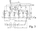
- the method according to the invention for self-adjusting color and cut register control for rotary printing machines with a plurality of webs is explained in more detail below with the aid of FIG. 3 .
- the devices according to the inventive method are designated KORR and KONF, the corresponding signals with k .. 3, the influences of the web back 9 and the other webs 10, 11 are only shown in summary.
- k xn represents the operating points of the servomotors
- k yn the correction values for the control devices of all other elements involved in the transport of the train.
- the KONF module does not only contain the machine configuration data for the current one, but also the data for the next production.
- the Application of the method according to the invention taking into account the Machine configuration data for the next production thus allows that when changing production with a changing paper type or printing point configuration this change simultaneously in the form of a correction to the relevant Reference variables for the color and cut registers can be switched on can. In terms of response time, this correction is many times faster than the register control according to the state of the art. The latter only serves to compensate for any residual errors. This results in a generally valid solution for all operating cases of a printing press for fast self-adjusting Color and cut register control.
Abstract
Description
Die Erfindung bezieht sich auf das Gebiet der Drucktechnik. Sie geht aus von einem Verfahren zur selbsteinstellenden Farb- und Schnittregistersteuerung in Rotationsdruckmaschinen mit einzelnen oder mehreren Bahnen gemäss dem Oberbegriff des ersten Anspruchs.The invention relates to the field of printing technology. It goes out of a method for self-adjusting color and cut register control in rotary printing presses with single or multiple webs according to the Preamble of the first claim.
Die Erfindung wird insbesondere mit Vorteil für wellenlose Rotationsdruckmaschinen eingesetzt. Eine wellenlose Rotationsdruckmaschine mit paarweise zu Zylindergruppen zusammengefassten Gummituch- und Platten- bzw. Formzylindern wird in der DE 43 44 896 A1 beschrieben. Ein Verfahren zur Regelung des Antriebes für den Transport einer Papierbahn einer Druckmaschine, das insbesondere für wellenlose Rotationsdruckmaschinen geeignet ist, beschreibt die nicht vorveröffentlichte Europäische Patentanmeldung Nr. 98101727.0. Nach diesem Verfahren wird die Drehzahlregelung der bahnzugbestimmenden Elemente in Abhängigkeit eines Lastdrehmomentes nach Massgabe einer Belastungskennlinie abgesenkt oder angehoben, so dass der Antrieb gleichzeitig die Führungsgrössen Drehzahl und Antriebsmoment bzw. Bahnspannung einstellt und dass der Leitsollwert nach Massgabe der Belastungskennlinie kompensiert wird. The invention is particularly advantageous for shaftless rotary printing presses used. A shaftless rotary printing machine with pairs rubber blanket and plate or Forme cylinders are described in DE 43 44 896 A1. A process of regulation the drive for the transport of a paper web of a printing press, which is particularly suitable for shaftless rotary printing machines the unpublished European patent application no. 98101727.0. According to this method, the speed control of the web train determining Elements depending on a load torque as specified a load characteristic curve lowered or raised, so that the drive at the same time the command variables speed and drive torque or web tension and that the master setpoint compensates according to the load characteristic becomes.
Ein wesentlicher Vorteil von einzeln angetriebenen Rotationsdruckmaschinen ist, dass diese Maschinen in der Lage sind, einen Produktwechsel bei laufender Maschine durchzuführen. Mit dem in der oben genannten Europäischen Patentanmeldung beschriebenen Verfahren werden die Bahnspannungsänderungen, die durch das beim Produktwechsel erforderliche An- und Abstellen von Druckstellen sowie bei einem Papiersortenwechsel bei laufender Maschine üblicherweise entstehen, grösstenteils vermieden. Die damit erreichte Stabilität betreffend Transport einer Papierbahn einer Druckmaschine ist ausgezeichnet.A major advantage of individually driven rotary printing machines is that these machines are capable of changing products machine running. With the European in the above The methods described in the patent application are the web tension changes, due to the starting and stopping required when changing the product of pressure points and when changing paper types while the machine is running usually arise, largely avoided. The achieved with it Stability with regard to the transport of a paper web of a printing press is excellent.
Trotz der ausgezeichneten Stabilität betreffend Transport einer Papierbahn wird damit ein Problem insbesondere bei Produktewechsel oder Papiersortenwechsel bei laufender Maschine nicht oder nur teilweise gelöst, nämlich die druckqualitätsbestimmende Positionierung der Farb- und Schnittregister.Despite the excellent stability regarding the transport of a paper web becomes a problem especially when changing products or changing paper types not or only partially solved with the machine running, namely the Positioning of the color and cut registers that determine print quality.
Farb- und Schnittregister werden nach dem Stand der Technik gemäss Fig. 2 durch eigenständige Messglieder beeinflusst, indem die durch die Messglieder erfassten Regelgrössen den Positionierführungsgrössen zugeschaltet werden und damit die einzelnen Stellglieder hinsichtlich Farbregister und alle gemeinsam hinsichtlich Schnittregister einstellen. Bei geteilten Bahnen wird das Schnittregister mittels zusätzlichen Stellgliedern (Nebenregister) eingestellt (nicht dargestellt). Diese Einrichtungen haben den Nachteil, dass:
- bei Anfahrvorgängen die Führungsgrössen auf fixe Referenzwerte gestellt werden und dadurch häufig manuelle Eingriffe durch die Drucker erfordern.
- die Messglieder erst auf die Dehnung der Papierbahn reagieren.
- die Reaktionszeit der Messung aufgrund der Totzeiten beim Transport der Bahn bis zum Messglied, bei der Analyse und der Datenübertragung zur Steuerung typisch 2s beträgt und die Güte der erfassten Istwerte von der Laufruhe der Bahn abhängt.
- die Zug- / Dehnungsverhältnisse einer gesamten Produktion mit mehreren Bahnen durch Rückwirkung der über die gemeinsame Sammelwalze laufenden Bahnen untereinander erheblich beeinflusst werden.
- When starting up, the command variables are set to fixed reference values and therefore often require manual intervention by the printer.
- the measuring elements only react to the stretching of the paper web.
- the reaction time of the measurement is typically 2s due to the dead times during the transport of the web to the measuring element, during the analysis and the data transfer to the control, and the quality of the actual values recorded depends on the smoothness of the web.
- the tensile / elongation conditions of an entire production with several webs can be significantly influenced by the interaction of the webs running over the common collecting roller.
Fazit: Beim Stand der Technik lässt man im ersten Moment eine Ungenauigkeit der Registerführung bezüglich Farbe und Schnitt zu, bevor man relativ träge über zusätzliche Messglieder korrigierend auf die Führungsgrössen einwirkt.Conclusion: With the state of the art, you leave an inaccuracy at first the register guide in terms of color and cut before you get relative has a sluggish effect on the command variables via additional measuring elements.
Aufgabe der Erfindung ist es deshalb, ein Verfahren zur selbsteinstellenden Registersteuerung in Rotationsdruckmaschinen mit mehreren Bahnen anzugeben, bei welchem Einflussgrössen auf die Farb- und Schnittregister, wie z.B. ein Wechsel der Papiersorte oder des Inhalts des gedruckten Produktes bei laufender Maschine, trockenes oder feuchtes Papier, unterschiedliche Anzahl Druckstellen pro Papierbahn, unterschiedliche Papierlängen, usw. in allen möglichen Betriebsarten der Maschine am Ursprung erfasst werden und steuernd auf die Sollwerte für die Farb- und Schnittregister einwirken. Jedes Zugelement der Papierbahn wird dabei vorteilhaft über eine Regeleinrichtungen gemäss der erwähnten, nicht vorveröffentlichten Europäischen Patentanmeldung betrieben.The object of the invention is therefore a method for self-adjusting Specify register control in rotary printing presses with multiple webs at what influencing factors on the color and cut register, such as a change of paper type or the content of the printed product while it is running Machine, dry or damp paper, different number of pressure points per paper web, different paper lengths, etc. in all possible Operating modes of the machine are recorded at the origin and controlling the Apply setpoints for the color and cut registers. Each tension element of the Paper web is advantageously via a control device according to the mentioned unpublished European patent application operated.
Kern der Erfindung ist es, dass ein Korrekturwert aus den Arbeitspunkten, d.h. insbesondere aus der aktuellen Drehgeschwindigkeit und dem Drehmoment, der Stellmotoren für die Zugelemente der Papierbahn berechnet und den Führungsgrössen für die Positionierung der Farb- und Schnittregister aufgeschaltet wird. Die Arbeitspunkte der Stellmotoren reagieren extrem rasch auf Änderungen der Papiereigenschaft, wodurch sich eine hohe Dynamik mit kurzen Reaktionszeiten bezüglich Einflussnahme auf die Register ergibt. Da die Bahnlänge der Teilstrecken zwischen den Zugelementen der Papierbahnen einer laufenden Produktion bekannt sind, lässt sich ein Mass für die relative Papierdehnung pro Teilstrecke aus den Arbeitspunkten der Antriebe berechnen und in Form einer Korrekturgrösse den Registern individuell zuschalten. Obschon die konkrete Einflussnahme dieser Korrekturgrössen auf die Farb- und Schnittregister unterschiedlich ist, bleibt das Verfahren für beide Register grundsätzlich das gleiche.The essence of the invention is that a correction value from the operating points, i.e. especially from the current speed of rotation and the torque, the servomotors for the tension elements of the paper web are calculated and the Reference variables for positioning the color and cut registers are activated becomes. The operating points of the actuators react extremely quickly Changes in paper properties, resulting in a high dynamic with short Response times for influencing the register results. Because the web length of the sections between the tension elements of the paper webs of a running one Production are known, a measure of the relative paper elongation calculate per section from the operating points of the drives and in Activate the register individually in the form of a correction variable. Although that concrete influence of these correction parameters on the color and cut register is different, the procedure remains the same for both registers same.
Bei Wechsel des Inhalts des gedruckten Produktes bei laufender Maschine sind sowohl die Bahnstrecken der laufenden wie auch diejenigen der nächsten Produktion bekannt. Somit kann die Einflussnahme der neuen Bahnstrecken auf die Register unmittelbar beim Produktionswechsel gemäss dem erfindungsgemässen Verfahren erfolgen.When changing the content of the printed product while the machine is running are both the current and the next rail routes Production known. Thus, the influence of the new railway lines on the registers immediately when changing production according to the invention Procedure.
Im Vergleich zum Betrieb nach dem Stand der Technik ergeben sich insbesondere bei Wechsel der Papiersorte oder des Inhalts des gedruckten Produktes bei laufender Maschine werden markante Vorteile, dadurch dass
- durch die gesteuerte Korrektur aller Register ein insgesamt konstantes Verhalten der Papierbahnen resultiert.
- die Farbregister aufgrund der gesteuerten Einflussnahme reaktionsschnell voreingestellt werden,
- die Schnittlage aufgrund der gesteuerten Einflussnahme auf alle die Schnittlage bestimmenden Bahnzugelemente reaktionsschnell voreingestellt werden.
- durch eine verbesserte Farb- und Registereinhaltung in allen Phasen des Betriebs weniger Makulatur erzeugt wird,
- The controlled correction of all registers results in an overall constant behavior of the paper webs.
- the color registers are quickly preset based on the controlled influence,
- the cutting position can be preset quickly in response to the controlled influence on all web tension elements determining the cutting position.
- Less waste is generated in all phases of operation thanks to improved color and register maintenance,
Der Druckprozess wird somit insgesamt besser beherrschbar. Weitere vorteilhafte Ausführungsformen ergeben sich aus den entsprechenden abhängigen Ansprüchen.The printing process is thus easier to control overall. More beneficial Embodiments result from the corresponding dependent Claims.
Nachfolgend wird die Erfindung anhand von Ausführungsbeispielen im
Zusammenhang mit den Zeichnungen näher erläutert. Es zeigen:
Die in den Zeichnungen verwendeten Bezugszeichen und deren Bedeutung sind in der Bezugszeichenliste zusammengefasst aufgelistet. Grundsätzlich sind in den Figuren gleiche Teile mit gleichen Bezugszeichen versehen.The reference symbols used in the drawings and their meaning are summarized in the list of reference symbols. Are basically In the figures, the same parts are provided with the same reference symbols.
Das erfindungsgemässe Verfahren zur selbsteinstellenden Farb- und
Schnittregistersteuerung für Rotationsdruckmaschinen mit mehreren Bahnen
wird im folgenden mit Hilfe der Figur 3 näher erläutert. Die Einrichtungen nach
dem erfindungsgemässen Verfahren sind mit KORR und KONF, die entsprechenden
Signale mit k.. bezeichnet. Zur Förderung der Übersicht von Fig. 3 sind
die Einflüsse der Bahnrückseite 9 und der übrigen Bahnen 10, 11 nur summarisch
dargestellt. So repräsentiert kxn die Arbeitspunkte der Stellmotoren bzw.
kyn die Korrekturgrössen für die Regeleinrichtungen aller übrigen am Transport
der Bahn beteiligten Elemente.The method according to the invention for self-adjusting color and cut register control for rotary printing machines with a plurality of webs is explained in more detail below with the aid of FIG. 3 . The devices according to the inventive method are designated KORR and KONF, the corresponding signals with k .. 3, the influences of the web back 9 and the
Aus Figur 3 ist ersichtlich, dass die konventionelle Farb- und Schnittregisterregelung in Analogie zur Figur 2 übernommen wurde; ihr Einsatz ist aber optional und ist nicht Bedingung. Es bilden:
- die Führungsgrösse WVW und Regler RVW und Antrieb M die Regeleinrichtung für das Vorspannwerk,
- die Führungsgrösse WD1 und Regler RD1 und Antrieb M die Regeleinrichtung für das erste Druckwerk,
- die Führungsgrösse WDn und Regler RDn und Antrieb M die Regeleinrichtung ersatzweise für alle übrigen Druckwerke,
- die Führungsgrösse WZW und Regler RZW und Antrieb M die Regeleinrichtung für die Zugwalze,
- die Führungsgrösse WSW und Regler RSW und Antrieb M die Regeleinrichtung für die Trichtereinlaufzugwalze,
Messfühler 12 und Farbregister-Messystem MF das Messglied für die Farbregister,Messfühler 13 und Schnittregister-Messystem MS das Messglied für die Schnittregister.
- the command variable W VW and controller R VW and drive M the control device for the prestressing unit,
- the command variable W D1 and controller R D1 and drive M the control device for the first printing unit,
- the command variable W Dn and controller R Dn and drive M the control device as a replacement for all other printing units,
- the command variable W ZW and controller R ZW and drive M the control device for the pull roller,
- the command variable W SW and controller R SW and drive M the control device for the hopper feed roller,
- Measuring
sensor 12 and color register measuring system M F the measuring element for the color register, -
Sensor 13 and cutting register measuring system M S the measuring element for the cutting register.
Diese konventionellen Einrichtungen werden durch Einrichtungen nach
dem erfindungsgemässen Verfahren dadurch ergänzt, dass der Hauptführungsgrösse
Wv die Korrekturgrösse kyS als Positionsoffset für das Schnittregister und
den einzelnen Druckwerken die Korrekturgrösse kyF1...kyFn als Positionsoffset
für die Farbregister zugeschaltet wird. Die Berechnung der Korrekturgrössen
erfolgt im Modul KORR aus den Arbeitspunkten aller Antriebe, d.h. insbesondere
der aktuellen Drehgeschwindigkeit und dem Drehmoment derjenigen Antriebe,
welche sich am Transport der Bahnen beteiligen, d.h. aus dem Antrieb für das
Vorspannwerk 3, aus den angestellten Druckwerken 4, aus der Zugwalze 6 und
aus der Trichtereinlaufzugwalze 7 sowie sinngemäss aus allen nicht dargestellten
Einrichtungen der Bahnrückseite und der übrigen Bahnen 10, 11. Die Antriebe
reagieren mit einer Änderung der Antriebsdrehzahl und der Bahnspannung
auf Lastdrehmomentänderungen; es stellt sich somit ein neuer Antriebs-Arbeitspunkt
im Drehzahl-Bahnspannungs-Diagramm ein. Die derart erfassten
Arbeitspunkte kxVW, kxD1, kxDn, kxZW und kxSW sind in Figur 3 explizit für die
Bahnoberseite der Bahn 9 dargestellt; sie werden sinngemäss für die Bahnrückseite
und alle übrigen Bahnen erfasst und sind durch kxn dargestellt. Die für das
Registerverhalten wichtige Papierdehnung der Bahn verhält sich gemäss einer
bestimmten Funktion zum Lastdrehmoment und lässt sich - zusammen mit der
Bahnstreckenlänge bis zum nächsten Antrieb - direkt aus dem Arbeitspunkt des
Stellmotors berechnen. Die entsprechende allgemeine Formel für das Mass der
Papierdehnung lautet:
- λ =
- Bahnverlängerung in m
- σ =
- Zugbeanspruchung der Bahn in dN/m = f (Lastdrehmomente)
- L =
- Bahnstreckenlänge in m
- E =
- Elastizitätsmodul in N/m = f (Lastdrehmomente, Geschwindigkeiten)
- λ =
- Web extension in m
- σ =
- Train tension in dN / m = f (load torques)
- L =
- Track length in m
- E =
- Elastic modulus in N / m = f (load torques, speeds)
Die Ermittlung des Masses für die Papierdehnungen erfolgt im Modul
KORR; die hierzu benötigten Bahnstreckenlängen sind für jede Produktion bekannt
und sind im Modul KONF abgelegt. Die anteilige Einflussnahme der erfassten
Massgabe für die relativen Bahndehnungen auf die Farb- und Schnittregister,
d.h. die Ermittlung der Korrekturgrössen kyF1...kyFn, kyS, bzw.kyn, erfolgt
ebenfalls im Modul KORR anhand der im Modul KONF abgelegten Maschinenkonfiguration.
Diese Berechnung der einzelnen Korrekturgrössen erfolgt nach
der allgemeinen Formel
- kym =
- m-te Korrekturgrösse, d.h. kyF1...kyFn, kyS oder kyn
- KONF =
- Konfigurationsdaten einer Produktion
- kx1 =
- Arbeitspunkt des ersten Antriebs einer Produktion
- kxm =
- Arbeitspunkt des letzten Antriebs einer Produktion
- k ym =
- mth correction variable , ie k yF1 ... k yFn , k yS or k yn
- CONF =
- Configuration data of a production
- k x1 =
- Working point of the first drive of a production
- k xm =
- Working point of the last drive of a production
Die derart berechneten Grössen sind in Figur 3 explizit für die Bahnoberseite
der Bahn 9 dargestellt; sie werden sinngemäss für die Bahnrückseite und
alle übrigen Bahnen berechnet und sind durch kyn dargestellt.The variables calculated in this way are shown explicitly in FIG. 3 for the upper side of the
Wird dieses Verfahren auf alle die Papierbahn antreibenden Antriebe sowie auf alle Bahnen angewendet, so gewinnt man nahezu verzögerungsfrei Rückschlüsse auf die effektiven Papiereigenschaften aller Bahnen und kann damit über die Korrekturgrössen kyF1...kyFn, kyS, bzw.kyn korrigierend auf die Führungsgrössen für die Farb- und Schnittregister einwirken.If this method is applied to all drives driving the paper web as well as to all webs, conclusions can be drawn almost instantaneously on the effective paper properties of all webs and can be corrected using the correction parameters k yF1 ... k yFn , k yS , or k yn the reference variables for the color and cut registers act.
Im Modul KONF sind nicht nur die Daten der Maschinenkonfiguration für die laufende, sondern auch die Daten für die nächste Produktion abgelegt. Die Anwendung des erfindungsgemässen Verfahrens unter Berücksichtigung der Maschinenkonfigurationsdaten für die nächste Produktion gestattet damit, dass bei einem Produktionswechsel mit sich ändernder Papiersorte bzw. Druckstellenkonfiguration diese Änderung gleichzeitig in Form einer Korrektur den relevanten Führungsgrössen für die Farb- und Schnittregister zugeschaltet werden kann. Diese Korrektur ist bezüglich Reaktionszeit um ein Vielfaches rascher als die Registerregelung nach dem Stand der Technik. Letztere dient lediglich dazu, allfällige Restfehler auszugleichen. Damit ergibt sich eine allgemein gültige Lösung für alle Betriebsfalle einer Druckmaschine zur schnellen selbsteinstellenden Farb- und Schnittregistersteuerung. The KONF module does not only contain the machine configuration data for the current one, but also the data for the next production. The Application of the method according to the invention taking into account the Machine configuration data for the next production thus allows that when changing production with a changing paper type or printing point configuration this change simultaneously in the form of a correction to the relevant Reference variables for the color and cut registers can be switched on can. In terms of response time, this correction is many times faster than the register control according to the state of the art. The latter only serves to compensate for any residual errors. This results in a generally valid solution for all operating cases of a printing press for fast self-adjusting Color and cut register control.
- 11
- RollenwechslerReel changer
- 22nd
- PendelwalzePendulum roller
- 33rd
- VorspannwerkLeader
- 44th
- Druckstelle, angestelltPressure point, employed
- 55
- Druckstelle, abgestelltPressure point, turned off
- 66
- ZugwalzePull roller
- 77
- TrichtereinlaufzugwalzeHopper feed roller
- 88th
- Falzmesser im FalzapparatFolding knife in the folder
- 99
- Bahn ALane A
- 1010th
- Bahn BLane B
- 1111
- Bahn CLane C
- 1212th
- Messfühler für die Erfassung der FarbregisterSensor for the registration of the color register
- 1313
- Messfühler für die Erfassung der SchnittlageMeasuring sensor for the detection of the cutting position
- L1...L9L1 ... L9
- Bahnstrecken zwischen zwei angetriebenen MaschinenelementenRailway lines between two driven machine elements
- MM
- Stellglied, bestehend aus Umrichter und MotorActuator, consisting of converter and motor
- Wv W v
- Führungsgrösse Maschinendrehzahl/SchnittlageCommand variable machine speed / cutting position
- WVW W VW
- Führungsgrösse Drehzahl/Position für das VorspannwerkCommand variable speed / position for the pretensioner
- RVW R VW
- Regler für das VorspannwerkRegulator for the leader
- WD1...WDn W D1 ... W Dn
-
Führungsgrösse Drehzahl/Position für das Druckwerk 1 bzw. das
Druckwerk nCommand variable speed / position for
printing unit 1 or the Printing unit n - RD1...RDn R D1 ... R Dn
-
Regler für das Druckwerk 1 bzw. das Druckwerk nController for
printing unit 1 or printing unit n - WZW W ZW
- Führungsgrösse Drehzahl/Position für die ZugwalzeCommand variable speed / position for the pull roller
- RZW R ZW
- Regler für die ZugwalzeController for the pull roller
- WSW W SW
- Führungsgrösse Drehzahl/Position für die TrichtereinlaufzugwalzeCommand variable speed / position for the hopper feed roller
- RSW R SW
- Regler für die TrichtereinlaufzugwalzeRegulator for the hopper feed roller
- KORRCORR
- Modul für die Berechnung der Korrekturgrössen für Farb- und SchnittregisterModule for the calculation of correction values for color and cut registers
- KONFCONF
- Konfigurationsdaten der Maschine für die laufende und die nächste ProduktionConfiguration data of the machine for the current and the next production
- kxVW k xVW
- Mass für den Arbeitspunkt Vorspannwerk Measure for the pre-tensioning unit working point
- kxD1...kxDn k xD1 ... k xDn
-
Mass für die Arbeitspunkte Druckwerk 1 bzw. Druckwerk nMeasure for the working
points printing unit 1 or printing unit n - kxZW k xZW
- Mass für den Arbeitspunkt ZugwalzeMeasure for the working point of the pull roller
- kxSW k xSW
- Mass für den Arbeitspunkt TrichtereinlaufzugwalzeMeasure for the working point of the funnel infeed roller
- kxn k xn
- Repräsentatives Mass für die Arbeitspunkte aller nicht dargestellten, angetriebenen MaschinenelementeRepresentative measure for the working points of all not shown driven machine elements
- kyS k yS
- Korrekturgrösse SchnittlageCorrection size cut position
- kyF1...kyFn k yF1 ... k yFn
-
Korrekturgrösse Farbregister 1 bzw. Farbregister nCorrection
size color register 1 or color register n - kyn k yn
- Repräsentative Korrekturgrösse für die Beeinflussung aller nicht dargestellten FührungsgrössenRepresentative correction quantity for influencing all not shown Leading variables
- MF M F
- Farbregister-MessystemColor register measuring system
- MS M S
- Schnittlage-MessystemCutting position measuring system
- xS x p
- Regelgrösse SchnittlageRegular size of cut
- xF1...xFn x F1 ... x Fn
- Regelgrösse FarbregisterStandard size color register
- λ =λ =
- Bahnverlängerung in mWeb extension in m
- σ =σ =
- Zugbeanspruchung der Bahn in dN/m = f (Lastdrehmomente)Train tension in dN / m = f (load torques)
- L =L =
- Bahnstreckenlänge in mTrack length in m
- E =E =
- Elastizitätsmodul in N/m = f (Lastdrehmomente, Geschwindigkeiten)Elastic modulus in N / m = f (load torques, speeds)
Claims (5)
Priority Applications (9)
| Application Number | Priority Date | Filing Date | Title |
|---|---|---|---|
| DE59801305T DE59801305D1 (en) | 1998-04-16 | 1998-04-16 | Process for self-adjusting color and cut register control in rotary printing presses with multiple webs |
| EP98810329A EP0950519B1 (en) | 1998-04-16 | 1998-04-16 | Method for self-adjusting the printing and the cutting register in rotary printing machines with several webs |
| DK98810329T DK0950519T3 (en) | 1998-04-16 | 1998-04-16 | Method for self-adjusting color and cut registers in multi-lane rotary printing machines |
| AT98810329T ATE204810T1 (en) | 1998-04-16 | 1998-04-16 | METHOD FOR SELF-ADJUSTING COLOR AND CUTTING REGISTER CONTROL IN ROTARY PRINTING MACHINES WITH MULTIPLE WEBS |
| US09/277,741 US6092466A (en) | 1998-04-16 | 1999-03-29 | Method for self-adjusting color and cut register control in rotary printing machines having a plurality of webs |
| KR1019990013165A KR100546431B1 (en) | 1998-04-16 | 1999-04-14 | Method for self-adjusting color and cut register control in rotary printing machines having a plurality of webs |
| RU99107979/12A RU2222432C2 (en) | 1998-04-16 | 1999-04-15 | Method for self-adjusting control of ink registration and cutting line in rotary presses with several webs |
| NO19991799A NO319977B1 (en) | 1998-04-16 | 1999-04-15 | Method for self-adjusting color and profile registers in multi-level rotary printing machines |
| JP11109784A JP2000052540A (en) | 1998-04-16 | 1999-04-16 | Method for automatically regulating color/cut register control of rotary press with plural webs |
Applications Claiming Priority (1)
| Application Number | Priority Date | Filing Date | Title |
|---|---|---|---|
| EP98810329A EP0950519B1 (en) | 1998-04-16 | 1998-04-16 | Method for self-adjusting the printing and the cutting register in rotary printing machines with several webs |
Publications (2)
| Publication Number | Publication Date |
|---|---|
| EP0950519A1 true EP0950519A1 (en) | 1999-10-20 |
| EP0950519B1 EP0950519B1 (en) | 2001-08-29 |
Family
ID=8236039
Family Applications (1)
| Application Number | Title | Priority Date | Filing Date |
|---|---|---|---|
| EP98810329A Expired - Lifetime EP0950519B1 (en) | 1998-04-16 | 1998-04-16 | Method for self-adjusting the printing and the cutting register in rotary printing machines with several webs |
Country Status (9)
| Country | Link |
|---|---|
| US (1) | US6092466A (en) |
| EP (1) | EP0950519B1 (en) |
| JP (1) | JP2000052540A (en) |
| KR (1) | KR100546431B1 (en) |
| AT (1) | ATE204810T1 (en) |
| DE (1) | DE59801305D1 (en) |
| DK (1) | DK0950519T3 (en) |
| NO (1) | NO319977B1 (en) |
| RU (1) | RU2222432C2 (en) |
Cited By (17)
| Publication number | Priority date | Publication date | Assignee | Title |
|---|---|---|---|---|
| DE10038551A1 (en) * | 2000-08-03 | 2002-02-14 | Roland Man Druckmasch | Determining the preset adjustment data for crop mark (and color register) for printing machines without longitudinal shafts by monitoring length of paper drawn in at individual printing stations |
| DE10035788C1 (en) * | 2000-07-22 | 2002-03-14 | Koenig & Bauer Ag | Method and device for controlling web tension in a rotary printing press |
| WO2002042075A1 (en) * | 2000-11-27 | 2002-05-30 | Koenig & Bauer Aktiengesellschaft | Method for controlling a circumferential register in a web-fed rotary press |
| DE10154003A1 (en) * | 2001-11-02 | 2003-05-15 | Heidelberger Druckmasch Ag | Device and method for positioning a cross section on a printing material in web printing machines |
| WO2004007325A1 (en) * | 2002-07-11 | 2004-01-22 | Koenig & Bauer Aktiengesellschaft | Device for measuring a location of webs |
| DE10335887B4 (en) * | 2003-08-06 | 2007-11-08 | Man Roland Druckmaschinen Ag | Method and apparatus for controlling a cut register error and web tension of a web-fed rotary press |
| DE102006023825A1 (en) * | 2006-05-20 | 2007-11-22 | Robert Bosch Gmbh | Method and system for controlling the drive of a printing and / or processing machine |
| DE10335888B4 (en) * | 2003-08-06 | 2008-03-13 | Man Roland Druckmaschinen Ag | Method and apparatus for controlling the total cut register error of a web-fed rotary press |
| DE102006061252A1 (en) * | 2006-12-22 | 2008-06-26 | Man Roland Druckmaschinen Ag | Method and device for controlling a feeder |
| EP1505025A3 (en) * | 2003-08-06 | 2010-01-20 | manroland AG | Method and device for controlling the web tension forces and the cutting register of a rotary printer |
| WO2010049030A3 (en) * | 2008-10-27 | 2010-07-22 | Robert Bosch Gmbh | Automatic axis correction method for use in a treatment machine for treating a material web |
| EP2022632A3 (en) * | 2007-07-17 | 2010-12-15 | Komori Corporation | Synchronous control method and apparatus for web rotary printing press |
| EP1717031A3 (en) * | 2005-04-28 | 2011-02-16 | Komori Corporation | Printing press |
| EP2002980A3 (en) * | 2007-04-10 | 2011-08-03 | Robert Bosch Gmbh | Method for operating a printing press |
| EP1980396A3 (en) * | 2007-04-10 | 2011-08-24 | Robert Bosch Gmbh | Method for adjusting printing press modules |
| EP2392459A1 (en) * | 2010-06-02 | 2011-12-07 | Müller Martini Holding AG | Method and device for register control of a printing press |
| CN108045070A (en) * | 2018-01-20 | 2018-05-18 | 渭南科赛机电设备有限责任公司 | A kind of integrated chromatography electronical line shaft control system |
Families Citing this family (27)
| Publication number | Priority date | Publication date | Assignee | Title |
|---|---|---|---|---|
| DE19936291B4 (en) * | 1999-08-02 | 2015-12-24 | Wifag Maschinenfabrik Ag | Determination of cutting layers of web strands in a rotary printing machine |
| CH694219A5 (en) * | 2000-02-10 | 2004-09-30 | Bobst Sa | A method of automatic registration of prints in a rotary machine and device for carrying out the method. |
| DE10035787C2 (en) * | 2000-07-22 | 2002-05-16 | Koenig & Bauer Ag | Process for regulating a web tension |
| US7017484B2 (en) * | 2002-03-08 | 2006-03-28 | Komori Corporation | Method for controlling an apparatus for controlling a cutting position of a web member and device therefor |
| DE10245962A1 (en) * | 2002-10-02 | 2004-04-15 | Man Roland Druckmaschinen Ag | Regulating crop mark register of rotary printing machine, by changing circumferential speed of one of draw-in units to displace crop-mark register |
| DE10311431A1 (en) * | 2003-03-13 | 2004-09-23 | WINKLER + DüNNEBIER AG | Method and device for making envelopes and the like |
| DE10335886B4 (en) | 2003-08-06 | 2013-12-19 | Manroland Web Systems Gmbh | Method and apparatus for controlling a total cut register error of a rotary press |
| DE10354432A1 (en) * | 2003-11-21 | 2005-06-09 | Goss International Montataire S.A. | Method for controlling the feeding of a printing material web into a printing machine |
| US6932528B2 (en) * | 2003-12-08 | 2005-08-23 | Hewlett-Packard Development Company, L.P. | Cutter position control in a web fed imaging system |
| US8307765B2 (en) * | 2004-02-06 | 2012-11-13 | Ahlstrom Corporation | Process and equipment for printing on non-woven-fabric |
| US7096789B2 (en) * | 2004-05-04 | 2006-08-29 | Goss International Americas, Inc. | Web printing press and method for controlling print-to-cut and/or circumferential register |
| US7523705B2 (en) * | 2004-03-08 | 2009-04-28 | Goss International Americas, Inc. | Web printing press and method for controlling print-to-cut and circumferential register |
| DE102004051634A1 (en) * | 2004-10-23 | 2006-05-18 | Man Roland Druckmaschinen Ag | Method for cutting register control in a web-fed rotary printing press |
| JP4390742B2 (en) * | 2005-04-21 | 2009-12-24 | 東芝機械株式会社 | Shaped sheet forming apparatus and rotational phase difference control method thereof |
| JP4722631B2 (en) * | 2005-09-07 | 2011-07-13 | 大日本スクリーン製造株式会社 | Printing apparatus and tension control method |
| DE102005048472A1 (en) * | 2005-10-07 | 2007-04-12 | Bosch Rexroth Ag | Rotary printing machine and method of operating a rotary printing machine |
| JP4504909B2 (en) * | 2005-11-04 | 2010-07-14 | 株式会社小森コーポレーション | Gap adjustment method and apparatus for lead-in roller gap adjustment mechanism |
| US7891276B2 (en) | 2007-08-31 | 2011-02-22 | Kimbelry-Clark Worldwide, Inc. | System and method for controlling the length of a discrete segment of a continuous web of elastic material |
| KR100953475B1 (en) * | 2008-02-19 | 2010-04-16 | 건국대학교 산학협력단 | Feedforward control of downstream register errors for electronic roll-to-roll printing system |
| DE102008035639A1 (en) * | 2008-07-31 | 2010-02-04 | Robert Bosch Gmbh | Method for modeling a control loop for a processing machine |
| DE102008056132A1 (en) * | 2008-11-06 | 2010-05-12 | Robert Bosch Gmbh | Method for web tension adjustment |
| DE102009016206A1 (en) * | 2009-04-03 | 2010-10-14 | Robert Bosch Gmbh | Method for web tension adjustment |
| US20120189364A1 (en) * | 2011-01-21 | 2012-07-26 | Andrew Peter Kittleson | Reducing drag on rotatable web drive member |
| US20140190363A1 (en) * | 2013-01-04 | 2014-07-10 | Goss International Americas, Inc. | Registration system for a variable repeat press |
| CN104512093B (en) * | 2014-12-22 | 2017-05-03 | 西安理工大学 | Method for automatically acquiring initial reeling and unreeling radius of reel material printing equipment |
| CN104772998B (en) * | 2015-04-02 | 2017-03-08 | 西安航天华阳机电装备有限公司 | A kind of overprinting method with encapsulated breast roll as printing roller |
| DE102016214963A1 (en) * | 2016-08-11 | 2018-02-15 | Robert Bosch Gmbh | Web processing machine with multiple webs and tension control |
Citations (6)
| Publication number | Priority date | Publication date | Assignee | Title |
|---|---|---|---|---|
| US4264957A (en) * | 1979-05-23 | 1981-04-28 | Zerand Corporation | Apparatus and method for register control in web processing apparatus |
| EP0226166A1 (en) * | 1985-12-12 | 1987-06-24 | Werner Kammann Maschinenfabrik GmbH. | Method and device for positioning an intermittently moving conveyor |
| USRE32967E (en) * | 1982-11-24 | 1989-06-27 | Xerox Corporation | Web tracking system |
| EP0452704A2 (en) * | 1990-04-19 | 1991-10-23 | MAN Roland Druckmaschinen AG | Printing machines arrangement |
| WO1994007692A1 (en) * | 1992-09-29 | 1994-04-14 | Graphic Packaging Corporation | Rotary printing apparatus and method |
| US5740054A (en) * | 1992-11-13 | 1998-04-14 | Heidelberger Druckmaschinen Ag | Cutting-register feedback-control device on cross-cutters of rotary printing presses |
Family Cites Families (7)
| Publication number | Priority date | Publication date | Assignee | Title |
|---|---|---|---|---|
| US32967A (en) * | 1861-07-30 | Elliot savage | ||
| US2999295A (en) * | 1960-06-14 | 1961-09-12 | Cocker Machine & Foundry Compa | Fabric stretch control device |
| US4369906A (en) * | 1980-06-19 | 1983-01-25 | Crosfield Electronics Limited | Web feeding machines |
| US5056431A (en) * | 1989-04-19 | 1991-10-15 | Quad/Tech, Inc. | Bernoulli-effect web stabilizer |
| US5129568A (en) * | 1990-01-22 | 1992-07-14 | Sequa Corporation | Off-line web finishing system |
| SE467665B (en) * | 1990-12-12 | 1992-08-24 | Bengt Andreasson | PROCEDURE AND DEVICE FOR DETERMINING AND REGULATING THE TENSION IN A CIRCUIT |
| DE4344896C5 (en) * | 1993-12-29 | 2004-07-29 | Maschinenfabrik Wifag | Drive for cylinder of a web-fed rotary printing machine |
-
1998
- 1998-04-16 DE DE59801305T patent/DE59801305D1/en not_active Expired - Lifetime
- 1998-04-16 EP EP98810329A patent/EP0950519B1/en not_active Expired - Lifetime
- 1998-04-16 AT AT98810329T patent/ATE204810T1/en active
- 1998-04-16 DK DK98810329T patent/DK0950519T3/en active
-
1999
- 1999-03-29 US US09/277,741 patent/US6092466A/en not_active Expired - Lifetime
- 1999-04-14 KR KR1019990013165A patent/KR100546431B1/en not_active IP Right Cessation
- 1999-04-15 RU RU99107979/12A patent/RU2222432C2/en not_active IP Right Cessation
- 1999-04-15 NO NO19991799A patent/NO319977B1/en not_active IP Right Cessation
- 1999-04-16 JP JP11109784A patent/JP2000052540A/en active Pending
Patent Citations (6)
| Publication number | Priority date | Publication date | Assignee | Title |
|---|---|---|---|---|
| US4264957A (en) * | 1979-05-23 | 1981-04-28 | Zerand Corporation | Apparatus and method for register control in web processing apparatus |
| USRE32967E (en) * | 1982-11-24 | 1989-06-27 | Xerox Corporation | Web tracking system |
| EP0226166A1 (en) * | 1985-12-12 | 1987-06-24 | Werner Kammann Maschinenfabrik GmbH. | Method and device for positioning an intermittently moving conveyor |
| EP0452704A2 (en) * | 1990-04-19 | 1991-10-23 | MAN Roland Druckmaschinen AG | Printing machines arrangement |
| WO1994007692A1 (en) * | 1992-09-29 | 1994-04-14 | Graphic Packaging Corporation | Rotary printing apparatus and method |
| US5740054A (en) * | 1992-11-13 | 1998-04-14 | Heidelberger Druckmaschinen Ag | Cutting-register feedback-control device on cross-cutters of rotary printing presses |
Cited By (28)
| Publication number | Priority date | Publication date | Assignee | Title |
|---|---|---|---|---|
| DE10035788C1 (en) * | 2000-07-22 | 2002-03-14 | Koenig & Bauer Ag | Method and device for controlling web tension in a rotary printing press |
| US7040231B2 (en) | 2000-07-22 | 2006-05-09 | Koenig & Bauer Aktiengesellschaft | Method for regulation of a web elongation in a rotary print machine |
| US6601506B2 (en) | 2000-08-03 | 2003-08-05 | Man Roland Druckmaschinen Ag | Determining the presetting data for the cut register and/or color register (circumferential register) for printing mechanisms with no lineshaft |
| DE10038551A1 (en) * | 2000-08-03 | 2002-02-14 | Roland Man Druckmasch | Determining the preset adjustment data for crop mark (and color register) for printing machines without longitudinal shafts by monitoring length of paper drawn in at individual printing stations |
| US6766737B2 (en) | 2000-11-27 | 2004-07-27 | Koenig & Bauer Aktiengesellschaft | Method for controlling a circumferential register in a web-fed rotary press |
| WO2002042075A1 (en) * | 2000-11-27 | 2002-05-30 | Koenig & Bauer Aktiengesellschaft | Method for controlling a circumferential register in a web-fed rotary press |
| DE10058841A1 (en) * | 2000-11-27 | 2002-06-13 | Koenig & Bauer Ag | Procedure for regulating a size register |
| DE10058841B4 (en) * | 2000-11-27 | 2009-07-30 | Koenig & Bauer Aktiengesellschaft | Method for controlling a circumferential register |
| US6837159B2 (en) | 2001-11-02 | 2005-01-04 | Goss International Montataire, S.A. | Device and method for positioning a cross cut on printing material and web-fed press having the device |
| DE10154003A1 (en) * | 2001-11-02 | 2003-05-15 | Heidelberger Druckmasch Ag | Device and method for positioning a cross section on a printing material in web printing machines |
| DE10231323A1 (en) * | 2002-07-11 | 2004-01-29 | Koenig & Bauer Ag | Device for measuring the position of material webs |
| DE10231323B4 (en) * | 2002-07-11 | 2005-09-29 | Koenig & Bauer Ag | Device for measuring a layer of material webs |
| WO2004007325A1 (en) * | 2002-07-11 | 2004-01-22 | Koenig & Bauer Aktiengesellschaft | Device for measuring a location of webs |
| DE10335888B4 (en) * | 2003-08-06 | 2008-03-13 | Man Roland Druckmaschinen Ag | Method and apparatus for controlling the total cut register error of a web-fed rotary press |
| DE10335887B4 (en) * | 2003-08-06 | 2007-11-08 | Man Roland Druckmaschinen Ag | Method and apparatus for controlling a cut register error and web tension of a web-fed rotary press |
| EP1505024A3 (en) * | 2003-08-06 | 2010-01-20 | manroland AG | Method and device for controlling the cutting register of a rotary printing machine |
| EP1505025A3 (en) * | 2003-08-06 | 2010-01-20 | manroland AG | Method and device for controlling the web tension forces and the cutting register of a rotary printer |
| US8181556B2 (en) | 2003-08-06 | 2012-05-22 | Man Roland Druckmaschinen Ag | Method and apparatus for controlling the cut register of a web-fed rotary press |
| EP1717031A3 (en) * | 2005-04-28 | 2011-02-16 | Komori Corporation | Printing press |
| DE102006023825A1 (en) * | 2006-05-20 | 2007-11-22 | Robert Bosch Gmbh | Method and system for controlling the drive of a printing and / or processing machine |
| DE102006061252A1 (en) * | 2006-12-22 | 2008-06-26 | Man Roland Druckmaschinen Ag | Method and device for controlling a feeder |
| EP1980396A3 (en) * | 2007-04-10 | 2011-08-24 | Robert Bosch Gmbh | Method for adjusting printing press modules |
| EP2002980A3 (en) * | 2007-04-10 | 2011-08-03 | Robert Bosch Gmbh | Method for operating a printing press |
| EP2022632A3 (en) * | 2007-07-17 | 2010-12-15 | Komori Corporation | Synchronous control method and apparatus for web rotary printing press |
| WO2010049030A3 (en) * | 2008-10-27 | 2010-07-22 | Robert Bosch Gmbh | Automatic axis correction method for use in a treatment machine for treating a material web |
| EP2392459A1 (en) * | 2010-06-02 | 2011-12-07 | Müller Martini Holding AG | Method and device for register control of a printing press |
| CN108045070A (en) * | 2018-01-20 | 2018-05-18 | 渭南科赛机电设备有限责任公司 | A kind of integrated chromatography electronical line shaft control system |
| CN108045070B (en) * | 2018-01-20 | 2020-02-18 | 渭南科赛机电设备有限责任公司 | Integrated chromatography electronic axis control system |
Also Published As
| Publication number | Publication date |
|---|---|
| KR19990083192A (en) | 1999-11-25 |
| KR100546431B1 (en) | 2006-01-26 |
| EP0950519B1 (en) | 2001-08-29 |
| ATE204810T1 (en) | 2001-09-15 |
| RU2222432C2 (en) | 2004-01-27 |
| NO991799L (en) | 1999-10-18 |
| NO319977B1 (en) | 2005-10-10 |
| US6092466A (en) | 2000-07-25 |
| NO991799D0 (en) | 1999-04-15 |
| DE59801305D1 (en) | 2001-10-04 |
| DK0950519T3 (en) | 2001-12-17 |
| JP2000052540A (en) | 2000-02-22 |
Similar Documents
| Publication | Publication Date | Title |
|---|---|---|
| EP0950519B1 (en) | Method for self-adjusting the printing and the cutting register in rotary printing machines with several webs | |
| EP0976674B1 (en) | Web tension control device | |
| DE10135773C5 (en) | Method and device for controlling drives of a printing machine | |
| EP0951993B1 (en) | Register-true drive for a printing cylinder or for a cut-off register roller of a rotary press | |
| EP1303403B1 (en) | Method for regulating the tension of a web | |
| DE10335888B4 (en) | Method and apparatus for controlling the total cut register error of a web-fed rotary press | |
| EP2392529A1 (en) | Tension control of a material web | |
| DE10158985A1 (en) | Stretch regulation assembly in intake of printing machines has material thickness measuring device, device to apply tension to material, and sensors to detect material spool thickness and angular position | |
| EP0424874A2 (en) | Method and means for reducing discards in rotary printing machines | |
| EP1303404B1 (en) | Method for regulation of a web tension in a rotary print machine | |
| EP1136258B1 (en) | Method for operating a rotary printing machine with folding apparatus | |
| EP0933201B1 (en) | Drive control method for a paper web of a printing machine | |
| DE10335886B4 (en) | Method and apparatus for controlling a total cut register error of a rotary press | |
| AT413111B (en) | METHOD AND ARRANGEMENT RELATED TO A PAPER MACHINE OR DEVICE FOR PROCESSING A PAPER WEB | |
| EP1252018B1 (en) | Method for adjustment of a belt tension in a rotary press machine | |
| EP1347878B1 (en) | Method for controlling a circumferential register in a web-fed rotary press | |
| DE102007037564A1 (en) | Axis correction method for a processing machine and a processing machine | |
| EP1860047A1 (en) | Method for regulating sheet tension in a paper producing or treating machine | |
| DE10027471A1 (en) | Method for controlling web tension in a rotary printing press | |
| EP1048460A2 (en) | Influence of the FAN-out in a wet-offset rotary printing | |
| EP1519887B1 (en) | Method for determining the course of a drop in tension of a strip and method for adjusting the tension | |
| DE102008017532A1 (en) | Cut-off register | |
| EP2109577B1 (en) | Printing press for printing printing-material webs and method for setting and maintaining the register of a printing press of this type |
Legal Events
| Date | Code | Title | Description |
|---|---|---|---|
| PUAI | Public reference made under article 153(3) epc to a published international application that has entered the european phase |
Free format text: ORIGINAL CODE: 0009012 |
|
| AK | Designated contracting states |
Kind code of ref document: A1 Designated state(s): AT BE CH DE DK FI FR GB IT LI NL SE |
|
| AX | Request for extension of the european patent |
Free format text: AL;LT;LV;MK;RO;SI |
|
| 17P | Request for examination filed |
Effective date: 20000318 |
|
| AKX | Designation fees paid |
Free format text: AT BE CH DE DK FI FR GB IT LI NL SE |
|
| RAP1 | Party data changed (applicant data changed or rights of an application transferred) |
Owner name: ABB INDUSTRIE AG |
|
| GRAG | Despatch of communication of intention to grant |
Free format text: ORIGINAL CODE: EPIDOS AGRA |
|
| 17Q | First examination report despatched |
Effective date: 20001215 |
|
| GRAG | Despatch of communication of intention to grant |
Free format text: ORIGINAL CODE: EPIDOS AGRA |
|
| GRAH | Despatch of communication of intention to grant a patent |
Free format text: ORIGINAL CODE: EPIDOS IGRA |
|
| GRAH | Despatch of communication of intention to grant a patent |
Free format text: ORIGINAL CODE: EPIDOS IGRA |
|
| GRAA | (expected) grant |
Free format text: ORIGINAL CODE: 0009210 |
|
| AK | Designated contracting states |
Kind code of ref document: B1 Designated state(s): AT BE CH DE DK FI FR GB IT LI NL SE |
|
| REF | Corresponds to: |
Ref document number: 204810 Country of ref document: AT Date of ref document: 20010915 Kind code of ref document: T |
|
| REG | Reference to a national code |
Ref country code: CH Ref legal event code: EP |
|
| REF | Corresponds to: |
Ref document number: 59801305 Country of ref document: DE Date of ref document: 20011004 |
|
| REG | Reference to a national code |
Ref country code: CH Ref legal event code: NV Representative=s name: ABB BUSINESS SERVICES LTD INTELLECTUAL PROPERTY (S |
|
| GBT | Gb: translation of ep patent filed (gb section 77(6)(a)/1977) |
Effective date: 20011128 |
|
| REG | Reference to a national code |
Ref country code: GB Ref legal event code: IF02 |
|
| ET | Fr: translation filed | ||
| REG | Reference to a national code |
Ref country code: CH Ref legal event code: PFA Free format text: ABB INDUSTRIE AG TRANSFER- ABB SCHWEIZ AG |
|
| PLBE | No opposition filed within time limit |
Free format text: ORIGINAL CODE: 0009261 |
|
| STAA | Information on the status of an ep patent application or granted ep patent |
Free format text: STATUS: NO OPPOSITION FILED WITHIN TIME LIMIT |
|
| 26N | No opposition filed | ||
| NLT1 | Nl: modifications of names registered in virtue of documents presented to the patent office pursuant to art. 16 a, paragraph 1 |
Owner name: ABB SCHWEIZ AG |
|
| REG | Reference to a national code |
Ref country code: FR Ref legal event code: CD Ref country code: FR Ref legal event code: CA |
|
| PGFP | Annual fee paid to national office [announced via postgrant information from national office to epo] |
Ref country code: FR Payment date: 20110510 Year of fee payment: 14 Ref country code: SE Payment date: 20110414 Year of fee payment: 14 Ref country code: CH Payment date: 20110428 Year of fee payment: 14 Ref country code: DE Payment date: 20110421 Year of fee payment: 14 |
|
| PGFP | Annual fee paid to national office [announced via postgrant information from national office to epo] |
Ref country code: NL Payment date: 20110426 Year of fee payment: 14 Ref country code: GB Payment date: 20110421 Year of fee payment: 14 Ref country code: FI Payment date: 20110414 Year of fee payment: 14 Ref country code: BE Payment date: 20110414 Year of fee payment: 14 Ref country code: AT Payment date: 20110414 Year of fee payment: 14 Ref country code: DK Payment date: 20110418 Year of fee payment: 14 |
|
| PGFP | Annual fee paid to national office [announced via postgrant information from national office to epo] |
Ref country code: IT Payment date: 20110422 Year of fee payment: 14 |
|
| BERE | Be: lapsed |
Owner name: *ABB SCHWEIZ A.G. Effective date: 20120430 |
|
| REG | Reference to a national code |
Ref country code: NL Ref legal event code: V1 Effective date: 20121101 |
|
| REG | Reference to a national code |
Ref country code: DK Ref legal event code: EBP |
|
| REG | Reference to a national code |
Ref country code: CH Ref legal event code: PL |
|
| REG | Reference to a national code |
Ref country code: SE Ref legal event code: EUG |
|
| REG | Reference to a national code |
Ref country code: AT Ref legal event code: MM01 Ref document number: 204810 Country of ref document: AT Kind code of ref document: T Effective date: 20120416 |
|
| GBPC | Gb: european patent ceased through non-payment of renewal fee |
Effective date: 20120416 |
|
| REG | Reference to a national code |
Ref country code: FR Ref legal event code: ST Effective date: 20121228 |
|
| PG25 | Lapsed in a contracting state [announced via postgrant information from national office to epo] |
Ref country code: AT Free format text: LAPSE BECAUSE OF NON-PAYMENT OF DUE FEES Effective date: 20120416 Ref country code: BE Free format text: LAPSE BECAUSE OF NON-PAYMENT OF DUE FEES Effective date: 20120430 Ref country code: LI Free format text: LAPSE BECAUSE OF NON-PAYMENT OF DUE FEES Effective date: 20120430 Ref country code: CH Free format text: LAPSE BECAUSE OF NON-PAYMENT OF DUE FEES Effective date: 20120430 Ref country code: GB Free format text: LAPSE BECAUSE OF NON-PAYMENT OF DUE FEES Effective date: 20120416 Ref country code: FI Free format text: LAPSE BECAUSE OF NON-PAYMENT OF DUE FEES Effective date: 20120416 |
|
| REG | Reference to a national code |
Ref country code: DE Ref legal event code: R119 Ref document number: 59801305 Country of ref document: DE Effective date: 20121101 |
|
| PG25 | Lapsed in a contracting state [announced via postgrant information from national office to epo] |
Ref country code: IT Free format text: LAPSE BECAUSE OF NON-PAYMENT OF DUE FEES Effective date: 20120416 Ref country code: SE Free format text: LAPSE BECAUSE OF NON-PAYMENT OF DUE FEES Effective date: 20120417 Ref country code: FR Free format text: LAPSE BECAUSE OF NON-PAYMENT OF DUE FEES Effective date: 20120430 |
|
| PG25 | Lapsed in a contracting state [announced via postgrant information from national office to epo] |
Ref country code: NL Free format text: LAPSE BECAUSE OF NON-PAYMENT OF DUE FEES Effective date: 20121101 |
|
| PG25 | Lapsed in a contracting state [announced via postgrant information from national office to epo] |
Ref country code: DK Free format text: LAPSE BECAUSE OF NON-PAYMENT OF DUE FEES Effective date: 20120430 |
|
| PG25 | Lapsed in a contracting state [announced via postgrant information from national office to epo] |
Ref country code: DE Free format text: LAPSE BECAUSE OF NON-PAYMENT OF DUE FEES Effective date: 20121101 |