EP0950459B1 - Schweissbrenner mit einem an der Brennerwand eingebauten Gasversorgungssteuerventil stromabwärts des Elektrizitätsversorgungssteckers - Google Patents
Schweissbrenner mit einem an der Brennerwand eingebauten Gasversorgungssteuerventil stromabwärts des Elektrizitätsversorgungssteckers Download PDFInfo
- Publication number
- EP0950459B1 EP0950459B1 EP99107166A EP99107166A EP0950459B1 EP 0950459 B1 EP0950459 B1 EP 0950459B1 EP 99107166 A EP99107166 A EP 99107166A EP 99107166 A EP99107166 A EP 99107166A EP 0950459 B1 EP0950459 B1 EP 0950459B1
- Authority
- EP
- European Patent Office
- Prior art keywords
- valve
- torch
- piston
- ring
- gas supply
- Prior art date
- Legal status (The legal status is an assumption and is not a legal conclusion. Google has not performed a legal analysis and makes no representation as to the accuracy of the status listed.)
- Expired - Lifetime
Links
Images

Classifications
-
- B—PERFORMING OPERATIONS; TRANSPORTING
- B23—MACHINE TOOLS; METAL-WORKING NOT OTHERWISE PROVIDED FOR
- B23K—SOLDERING OR UNSOLDERING; WELDING; CLADDING OR PLATING BY SOLDERING OR WELDING; CUTTING BY APPLYING HEAT LOCALLY, e.g. FLAME CUTTING; WORKING BY LASER BEAM
- B23K9/00—Arc welding or cutting
- B23K9/32—Accessories
- B23K9/325—Devices for supplying or evacuating shielding gas
-
- B—PERFORMING OPERATIONS; TRANSPORTING
- B23—MACHINE TOOLS; METAL-WORKING NOT OTHERWISE PROVIDED FOR
- B23K—SOLDERING OR UNSOLDERING; WELDING; CLADDING OR PLATING BY SOLDERING OR WELDING; CUTTING BY APPLYING HEAT LOCALLY, e.g. FLAME CUTTING; WORKING BY LASER BEAM
- B23K9/00—Arc welding or cutting
- B23K9/24—Features related to electrodes
- B23K9/28—Supporting devices for electrodes
- B23K9/29—Supporting devices adapted for making use of shielding means
- B23K9/291—Supporting devices adapted for making use of shielding means the shielding means being a gas
-
- B—PERFORMING OPERATIONS; TRANSPORTING
- B23—MACHINE TOOLS; METAL-WORKING NOT OTHERWISE PROVIDED FOR
- B23K—SOLDERING OR UNSOLDERING; WELDING; CLADDING OR PLATING BY SOLDERING OR WELDING; CUTTING BY APPLYING HEAT LOCALLY, e.g. FLAME CUTTING; WORKING BY LASER BEAM
- B23K9/00—Arc welding or cutting
- B23K9/24—Features related to electrodes
- B23K9/28—Supporting devices for electrodes
- B23K9/29—Supporting devices adapted for making use of shielding means
- B23K9/291—Supporting devices adapted for making use of shielding means the shielding means being a gas
- B23K9/295—Supporting devices adapted for making use of shielding means the shielding means being a gas using consumable wire electrodes
Definitions
- This innovation relates to a welding torch, in particular for MIG-MAG welding, in which the gas supply pipe leads to a stop valve fitted to the side of the torch body downstream of the wire and electricity supply connector.
- This valve is preferably activated directly by the torch button so as to open the gas flow a moment before the electrical contact is closed.
- the torch in accordance with the innovation is characterised by the special conformation and arrangement of its parts, which produces a highly practical product that is easier to assemble, lighter and cheaper to manufacture than known products.
- Continuous-wire welding processes in which the electrode is replaced by a wire pushed continually forward that melts to deposit material on the parts to be welded, are normally conducted in a protected atmosphere, a given quantity of gas being supplied to the welding zone.
- this gas normally constituted by carbon dioxide or mixtures of argon or other gases, is to create a preferential route for the arc and protect the "welding bath".
- the torches consequently have a pipe connected to a gas supply source which includes a solenoid valve designed to cut off the gas flow, only opening the gas supply pipe when welding is effected.
- This solenoid valve is usually located on the welding generator, ie. at a distance from the torch; this involves the drawback that when welding begins, the gas has to travel the whole length of the pipe as far as the torch, and a short interval therefore elapses between the moment when gas is supplied to the torch and the moment when the arc is formed, resulting in rapid wear of the electrode and imperfect initial welding.
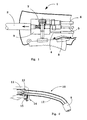
- figure 1 One of these known solutions is schematically illustrated in figure 1, in which number 1 indicates the torch body; pipe 2, connected to torch body 1, supplies wire and gas to the welding area.
- a block 3 made of metal such as brass; an electricity supply cable 4 and two pipes 5 and 6, which supply welding wire and gas respectively, are connected to the said block.
- Block 3 contains a valve 7 which moves between a lowered position in which it closes the gas supply and opens the electrical contact 8 and a raised position illustrated in figure 1 in which it closes the electricity supply contact and opens the gas supply, allowing the fluid to flow along pipe 2 which also supplies the welding wire.
- Torches have also been designed which are similar to the one described above, but with a plastic block.
- this system offers low resistance to mechanical stresses, with the result that the threaded part with the gas and wire supply connectors is weakened; the electricity supply cable must also bypass this block and be connected to pipe 2 downstream of the block in order to achieve the necessary electrical continuity, as plastic, of which the block is made, is an insulating material.
- no. 10 indicates the torch body assembly, which comprises a handgrip 11 and a torch body 12 basically constituted by a metal tubular element with a connector or union 13 on one side for connection to the welding wire and electricity supply pipes, and a nozzle 9 on the other side.
- Connector 13 designed for connection to the welding wire and electricity supply, is of known type, and will therefore not be illustrated in detail.
- a characteristic feature of the invention is that it includes a valve, indicated as 14, downstream of the said connector 13; the said valve contains a threaded hole 15 for connection to a gas supply pipe, and is fitted to the wall of torch body 12, downstream of connector 13.
- Valve 14 (fig. 3) comprises a body 16 which may, for example, be basically cylindrical; a connector 17 used to fit valve body 16 to torch body 12 is screwed into an axial hole (30) in the said valve body.
- This axial hole (30) communicates with threaded hole 15 through which gas is supplied from a pipe 24, the end of which is screwed to the thread of hole 15.
- Connector 17 has a central hole which places the interior of valve body 16 in communication with the torch body.
- valve body 16 presents a step 18 which divides the axial hole into two areas of different diameters, the lower area having the smaller diameter.
- a piston 19 slides in the part of body 16 with the smaller diameter; the said piston is fitted with a pair of O-ring seals 25 and can travel between the position illustrated in figure 3, in which the said O-rings cut off the gas flow aperture, and the raised position shown in figure 4, in which they open the said aperture, allowing the gas to flow into the valve pipe and then pass into torch body 12.
- a helical spring 20 or the like normally maintains piston 19, which acts as the valve plug, in the closed position, preventing gas from escaping from the ring-shaped chamber formed between this piston and the inner wall of valve body 16.
- piston 19 normally projects from body 16 and is driven by the torch activation button, which first pushes the piston upwards, and then closes the electricity supply contacts.
- the mechanism operates as follows: in the rest position, spring 20 pushes piston 19 downwards, until lower shoulder 22 comes to rest against circular rim 23 of body 16.
- the small amount of gas remaining in pipe 12 continues to insulate the area around the weld to guarantee a perfect, defect-free result.
Landscapes
- Engineering & Computer Science (AREA)
- Physics & Mathematics (AREA)
- Plasma & Fusion (AREA)
- Mechanical Engineering (AREA)
- Arc Welding In General (AREA)
- Feeding And Controlling Fuel (AREA)
- Lift Valve (AREA)
Claims (3)
- Schweißbrenner des Typs mit einem Gasversorgungssteuerventil (14), das mit einem Gasversorgungsrohr (24) verbunden ist,
dadurch gekennzeichnet dass das Ventil ein Nadelventil ist, das durch den Brennerknopf aktiviert wird, wobei das Ventil an der Wand des Brennerkörpers (12) unterstromig der Elektrizitäts- und Schweißdrahtversorgungsverbinder vorgesehen ist. - Schweißbrenner nach Anspruch 1,
wobei der Brennerknopf das Ventil öffnet und nachfolgend den Elektrizitätsversorgungskontakt schließt. - Schweißbrenner nach Anspruch 1,
dadurch gekennzeichnet, dass das Ventil umfasst:einen Körper (16) mit einem axialen Loch (30), wobei der Ventilkörper (16) an der Seite des Brennerkörpers (12) vorgesehen ist und mit dem Innenraum des Brennerkörpers in Verbindung steht;einen Kolben (19), der in dem axialen Loch (30) gleitet und eine ringförmige Nut aufweist, die eine ringförmige Kammer innerhalb des Loches bildet, wobei der Kolben derart ausgebildet ist, um zwischen einer ersten Position, in der er teilweise von dem Körper (16) vorragt, und einer zweiten Position bewegbar zu sein, in der er vollständig in den Körper zurückgezogen ist, wobei der Körper mit einem Verbinder für ein Gasversorgungsrohr (24) ausgerüstet ist, das zu der ringförmigen Kammer führt, die durch den Kolben ausgebildet ist,ein Mittel (20), das den Kolben in die Position drückt, in der dieser teilweise von dem Körper des Ventils vorragt;wobei das axiale Loch (30) in dem Ventilkörper zwei Bereiche mit unterschiedlichen Durchmessern aufweist; wobei die ringförmige Kammer, die durch den Kolben gebildet ist, an dem oberen und unteren Bereich durch Dichtungen (25) begrenzt ist, die zusammen mit dem Kolben gleiten und sich von (i) einer Position, in der sie beide eine Dichtung gegen die Wände des axialen Rohres (30) bilden, wenn sich der Kolben (19) in der Position befindet, in der er von dem Ventilkörper (16) vorragt, zu (ii) einer zweiten Position bewegen, in der sich eine der Dichtungen zu dem Abschnitt mit größeren Durchmesser des axialen Rohres bewegt, um die Öffnung zwischen der ringformigen Kammer und dem axialen Rohr zu öffnen, das dieses mit dem Innenraum des Brennerkörpers verbindet.
Applications Claiming Priority (3)
| Application Number | Priority Date | Filing Date | Title |
|---|---|---|---|
| ITVI980031U | 1998-04-15 | ||
| IT1998VI000031U IT245431Y1 (it) | 1998-04-15 | 1998-04-15 | Torcia di saldatura con valvola di controllo dell'alimentazione delgas applicata alla parete della torcia, a valle dell'attacco dell'ali |
| ITVI980031 | 1998-04-15 |
Publications (3)
| Publication Number | Publication Date |
|---|---|
| EP0950459A2 EP0950459A2 (de) | 1999-10-20 |
| EP0950459A3 EP0950459A3 (de) | 2000-05-10 |
| EP0950459B1 true EP0950459B1 (de) | 2003-06-04 |
Family
ID=11426592
Family Applications (1)
| Application Number | Title | Priority Date | Filing Date |
|---|---|---|---|
| EP99107166A Expired - Lifetime EP0950459B1 (de) | 1998-04-15 | 1999-04-13 | Schweissbrenner mit einem an der Brennerwand eingebauten Gasversorgungssteuerventil stromabwärts des Elektrizitätsversorgungssteckers |
Country Status (5)
| Country | Link |
|---|---|
| EP (1) | EP0950459B1 (de) |
| AT (1) | ATE242076T1 (de) |
| DE (1) | DE69908479T2 (de) |
| ES (1) | ES2201590T3 (de) |
| IT (1) | IT245431Y1 (de) |
Families Citing this family (1)
| Publication number | Priority date | Publication date | Assignee | Title |
|---|---|---|---|---|
| CN117167746B (zh) * | 2023-10-17 | 2024-05-14 | 徐州燃烧控制研究院有限公司 | 一种火炬系统余热回收用烟气处理设备及方法 |
Family Cites Families (3)
| Publication number | Priority date | Publication date | Assignee | Title |
|---|---|---|---|---|
| US3557337A (en) * | 1969-02-27 | 1971-01-19 | Air Prod & Chem | Welding torch |
| SE8802291L (sv) * | 1988-06-17 | 1989-12-18 | Esab Ab | Anordning foer tryckgasrensning av ett gasmunstycke vid en svetspistol |
| DE19619693C2 (de) * | 1995-05-19 | 2002-03-21 | Exedy Corp | Schutzgas-Schweißgerät |
-
1998
- 1998-04-15 IT IT1998VI000031U patent/IT245431Y1/it active
-
1999
- 1999-04-13 ES ES99107166T patent/ES2201590T3/es not_active Expired - Lifetime
- 1999-04-13 AT AT99107166T patent/ATE242076T1/de active
- 1999-04-13 DE DE69908479T patent/DE69908479T2/de not_active Expired - Lifetime
- 1999-04-13 EP EP99107166A patent/EP0950459B1/de not_active Expired - Lifetime
Also Published As
| Publication number | Publication date |
|---|---|
| ATE242076T1 (de) | 2003-06-15 |
| EP0950459A3 (de) | 2000-05-10 |
| ES2201590T3 (es) | 2004-03-16 |
| DE69908479D1 (de) | 2003-07-10 |
| EP0950459A2 (de) | 1999-10-20 |
| IT245431Y1 (it) | 2002-03-20 |
| DE69908479T2 (de) | 2004-04-29 |
| ITVI980031U1 (it) | 1999-10-15 |
Similar Documents
| Publication | Publication Date | Title |
|---|---|---|
| KR100207162B1 (ko) | 액화가스 키친 라이터 | |
| EP0515693B1 (de) | Zündanlage | |
| US4731518A (en) | Gun and cable for gas metal arc welding | |
| KR950007388B1 (ko) | 버너 장치 | |
| JPH0338952B2 (de) | ||
| WO1994012818B1 (en) | Fire control valve with replaceable locking pin assembly | |
| DE239546T1 (de) | Plasmabogenschneid- und -schweissbrenner fuer uebertragenen und nicht-uebertragenen bogenbetrieb. | |
| US20020098455A1 (en) | Gas control assembly | |
| US2310164A (en) | Electrode holder | |
| US6089856A (en) | Pilot control assembly | |
| EP0950459A2 (de) | Schweissbrenner mit einem an dem Brennerwand eingebauten Gasversorgungssteuerventil stromabwärts des Elektrizitätsversorgungsstecker | |
| US2935312A (en) | Apparatus for post-heating with a shielded arc spotwelding gun | |
| FR2574614A1 (fr) | Procede et dispositif de formation d'un arc plasma | |
| CN1146388A (zh) | 电焊弧的点火方法 | |
| US6884958B2 (en) | Welding torch having integral collet and collet body and method of operating same | |
| KR100912222B1 (ko) | 히팅기능을 갖춘 용접기용 가스절감밸브 어셈블리 | |
| US4973809A (en) | Cutting and gouging electrode | |
| JPS6156386B2 (de) | ||
| US4309588A (en) | Air cooled gas shielded arc torch | |
| US2783360A (en) | Welding torch | |
| CA2029508C (fr) | Torche a plasma pourvue d'une bobine electro-magnetique de rotation de pieds d'arc | |
| KR100896701B1 (ko) | 용접기용 가스절감밸브 어셈블리 | |
| JPS61501666A (ja) | 水銀スイッチ | |
| US4098309A (en) | Fuel container with filling valve | |
| JPS6014261B2 (ja) | 火口 |
Legal Events
| Date | Code | Title | Description |
|---|---|---|---|
| PUAI | Public reference made under article 153(3) epc to a published international application that has entered the european phase |
Free format text: ORIGINAL CODE: 0009012 |
|
| AK | Designated contracting states |
Kind code of ref document: A2 Designated state(s): AT BE CH DE DK ES FR GB IT LI NL SE |
|
| AX | Request for extension of the european patent |
Free format text: AL;LT;LV;MK;RO;SI |
|
| PUAL | Search report despatched |
Free format text: ORIGINAL CODE: 0009013 |
|
| AK | Designated contracting states |
Kind code of ref document: A3 Designated state(s): AT BE CH CY DE DK ES FI FR GB GR IE IT LI LU MC NL PT SE |
|
| AX | Request for extension of the european patent |
Free format text: AL;LT;LV;MK;RO;SI |
|
| 17P | Request for examination filed |
Effective date: 20001004 |
|
| AKX | Designation fees paid |
Free format text: AT BE CH DE DK ES FR GB IT LI NL SE |
|
| 17Q | First examination report despatched |
Effective date: 20020524 |
|
| GRAH | Despatch of communication of intention to grant a patent |
Free format text: ORIGINAL CODE: EPIDOS IGRA |
|
| GRAH | Despatch of communication of intention to grant a patent |
Free format text: ORIGINAL CODE: EPIDOS IGRA |
|
| GRAA | (expected) grant |
Free format text: ORIGINAL CODE: 0009210 |
|
| AK | Designated contracting states |
Designated state(s): AT BE CH DE DK ES FR GB IT LI NL SE |
|
| PG25 | Lapsed in a contracting state [announced via postgrant information from national office to epo] |
Ref country code: BE Free format text: LAPSE BECAUSE OF FAILURE TO SUBMIT A TRANSLATION OF THE DESCRIPTION OR TO PAY THE FEE WITHIN THE PRESCRIBED TIME-LIMIT Effective date: 20030604 |
|
| REG | Reference to a national code |
Ref country code: GB Ref legal event code: FG4D |
|
| REG | Reference to a national code |
Ref country code: CH Ref legal event code: EP |
|
| REF | Corresponds to: |
Ref document number: 69908479 Country of ref document: DE Date of ref document: 20030710 Kind code of ref document: P |
|
| PG25 | Lapsed in a contracting state [announced via postgrant information from national office to epo] |
Ref country code: DK Free format text: LAPSE BECAUSE OF FAILURE TO SUBMIT A TRANSLATION OF THE DESCRIPTION OR TO PAY THE FEE WITHIN THE PRESCRIBED TIME-LIMIT Effective date: 20030904 |
|
| REG | Reference to a national code |
Ref country code: SE Ref legal event code: TRGR |
|
| REG | Reference to a national code |
Ref country code: CH Ref legal event code: NV Representative=s name: AMMANN PATENTANWAELTE AG BERN |
|
| REG | Reference to a national code |
Ref country code: ES Ref legal event code: FG2A Ref document number: 2201590 Country of ref document: ES Kind code of ref document: T3 |
|
| ET | Fr: translation filed | ||
| PLBE | No opposition filed within time limit |
Free format text: ORIGINAL CODE: 0009261 |
|
| STAA | Information on the status of an ep patent application or granted ep patent |
Free format text: STATUS: NO OPPOSITION FILED WITHIN TIME LIMIT |
|
| 26N | No opposition filed |
Effective date: 20040305 |
|
| PGFP | Annual fee paid to national office [announced via postgrant information from national office to epo] |
Ref country code: NL Payment date: 20120413 Year of fee payment: 14 Ref country code: CH Payment date: 20120412 Year of fee payment: 14 Ref country code: DE Payment date: 20120425 Year of fee payment: 14 |
|
| PGFP | Annual fee paid to national office [announced via postgrant information from national office to epo] |
Ref country code: GB Payment date: 20120411 Year of fee payment: 14 Ref country code: SE Payment date: 20120411 Year of fee payment: 14 Ref country code: FR Payment date: 20120504 Year of fee payment: 14 |
|
| PGFP | Annual fee paid to national office [announced via postgrant information from national office to epo] |
Ref country code: IT Payment date: 20120419 Year of fee payment: 14 |
|
| PGFP | Annual fee paid to national office [announced via postgrant information from national office to epo] |
Ref country code: ES Payment date: 20120510 Year of fee payment: 14 |
|
| PGFP | Annual fee paid to national office [announced via postgrant information from national office to epo] |
Ref country code: AT Payment date: 20120327 Year of fee payment: 14 |
|
| REG | Reference to a national code |
Ref country code: NL Ref legal event code: V1 Effective date: 20131101 |
|
| REG | Reference to a national code |
Ref country code: CH Ref legal event code: PL |
|
| REG | Reference to a national code |
Ref country code: SE Ref legal event code: EUG |
|
| REG | Reference to a national code |
Ref country code: AT Ref legal event code: MM01 Ref document number: 242076 Country of ref document: AT Kind code of ref document: T Effective date: 20130430 |
|
| GBPC | Gb: european patent ceased through non-payment of renewal fee |
Effective date: 20130413 |
|
| PG25 | Lapsed in a contracting state [announced via postgrant information from national office to epo] |
Ref country code: AT Free format text: LAPSE BECAUSE OF NON-PAYMENT OF DUE FEES Effective date: 20130430 Ref country code: SE Free format text: LAPSE BECAUSE OF NON-PAYMENT OF DUE FEES Effective date: 20130414 Ref country code: CH Free format text: LAPSE BECAUSE OF NON-PAYMENT OF DUE FEES Effective date: 20130430 Ref country code: GB Free format text: LAPSE BECAUSE OF NON-PAYMENT OF DUE FEES Effective date: 20130413 Ref country code: DE Free format text: LAPSE BECAUSE OF NON-PAYMENT OF DUE FEES Effective date: 20131101 Ref country code: LI Free format text: LAPSE BECAUSE OF NON-PAYMENT OF DUE FEES Effective date: 20130430 |
|
| REG | Reference to a national code |
Ref country code: FR Ref legal event code: ST Effective date: 20131231 |
|
| REG | Reference to a national code |
Ref country code: DE Ref legal event code: R119 Ref document number: 69908479 Country of ref document: DE Effective date: 20131101 |
|
| PG25 | Lapsed in a contracting state [announced via postgrant information from national office to epo] |
Ref country code: FR Free format text: LAPSE BECAUSE OF NON-PAYMENT OF DUE FEES Effective date: 20130430 Ref country code: IT Free format text: LAPSE BECAUSE OF NON-PAYMENT OF DUE FEES Effective date: 20130413 Ref country code: NL Free format text: LAPSE BECAUSE OF NON-PAYMENT OF DUE FEES Effective date: 20131101 |
|
| REG | Reference to a national code |
Ref country code: ES Ref legal event code: FD2A Effective date: 20140606 |
|
| PG25 | Lapsed in a contracting state [announced via postgrant information from national office to epo] |
Ref country code: ES Free format text: LAPSE BECAUSE OF NON-PAYMENT OF DUE FEES Effective date: 20130414 |