EP0950431A2 - Mit festen ionenleitenden Elektrolyt versehende Anordnung - Google Patents
Mit festen ionenleitenden Elektrolyt versehende Anordnung Download PDFInfo
- Publication number
- EP0950431A2 EP0950431A2 EP99107669A EP99107669A EP0950431A2 EP 0950431 A2 EP0950431 A2 EP 0950431A2 EP 99107669 A EP99107669 A EP 99107669A EP 99107669 A EP99107669 A EP 99107669A EP 0950431 A2 EP0950431 A2 EP 0950431A2
- Authority
- EP
- European Patent Office
- Prior art keywords
- gas flow
- stack
- layers
- flow path
- electrodes
- Prior art date
- Legal status (The legal status is an assumption and is not a legal conclusion. Google has not performed a legal analysis and makes no representation as to the accuracy of the status listed.)
- Granted
Links
- 239000007784 solid electrolyte Substances 0.000 title 1
- 239000012528 membrane Substances 0.000 claims abstract description 32
- 239000003792 electrolyte Substances 0.000 claims abstract description 29
- 239000007789 gas Substances 0.000 claims description 115
- 239000001301 oxygen Substances 0.000 claims description 36
- 229910052760 oxygen Inorganic materials 0.000 claims description 36
- QVGXLLKOCUKJST-UHFFFAOYSA-N atomic oxygen Chemical compound [O] QVGXLLKOCUKJST-UHFFFAOYSA-N 0.000 claims description 34
- 238000000034 method Methods 0.000 claims description 7
- 239000004020 conductor Substances 0.000 claims description 5
- 239000000446 fuel Substances 0.000 claims description 5
- 239000002737 fuel gas Substances 0.000 claims description 3
- 150000002500 ions Chemical class 0.000 claims description 2
- 238000012546 transfer Methods 0.000 claims description 2
- 239000010410 layer Substances 0.000 description 66
- 238000010276 construction Methods 0.000 description 11
- 239000000463 material Substances 0.000 description 4
- 238000004891 communication Methods 0.000 description 3
- 238000007789 sealing Methods 0.000 description 3
- MYMOFIZGZYHOMD-UHFFFAOYSA-N Dioxygen Chemical compound O=O MYMOFIZGZYHOMD-UHFFFAOYSA-N 0.000 description 2
- 239000000919 ceramic Substances 0.000 description 2
- 229910001882 dioxygen Inorganic materials 0.000 description 2
- 239000001257 hydrogen Substances 0.000 description 2
- 229910052739 hydrogen Inorganic materials 0.000 description 2
- 125000004435 hydrogen atom Chemical class [H]* 0.000 description 2
- 238000004519 manufacturing process Methods 0.000 description 2
- -1 oxygen anions Chemical class 0.000 description 2
- 229910052709 silver Inorganic materials 0.000 description 2
- 239000004332 silver Substances 0.000 description 2
- QBYHSJRFOXINMH-UHFFFAOYSA-N [Co].[Sr].[La] Chemical compound [Co].[Sr].[La] QBYHSJRFOXINMH-UHFFFAOYSA-N 0.000 description 1
- 229910045601 alloy Inorganic materials 0.000 description 1
- 239000000956 alloy Substances 0.000 description 1
- QAISYPNSOYCTPY-UHFFFAOYSA-N cerium(3+) gadolinium(3+) oxygen(2-) Chemical compound [O--].[O--].[O--].[Ce+3].[Gd+3] QAISYPNSOYCTPY-UHFFFAOYSA-N 0.000 description 1
- 238000000151 deposition Methods 0.000 description 1
- 238000013461 design Methods 0.000 description 1
- 238000009792 diffusion process Methods 0.000 description 1
- 239000007772 electrode material Substances 0.000 description 1
- 238000012986 modification Methods 0.000 description 1
- 230000004048 modification Effects 0.000 description 1
- 239000002356 single layer Substances 0.000 description 1
- 229910000859 α-Fe Inorganic materials 0.000 description 1
Images
Classifications
-
- H—ELECTRICITY
- H01—ELECTRIC ELEMENTS
- H01M—PROCESSES OR MEANS, e.g. BATTERIES, FOR THE DIRECT CONVERSION OF CHEMICAL ENERGY INTO ELECTRICAL ENERGY
- H01M8/00—Fuel cells; Manufacture thereof
- H01M8/24—Grouping of fuel cells, e.g. stacking of fuel cells
- H01M8/241—Grouping of fuel cells, e.g. stacking of fuel cells with solid or matrix-supported electrolytes
-
- B—PERFORMING OPERATIONS; TRANSPORTING
- B01—PHYSICAL OR CHEMICAL PROCESSES OR APPARATUS IN GENERAL
- B01D—SEPARATION
- B01D53/00—Separation of gases or vapours; Recovering vapours of volatile solvents from gases; Chemical or biological purification of waste gases, e.g. engine exhaust gases, smoke, fumes, flue gases, aerosols
- B01D53/32—Separation of gases or vapours; Recovering vapours of volatile solvents from gases; Chemical or biological purification of waste gases, e.g. engine exhaust gases, smoke, fumes, flue gases, aerosols by electrical effects other than those provided for in group B01D61/00
- B01D53/326—Separation of gases or vapours; Recovering vapours of volatile solvents from gases; Chemical or biological purification of waste gases, e.g. engine exhaust gases, smoke, fumes, flue gases, aerosols by electrical effects other than those provided for in group B01D61/00 in electrochemical cells
-
- B—PERFORMING OPERATIONS; TRANSPORTING
- B01—PHYSICAL OR CHEMICAL PROCESSES OR APPARATUS IN GENERAL
- B01J—CHEMICAL OR PHYSICAL PROCESSES, e.g. CATALYSIS OR COLLOID CHEMISTRY; THEIR RELEVANT APPARATUS
- B01J19/00—Chemical, physical or physico-chemical processes in general; Their relevant apparatus
- B01J19/24—Stationary reactors without moving elements inside
- B01J19/248—Reactors comprising multiple separated flow channels
- B01J19/249—Plate-type reactors
-
- C—CHEMISTRY; METALLURGY
- C01—INORGANIC CHEMISTRY
- C01B—NON-METALLIC ELEMENTS; COMPOUNDS THEREOF; METALLOIDS OR COMPOUNDS THEREOF NOT COVERED BY SUBCLASS C01C
- C01B13/00—Oxygen; Ozone; Oxides or hydroxides in general
- C01B13/02—Preparation of oxygen
- C01B13/0229—Purification or separation processes
- C01B13/0248—Physical processing only
- C01B13/0251—Physical processing only by making use of membranes
-
- C—CHEMISTRY; METALLURGY
- C25—ELECTROLYTIC OR ELECTROPHORETIC PROCESSES; APPARATUS THEREFOR
- C25B—ELECTROLYTIC OR ELECTROPHORETIC PROCESSES FOR THE PRODUCTION OF COMPOUNDS OR NON-METALS; APPARATUS THEREFOR
- C25B15/00—Operating or servicing cells
- C25B15/08—Supplying or removing reactants or electrolytes; Regeneration of electrolytes
-
- C—CHEMISTRY; METALLURGY
- C25—ELECTROLYTIC OR ELECTROPHORETIC PROCESSES; APPARATUS THEREFOR
- C25B—ELECTROLYTIC OR ELECTROPHORETIC PROCESSES FOR THE PRODUCTION OF COMPOUNDS OR NON-METALS; APPARATUS THEREFOR
- C25B9/00—Cells or assemblies of cells; Constructional parts of cells; Assemblies of constructional parts, e.g. electrode-diaphragm assemblies; Process-related cell features
- C25B9/70—Assemblies comprising two or more cells
-
- H—ELECTRICITY
- H01—ELECTRIC ELEMENTS
- H01M—PROCESSES OR MEANS, e.g. BATTERIES, FOR THE DIRECT CONVERSION OF CHEMICAL ENERGY INTO ELECTRICAL ENERGY
- H01M8/00—Fuel cells; Manufacture thereof
- H01M8/02—Details
- H01M8/0271—Sealing or supporting means around electrodes, matrices or membranes
-
- H—ELECTRICITY
- H01—ELECTRIC ELEMENTS
- H01M—PROCESSES OR MEANS, e.g. BATTERIES, FOR THE DIRECT CONVERSION OF CHEMICAL ENERGY INTO ELECTRICAL ENERGY
- H01M8/00—Fuel cells; Manufacture thereof
- H01M8/24—Grouping of fuel cells, e.g. stacking of fuel cells
- H01M8/241—Grouping of fuel cells, e.g. stacking of fuel cells with solid or matrix-supported electrolytes
- H01M8/2425—High-temperature cells with solid electrolytes
- H01M8/2432—Grouping of unit cells of planar configuration
-
- H—ELECTRICITY
- H01—ELECTRIC ELEMENTS
- H01M—PROCESSES OR MEANS, e.g. BATTERIES, FOR THE DIRECT CONVERSION OF CHEMICAL ENERGY INTO ELECTRICAL ENERGY
- H01M8/00—Fuel cells; Manufacture thereof
- H01M8/24—Grouping of fuel cells, e.g. stacking of fuel cells
- H01M8/2465—Details of groupings of fuel cells
- H01M8/2483—Details of groupings of fuel cells characterised by internal manifolds
-
- B—PERFORMING OPERATIONS; TRANSPORTING
- B01—PHYSICAL OR CHEMICAL PROCESSES OR APPARATUS IN GENERAL
- B01J—CHEMICAL OR PHYSICAL PROCESSES, e.g. CATALYSIS OR COLLOID CHEMISTRY; THEIR RELEVANT APPARATUS
- B01J2219/00—Chemical, physical or physico-chemical processes in general; Their relevant apparatus
- B01J2219/24—Stationary reactors without moving elements inside
- B01J2219/2401—Reactors comprising multiple separate flow channels
- B01J2219/245—Plate-type reactors
- B01J2219/2451—Geometry of the reactor
- B01J2219/2453—Plates arranged in parallel
-
- B—PERFORMING OPERATIONS; TRANSPORTING
- B01—PHYSICAL OR CHEMICAL PROCESSES OR APPARATUS IN GENERAL
- B01J—CHEMICAL OR PHYSICAL PROCESSES, e.g. CATALYSIS OR COLLOID CHEMISTRY; THEIR RELEVANT APPARATUS
- B01J2219/00—Chemical, physical or physico-chemical processes in general; Their relevant apparatus
- B01J2219/24—Stationary reactors without moving elements inside
- B01J2219/2401—Reactors comprising multiple separate flow channels
- B01J2219/245—Plate-type reactors
- B01J2219/2475—Separation means, e.g. membranes inside the reactor
-
- B—PERFORMING OPERATIONS; TRANSPORTING
- B01—PHYSICAL OR CHEMICAL PROCESSES OR APPARATUS IN GENERAL
- B01J—CHEMICAL OR PHYSICAL PROCESSES, e.g. CATALYSIS OR COLLOID CHEMISTRY; THEIR RELEVANT APPARATUS
- B01J2219/00—Chemical, physical or physico-chemical processes in general; Their relevant apparatus
- B01J2219/24—Stationary reactors without moving elements inside
- B01J2219/2401—Reactors comprising multiple separate flow channels
- B01J2219/245—Plate-type reactors
- B01J2219/2476—Construction materials
- B01J2219/2477—Construction materials of the catalysts
- B01J2219/2479—Catalysts coated on the surface of plates or inserts
-
- B—PERFORMING OPERATIONS; TRANSPORTING
- B01—PHYSICAL OR CHEMICAL PROCESSES OR APPARATUS IN GENERAL
- B01J—CHEMICAL OR PHYSICAL PROCESSES, e.g. CATALYSIS OR COLLOID CHEMISTRY; THEIR RELEVANT APPARATUS
- B01J2219/00—Chemical, physical or physico-chemical processes in general; Their relevant apparatus
- B01J2219/24—Stationary reactors without moving elements inside
- B01J2219/2401—Reactors comprising multiple separate flow channels
- B01J2219/245—Plate-type reactors
- B01J2219/2476—Construction materials
- B01J2219/2477—Construction materials of the catalysts
- B01J2219/2482—Catalytically active foils; Plates having catalytically activity on their own
-
- B—PERFORMING OPERATIONS; TRANSPORTING
- B01—PHYSICAL OR CHEMICAL PROCESSES OR APPARATUS IN GENERAL
- B01J—CHEMICAL OR PHYSICAL PROCESSES, e.g. CATALYSIS OR COLLOID CHEMISTRY; THEIR RELEVANT APPARATUS
- B01J2219/00—Chemical, physical or physico-chemical processes in general; Their relevant apparatus
- B01J2219/24—Stationary reactors without moving elements inside
- B01J2219/2401—Reactors comprising multiple separate flow channels
- B01J2219/245—Plate-type reactors
- B01J2219/2476—Construction materials
- B01J2219/2483—Construction materials of the plates
- B01J2219/2485—Metals or alloys
-
- B—PERFORMING OPERATIONS; TRANSPORTING
- B01—PHYSICAL OR CHEMICAL PROCESSES OR APPARATUS IN GENERAL
- B01J—CHEMICAL OR PHYSICAL PROCESSES, e.g. CATALYSIS OR COLLOID CHEMISTRY; THEIR RELEVANT APPARATUS
- B01J2219/00—Chemical, physical or physico-chemical processes in general; Their relevant apparatus
- B01J2219/24—Stationary reactors without moving elements inside
- B01J2219/2401—Reactors comprising multiple separate flow channels
- B01J2219/245—Plate-type reactors
- B01J2219/2476—Construction materials
- B01J2219/2483—Construction materials of the plates
- B01J2219/2487—Ceramics
-
- B—PERFORMING OPERATIONS; TRANSPORTING
- B01—PHYSICAL OR CHEMICAL PROCESSES OR APPARATUS IN GENERAL
- B01J—CHEMICAL OR PHYSICAL PROCESSES, e.g. CATALYSIS OR COLLOID CHEMISTRY; THEIR RELEVANT APPARATUS
- B01J2219/00—Chemical, physical or physico-chemical processes in general; Their relevant apparatus
- B01J2219/24—Stationary reactors without moving elements inside
- B01J2219/2401—Reactors comprising multiple separate flow channels
- B01J2219/245—Plate-type reactors
- B01J2219/2476—Construction materials
- B01J2219/2483—Construction materials of the plates
- B01J2219/2488—Glass
-
- B—PERFORMING OPERATIONS; TRANSPORTING
- B01—PHYSICAL OR CHEMICAL PROCESSES OR APPARATUS IN GENERAL
- B01J—CHEMICAL OR PHYSICAL PROCESSES, e.g. CATALYSIS OR COLLOID CHEMISTRY; THEIR RELEVANT APPARATUS
- B01J2219/00—Chemical, physical or physico-chemical processes in general; Their relevant apparatus
- B01J2219/24—Stationary reactors without moving elements inside
- B01J2219/2401—Reactors comprising multiple separate flow channels
- B01J2219/245—Plate-type reactors
- B01J2219/2491—Other constructional details
- B01J2219/2492—Assembling means
- B01J2219/2493—Means for assembling plates together, e.g. sealing means, screws, bolts
-
- C—CHEMISTRY; METALLURGY
- C01—INORGANIC CHEMISTRY
- C01B—NON-METALLIC ELEMENTS; COMPOUNDS THEREOF; METALLOIDS OR COMPOUNDS THEREOF NOT COVERED BY SUBCLASS C01C
- C01B2210/00—Purification or separation of specific gases
- C01B2210/0043—Impurity removed
- C01B2210/0046—Nitrogen
-
- Y—GENERAL TAGGING OF NEW TECHNOLOGICAL DEVELOPMENTS; GENERAL TAGGING OF CROSS-SECTIONAL TECHNOLOGIES SPANNING OVER SEVERAL SECTIONS OF THE IPC; TECHNICAL SUBJECTS COVERED BY FORMER USPC CROSS-REFERENCE ART COLLECTIONS [XRACs] AND DIGESTS
- Y02—TECHNOLOGIES OR APPLICATIONS FOR MITIGATION OR ADAPTATION AGAINST CLIMATE CHANGE
- Y02E—REDUCTION OF GREENHOUSE GAS [GHG] EMISSIONS, RELATED TO ENERGY GENERATION, TRANSMISSION OR DISTRIBUTION
- Y02E60/00—Enabling technologies; Technologies with a potential or indirect contribution to GHG emissions mitigation
- Y02E60/30—Hydrogen technology
- Y02E60/50—Fuel cells
Definitions
- This invention relates to an ionic conduction device which may be used for examples only, as an oxygen generating device or as a fuel cell.
- Such devices comprise a stack of layers, each layer comprising a membrane of a suitable electrolyte, having a pair of opposed surfaces with an electrode in contact with each opposed surface.
- Such layers are also known as tri-layers by virtue of their three main component construction.
- the layers are conventionally separated by interconnects which also provide for gas flow throughout the device, and electrical continuity throughout the device.
- the interconnects may provide for an air flow from a plenum along one side of the stack, over one of opposed faces of the layers, oxygen passing through the layers to the other of the opposed faces of the layers, the oxygen depleted gas being collected in a plenum along another of the stack sides, whilst the oxygen generated at the other of the faces of the layers, being collected in another plenum along yet another side of the stack.
- Such devices are complex to make, requiring a large number of high quality components to be assembled. For example flatness of the components to a high degree is necessary for a satisfactory device to be provided.
- an ionic conduction device comprising a stack of layers, each layer comprising an electrolyte membrane having a pair of opposed surfaces, a gas permeable electrode in contact with each opposed surface, and there being a plurality of interconnects in electrical contact with the electrodes of the layers, to provide electrical continuity through the stack, characterised in that there is at least one gas flow path though the layers and the interconnects of the stack.
- gas flow is through the layers and interconnects of the stack rather than though the stack to and from plenems along the sides of the stack. This considerably facilitates manufacture and construction and thus results in a substantial cost saving.
- the gas flow path through the layers and interconnects is provided by passage means, the passage means opening at one face of the layer into a space between the layer and the adjacent interconnect, and the passage means extending from a second face of the layer to the next adjacent interconnect.
- first and second faces of the layers there may be provided between the interconnects and the layers at the first and second faces of the layers, spaces, there being a first gas flow path through the layers and interconnects of the stack which permits of gas flow through the stack, and the first gas flow path communicating with the spaces at the first of the opposed faces of the layers, and a second gas flow path through the layers and interconnects of the stack which permits of gas flow through the stack, and the second gas flow path communicating with the spaces at the second of the opposed faces of the layers.
- first and second gas flow paths may be kept physically separate from one another whilst ions of gas may pass through the electrolyte membrane to provide for gas transfer from one of the gas flow paths to the other.
- the device may be used as either an oxygen generating device or a fuel cell, for examples only.
- a third gas flow path through the layers and interconnects of the stack, the third gas flow path communicating with the spaces at the first of the opposed faces of the layers.
- the first gas flow path may be for air, and the second gas flow path for the generated oxygen.
- the third gas flow path where provided, may be for oxygen depleted air.
- the first gas flow path may be for a fuel gas such as hydrogen
- the second gas flow path may be for a gas comprising oxygen
- the third gas flow path may be for exhaust gas.
- the passage means through the layers will necessarily comprise edges of the electrolyte membranes and electrodes.
- means may be provided to seal at least the edges of the electrodes in the passage means to prevent gas leakage from one gas flow path to the other.
- films of a conducting material which may serve to improve the electrical connection between the interconnects and the electrodes and facilitate gas sealing at that interface.
- the stack may comprise four sides, and first and second ends, the gas flow paths extending through the stack in a direction between the first and second ends thereof, and the first gas flow path though the stack may be provided adjacent one side of the stack, the second gas flow path adjacent a second side of the stack arid the third gas flow path, where provided, adjacent a third side of the stack.
- the layers may provide a stepped configuration with the electrolyte membrane extending outwardly at the side and/or inwardly of the gas flow path respectively, beyond the electrodes in contact with the opposed surfaces of the electrolyte membrane, and the electrodes may each extend outwardly at the side and/or inwardly of the gas flow path respectively, beyond the interconnects in electrical contact with the electrodes.
- the electrodes may extend outwardly at the side and/or inwardly of the gas flow path respectively, beyond the films, and the films may extend outwardly at the side and/or inwardly of the gas flow path respectively, beyond the interconnects.
- an ionic conduction device comprising at least one layer comprising an electrolyte membrane having a pair of opposed surfaces, a gas permeable electrode in contact with each opposed surface, and an interconnect in electrical contact with each of the electrodes, characterised in that at at least one of the sides of the stack the layer provides a stepped configuration with the electrolyte membrane extending outwardly beyond the electrodes in contact with the opposed surfaces of the electrolyte membrane, and the electrodes each extending outwardly beyond the interconnects in electrical contact with the electrodes.
- a third aspect of the invention we provide a method of operating an ionic conduction device comprising a stack of layers, each layer comprising an electrolyte membrane having a pair of opposed surfaces, a gas permeable electrode in contact with each opposed surface, and there being a plurality of interconnects in electrical contact with the electrodes of the layers to provide electrical continuity through the stack, the method comprising feeding gas to an end of the stack, and causing the gas to flow along the stack between the ends thereof.
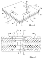
- FIG. 1 of the drawings there is shown an illustrative perspective view of part of an ionic conduction device 10 in accordance with the invention.
- the part of the device 10 shown comprises a single layers L1, commonly referred to as a tri-layer, comprising an electrolyte membrane 12 such as for example only, Cerium Gadolinium Oxide, and at each face of the membrane 12, there is provided in contact with the membrane an electrode 13, 14.
- the electrodes 13, 14 are gas porous for a purpose hereinafter explained.
- a plurality of such tri-layers L1 are in practice, arranged in a stack, with interconnects 15a, 15b etc. separating the layers in the stack.
- the interconnects may be metallic e.g. made of Haynes alloy 230), or another suitable material.
- the air is fed to each of the one faces 30 of each of the layers L1 simultaneously from an air source e.g. a plenum located at one side 19 of the stack.
- the oxygen depleted air is collected at another side 23 of the stack e.g. in a second plenum or is otherwise exhausted, and the oxygen is collected e.g. in another plenum at yet another side 21 of the stack.
- a gas flow path F1 is provided through the layers L1 of the stack, by passage means 18.
- Such passage means 18 may comprise one or more slots adjacent the one side 19 of the stack as shown in full lines in figure 1, or a plurality of smaller openings as indicated in dotted lines in figure 1.
- passage means 18 will extend throughout all or substantially all of the length of the stack from one end E1 to the opposite end E2 of the stack.
- a second gas flow path F2 is provided through the stack by a further passage means 20 which may again comprise one or more slots or a plurality of smaller openings, the passage means 20 again extending throughout all or substantially all the length of the stack, but adjacent the second side 21 of the stack.
- a third gas flow path F3 is provided through the stack by a yet further passage means 22 which may again comprise one or more slots or plurality of smaller openings, the passage means 22 again extending throughout all or substantially all the length of the stack, but adjacent the third side 23 of the stack.
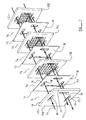
- the stack comprises in this example, three tri-layers L1, L2, L3 of electrolyte membrane and electrodes 13, 14, the layers L1-L3 being separated by and sandwiched between four interconnects 15a, 15b, 15c, 15d.
- the interconnect 15a By virtue of the construction of the interconnect 15a, there is provided a space S1 between the interconnect 15a and the first L1 of the three layers L1L3, at a first face 30 of the layer L1, which space S1 communicates with the first gas flow path F1 of air, and the third gas flow path F3 for oxygen depleted air. However, the construction of the interconnect 15a prevents communication between the space S1 and the second gas flow path F2.
- next interconnect 15b there is provided a space S2 at the opposite face 31 of the layer L1 which space S2 communicates with the second gas flow path F2 for the oxygen, only.
- the second interconnect 15b of the stack like the first interconnect 15a provides a space S3 between the second interconnect 15b and the second layer L2 which provides for communication between the first gas flow path F1 for the air, the space S3 and the third gas flow path F3 for the oxygen depleted air, and so on for all the interconnects 15a to 15d and tri-layers L1 to L3 of the stack.
- the device 10 is operated at an elevated temperature of typically 960°C and an electrical potential, of perhaps 100V, is applied from one end E1 of the stack to the other end E2.
- an electrical potential of perhaps 100V
- Figure 3 shows a cross sectional view through part of the passage means 18 of the device which provides the first gas flow path F1, although it will be appreciated that the passage means 20, 22 which provide the second F2 and third F3 flow paths may, be similarly constructed.
- each passage means 18 there is an edge of a further component being a current collector 35, 36, the purpose of which will be explained below.
- the gas is thus generally contrained to flow through the passage means 18 along axis A which is generally parallel the extent of the stack from end E1 to end E2.
- the electrode 13, 14 material is gas porous, there is the possibility of gas escaping from the passage means 18 through the electrodes 13, 14.
- Such gas escape is not critical where it is appropriate for the gas to be oil that particular side of the electrolyte membrane 12, for example in the case of the passage means 18, in space S1, or in the case of a passage means 22 for the oxygen depleted gas, in space S1, but for the oxygen flowing in a passage means 20, means may be provided to seal the edges of the electrodes 13, 14 or at least the flow path for the oxygen through the electrodes 13, 14 from the passage means 18 may be made as tortuous as possible to deter gas flow from the edges of the electrodes 13, 14.
- One or more of the sides 19 and/or 21 and/or 23 and or the remaining side of the stack may be constructed in a stepped configuration similarly to the stepped configuration within the passage means 18 shown and desribed with reference to figure 3, with the electrolyte membrane 12 of the or each of the layers extending outwardly beyond the electrodes 13, 14 in contact with the opposed surfaces of the electrolyte membrabe 12, and the electrodes 13, 14 extending outwardly beyond the current collector films 35, 36 where provided, and the films 35, 36, or at least the electrodes 13, 14 extending outwardly beyond the adjacent interconnects 15a, 15b.
- the need for the component parts of the device to be critically flat is less demanding as the current collector components 35, 36 function as gaskets between the electrodes 13, 14 and interconnects 15a, 15b to provide for good sealing between the two.
- the stepped configuration of the layers simplify the manufacture of the device 10 generally and eliminate any need to insulate the various layers against short circuits.
- the interconnects 15a to 15d will be appropriately shaped (i.e. cut away) at face 30 of the tri-layer L1 and at the other first faces of the other tri-layers L2, L3 which face in the same direction, around the opening, whilst the interconnects 15a to 15d will be shaped to prevent air from the opening flowing into the spaces S2, S4, S6 in which the oxygen collects.
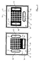
- FIG 4 there is a more detailed but still diagrammatic illustration of the alternative faces 30,31 of the L1 of the tri-layers L1 to L3.
- the electrolyte membrane L3 can be seen at the periphery of the layers L1 shown, and also in areas not covered with other components.
- the appropriate electrode 13, 14 On top of the electrolyte membrane 12 there is provided the appropriate electrode 13, 14.
- the electrodes 13, 14 may be deposited on the opposing surfaces of the membrane 12 by any suitable deposition technique, depending on the material from which the electrodes are made.
- the electrodes 13, 14 may be made of Lanthanum Strontium Cobalt Ferrite (LSCF) or another suitable material.
- LSCF Lanthanum Strontium Cobalt Ferrite
- a film of silver or another highly conductive material which films provide the current collectors 35, 36 described with reference to figure 3.
- the current collectors 35, 36 only partially cover the electrodes 13, 14 so as to permit of diffusion of the gas through the electrodes 13, 14, and in this example it can be seen that the current collectors 35, 36 form a criss-cross patters over the electrodes 13, 14.
- the actual number of tri-layers L1 to L3 will in practice usually be greater than three, the actual number depending on the design capacity of the device 10.
- the shapes of the passage means 18, 20, 22 may be different from that described and may depend on the cross sectional area for gas flow required through the device 10.
- the passage means 18 and/or 20 and/or 22 may vary in cross section throughout the length of the device, from end to end, if desired.
- the air, oxygen depleted air and the oxygen may be delivered to or collected from the same end E1 or E2 of the stack by one or more simply constructed and assembled manifolds or may be delivered to and collected from opposite ends E1/E2 or both ends of the stack, as desired.
- the invention has been described with reference particularly to an ionic conduction device for generating oxygen, it will be appreciated that a similar construction may provide a novel fuel cell construction having the advantages of the ceramic oxygen generator described.
- the first gas flow instead of air comprising the first gas flow F1, oxygen the second gas flow F2 and oxygen depleted air the third gas flow F3, the first gas flow may be fuel gas such as hydrogen, the second gas flow F2 may be for gas comprising oxygen, and the third gas flow F3 may be for exhaust gas.
- construction may, be utilised as an ionic conducting device for another use.
Landscapes
- Chemical & Material Sciences (AREA)
- Chemical Kinetics & Catalysis (AREA)
- Electrochemistry (AREA)
- Engineering & Computer Science (AREA)
- Organic Chemistry (AREA)
- General Chemical & Material Sciences (AREA)
- Manufacturing & Machinery (AREA)
- Life Sciences & Earth Sciences (AREA)
- Sustainable Development (AREA)
- Sustainable Energy (AREA)
- Analytical Chemistry (AREA)
- Materials Engineering (AREA)
- Metallurgy (AREA)
- Oil, Petroleum & Natural Gas (AREA)
- Inorganic Chemistry (AREA)
- Fuel Cell (AREA)
- Conductive Materials (AREA)
- Hybrid Cells (AREA)
Applications Claiming Priority (2)
| Application Number | Priority Date | Filing Date | Title |
|---|---|---|---|
| GB9808133 | 1998-04-18 | ||
| GBGB9808133.4A GB9808133D0 (en) | 1998-04-18 | 1998-04-18 | Ionic conduction device |
Publications (3)
| Publication Number | Publication Date |
|---|---|
| EP0950431A2 true EP0950431A2 (de) | 1999-10-20 |
| EP0950431A3 EP0950431A3 (de) | 2000-01-19 |
| EP0950431B1 EP0950431B1 (de) | 2005-03-16 |
Family
ID=10830474
Family Applications (1)
| Application Number | Title | Priority Date | Filing Date |
|---|---|---|---|
| EP99107669A Expired - Lifetime EP0950431B1 (de) | 1998-04-18 | 1999-04-16 | Mit festen ionenleitenden Elektrolyt versehende Anordnung |
Country Status (4)
| Country | Link |
|---|---|
| US (1) | US6203676B1 (de) |
| EP (1) | EP0950431B1 (de) |
| DE (1) | DE69924175T2 (de) |
| GB (1) | GB9808133D0 (de) |
Cited By (2)
| Publication number | Priority date | Publication date | Assignee | Title |
|---|---|---|---|---|
| EP1496560A1 (de) | 2003-07-04 | 2005-01-12 | Honeywell Normalair-Garrett (Holdings) Limited | Ionenleitende Anordnung |
| US7144649B2 (en) | 2002-11-27 | 2006-12-05 | Utc Fuel Cells, Llc | Interconnect for solid oxide fuel cells |
Families Citing this family (9)
| Publication number | Priority date | Publication date | Assignee | Title |
|---|---|---|---|---|
| AU2002368052A1 (en) * | 2001-06-29 | 2004-02-23 | Nextech Materials, Ltd. | Nano-composite electrodes and method of making the same |
| US6783646B2 (en) * | 2002-08-28 | 2004-08-31 | Carleton Life Support Systems, Inc. | Modular ceramic oxygen system |
| US6905581B2 (en) | 2002-10-31 | 2005-06-14 | Carleton Life Support Systems, Inc. | Oxygen permeable electrode system |
| US7449262B2 (en) * | 2004-12-09 | 2008-11-11 | Praxair Technology, Inc. | Current collector to conduct an electrical current to or from an electrode layer |
| US7752845B2 (en) | 2007-01-08 | 2010-07-13 | Robert Paul Johnson | Solar-powered, liquid-hydrocarbon-fuel synthesizer |
| BR112014031220A2 (pt) | 2012-06-12 | 2017-06-27 | Univ Monash | estrutura de eletrodo com capacidade de respiração e método e sistema para uso em separação da água |
| JP6267691B2 (ja) * | 2012-06-12 | 2018-01-24 | アクアハイドレックス プロプライエタリー リミテッドAquahydrex Pty Ltd | ガス透過性電極及び電気化学セル |
| AU2014295916A1 (en) | 2013-07-31 | 2016-02-11 | Aquahydrex Pty Ltd | Electro-synthetic or electro-energy cell with gas diffusion electrode(s) |
| KR20210122260A (ko) | 2019-02-01 | 2021-10-08 | 아쿠아하이드렉스, 인크. | 제한된 전해질을 갖춘 전기화학적 시스템 |
Family Cites Families (9)
| Publication number | Priority date | Publication date | Assignee | Title |
|---|---|---|---|---|
| US4629537A (en) * | 1985-05-17 | 1986-12-16 | Hsu Michael S | Compact, light-weight, solid-oxide electrochemical converter |
| DE4016157A1 (de) * | 1989-06-08 | 1990-12-13 | Asea Brown Boveri | Vorrichtung zur umwandlung von chemischer energie in elektrische energie mittels in serie geschalteter flacher, ebener hochtemperatur-brennstoffzellen |
| US5186806A (en) * | 1990-12-31 | 1993-02-16 | California Institute Of Technology | Ceramic distribution members for solid state electrolyte cells and method of producing |
| JP2966548B2 (ja) * | 1991-03-01 | 1999-10-25 | 大阪瓦斯株式会社 | 燃料電池 |
| US5298138A (en) | 1992-02-28 | 1994-03-29 | Ceramatec, Inc. | Solid electrolyte ion conducting device |
| EP0609697A1 (de) | 1993-02-01 | 1994-08-10 | Osaka Gas Co., Ltd. | Brennstoffzellenzusammenbau und Verfahren zu ihrer Herstellung |
| US5750280A (en) * | 1994-08-23 | 1998-05-12 | Osaka Gas Co., Ltd. | Fuel cell system |
| JP3007814B2 (ja) * | 1994-10-03 | 2000-02-07 | 大阪瓦斯株式会社 | 燃料電池 |
| US5770326A (en) * | 1996-12-23 | 1998-06-23 | Limaye; Santosh Y. | Monolithic mass and energy transfer cell |
-
1998
- 1998-04-18 GB GBGB9808133.4A patent/GB9808133D0/en not_active Ceased
-
1999
- 1999-04-16 US US09/293,104 patent/US6203676B1/en not_active Expired - Lifetime
- 1999-04-16 DE DE69924175T patent/DE69924175T2/de not_active Expired - Fee Related
- 1999-04-16 EP EP99107669A patent/EP0950431B1/de not_active Expired - Lifetime
Cited By (3)
| Publication number | Priority date | Publication date | Assignee | Title |
|---|---|---|---|---|
| US7144649B2 (en) | 2002-11-27 | 2006-12-05 | Utc Fuel Cells, Llc | Interconnect for solid oxide fuel cells |
| EP1496560A1 (de) | 2003-07-04 | 2005-01-12 | Honeywell Normalair-Garrett (Holdings) Limited | Ionenleitende Anordnung |
| US7452620B2 (en) | 2003-07-04 | 2008-11-18 | Honeywell Normalair - Garrett (Holdings) Limited | Ionic conduction device |
Also Published As
| Publication number | Publication date |
|---|---|
| DE69924175T2 (de) | 2006-01-26 |
| US6203676B1 (en) | 2001-03-20 |
| EP0950431A3 (de) | 2000-01-19 |
| EP0950431B1 (de) | 2005-03-16 |
| GB9808133D0 (en) | 1998-06-17 |
| DE69924175D1 (de) | 2005-04-21 |
Similar Documents
| Publication | Publication Date | Title |
|---|---|---|
| US7270906B2 (en) | Solid-oxide fuel cell module for a fuel cell stack | |
| CA2374790C (en) | Dual seal fuel cell and fuel cell stack | |
| RU2419921C2 (ru) | Пластины для распределения потоков текучей среды в топливных элементах | |
| US4753857A (en) | Laminated fuel cell | |
| CN1493092A (zh) | 用于质子交换膜燃料电池组的压制双极板 | |
| US6866959B2 (en) | Fuel cell | |
| EP1677377B1 (de) | Keramische Beschichtung für isolierende modulare Brennstoffzellenkassetten in einem Festoxidbrennstoffzellenstapel | |
| EP1626454A3 (de) | Bennstoffzelle mit wellenförmigen Membranelektrodensatz | |
| EP0950431B1 (de) | Mit festen ionenleitenden Elektrolyt versehende Anordnung | |
| EP1304756A2 (de) | Brennstoffzelle mit optimiertem elektrischem Widerstandsmuster | |
| US20040185321A1 (en) | Sofc with floating current collectors | |
| EP1298755A2 (de) | Brennstoffzellenstapel mit Metallfolie-Interkonnektoren und laminierten Abstandhaltern | |
| EP1232534B1 (de) | Vereinheitlichte festoxidbrennstoffzelle | |
| US6841282B2 (en) | Fuel cell | |
| US5286579A (en) | Fuel cell | |
| US20040131915A1 (en) | Solid oxide fuel cell stack | |
| US6709782B2 (en) | Fuel cell having an anode protected from high oxygen ion concentration | |
| JPH09326259A (ja) | 固体電解質燃料電池 | |
| KR100985836B1 (ko) | 연료 전지 | |
| US6811909B2 (en) | Fuel cell | |
| US20100119905A1 (en) | Fuel cell and separator thereof | |
| JPH06196177A (ja) | 燃料電池用セパレータ装置 | |
| EP3493307B1 (de) | Brennstoffzelle | |
| JPH08190919A (ja) | 積層リン酸型燃料電池 | |
| WO1993011574A1 (en) | Fuel cell |
Legal Events
| Date | Code | Title | Description |
|---|---|---|---|
| PUAI | Public reference made under article 153(3) epc to a published international application that has entered the european phase |
Free format text: ORIGINAL CODE: 0009012 |
|
| AK | Designated contracting states |
Kind code of ref document: A2 Designated state(s): DE FR GB |
|
| AX | Request for extension of the european patent |
Free format text: AL;LT;LV;MK;RO;SI |
|
| PUAL | Search report despatched |
Free format text: ORIGINAL CODE: 0009013 |
|
| AK | Designated contracting states |
Kind code of ref document: A3 Designated state(s): AT BE CH CY DE DK ES FI FR GB GR IE IT LI LU MC NL PT SE |
|
| AX | Request for extension of the european patent |
Free format text: AL;LT;LV;MK;RO;SI |
|
| 17P | Request for examination filed |
Effective date: 20000710 |
|
| AKX | Designation fees paid |
Free format text: DE FR GB |
|
| 17Q | First examination report despatched |
Effective date: 20031106 |
|
| GRAP | Despatch of communication of intention to grant a patent |
Free format text: ORIGINAL CODE: EPIDOSNIGR1 |
|
| GRAS | Grant fee paid |
Free format text: ORIGINAL CODE: EPIDOSNIGR3 |
|
| GRAA | (expected) grant |
Free format text: ORIGINAL CODE: 0009210 |
|
| AK | Designated contracting states |
Kind code of ref document: B1 Designated state(s): DE FR GB |
|
| REG | Reference to a national code |
Ref country code: GB Ref legal event code: FG4D |
|
| REF | Corresponds to: |
Ref document number: 69924175 Country of ref document: DE Date of ref document: 20050421 Kind code of ref document: P |
|
| PLBE | No opposition filed within time limit |
Free format text: ORIGINAL CODE: 0009261 |
|
| STAA | Information on the status of an ep patent application or granted ep patent |
Free format text: STATUS: NO OPPOSITION FILED WITHIN TIME LIMIT |
|
| ET | Fr: translation filed | ||
| 26N | No opposition filed |
Effective date: 20051219 |
|
| PGFP | Annual fee paid to national office [announced via postgrant information from national office to epo] |
Ref country code: DE Payment date: 20090430 Year of fee payment: 11 |
|
| REG | Reference to a national code |
Ref country code: GB Ref legal event code: 732E Free format text: REGISTERED BETWEEN 20100311 AND 20100317 |
|
| PG25 | Lapsed in a contracting state [announced via postgrant information from national office to epo] |
Ref country code: DE Free format text: LAPSE BECAUSE OF NON-PAYMENT OF DUE FEES Effective date: 20101103 |
|
| REG | Reference to a national code |
Ref country code: FR Ref legal event code: TQ Ref country code: FR Ref legal event code: CD |
|
| REG | Reference to a national code |
Ref country code: FR Ref legal event code: PLFP Year of fee payment: 17 |
|
| PGFP | Annual fee paid to national office [announced via postgrant information from national office to epo] |
Ref country code: GB Payment date: 20150325 Year of fee payment: 17 |
|
| PGFP | Annual fee paid to national office [announced via postgrant information from national office to epo] |
Ref country code: FR Payment date: 20150325 Year of fee payment: 17 |
|
| GBPC | Gb: european patent ceased through non-payment of renewal fee |
Effective date: 20160416 |
|
| REG | Reference to a national code |
Ref country code: FR Ref legal event code: ST Effective date: 20161230 |
|
| PG25 | Lapsed in a contracting state [announced via postgrant information from national office to epo] |
Ref country code: GB Free format text: LAPSE BECAUSE OF NON-PAYMENT OF DUE FEES Effective date: 20160416 Ref country code: FR Free format text: LAPSE BECAUSE OF NON-PAYMENT OF DUE FEES Effective date: 20160502 |