EP0950375A2 - Chirurgische Klingenhalterung und Klingenkombination - Google Patents
Chirurgische Klingenhalterung und Klingenkombination Download PDFInfo
- Publication number
- EP0950375A2 EP0950375A2 EP99113209A EP99113209A EP0950375A2 EP 0950375 A2 EP0950375 A2 EP 0950375A2 EP 99113209 A EP99113209 A EP 99113209A EP 99113209 A EP99113209 A EP 99113209A EP 0950375 A2 EP0950375 A2 EP 0950375A2
- Authority
- EP
- European Patent Office
- Prior art keywords
- blade
- holder
- body portion
- receiving area
- fixed
- Prior art date
- Legal status (The legal status is an assumption and is not a legal conclusion. Google has not performed a legal analysis and makes no representation as to the accuracy of the status listed.)
- Withdrawn
Links
- 230000037431 insertion Effects 0.000 description 6
- 238000003780 insertion Methods 0.000 description 6
- 230000007246 mechanism Effects 0.000 description 6
- 239000008280 blood Substances 0.000 description 5
- 210000004369 blood Anatomy 0.000 description 5
- 210000003811 finger Anatomy 0.000 description 3
- 210000004247 hand Anatomy 0.000 description 3
- 230000013011 mating Effects 0.000 description 3
- 210000003813 thumb Anatomy 0.000 description 3
- 238000001356 surgical procedure Methods 0.000 description 2
- 208000030507 AIDS Diseases 0.000 description 1
- 238000011109 contamination Methods 0.000 description 1
- 201000010099 disease Diseases 0.000 description 1
- 208000037265 diseases, disorders, signs and symptoms Diseases 0.000 description 1
- 239000003814 drug Substances 0.000 description 1
- 208000006454 hepatitis Diseases 0.000 description 1
- 231100000283 hepatitis Toxicity 0.000 description 1
- 238000007373 indentation Methods 0.000 description 1
Images


Classifications
-
- A—HUMAN NECESSITIES
- A61—MEDICAL OR VETERINARY SCIENCE; HYGIENE
- A61B—DIAGNOSIS; SURGERY; IDENTIFICATION
- A61B17/00—Surgical instruments, devices or methods
- A61B17/32—Surgical cutting instruments
- A61B17/3209—Incision instruments
- A61B17/3211—Surgical scalpels, knives; Accessories therefor
- A61B17/3213—Surgical scalpels, knives; Accessories therefor with detachable blades
-
- B—PERFORMING OPERATIONS; TRANSPORTING
- B26—HAND CUTTING TOOLS; CUTTING; SEVERING
- B26B—HAND-HELD CUTTING TOOLS NOT OTHERWISE PROVIDED FOR
- B26B5/00—Hand knives with one or more detachable blades
Definitions
- the present invention relates to a blade handle or holder which allows for the sequential insertion of a plurality of blades for a single use of each blade with subsequent ejection of the blade from the handle for insertion of an additional blade. More particularly, the invention relates to holders for surgical blades of a precise configuration, and to the blades so configured.
- the pivot axis is positioned adjacent to the blade during use. This enables the user to have a substantially long non-pivoting handle portion to grip for opening and closing the device for insertion and ejection of the blade.
- Representative of such arrangements are U.S. Patents 2,039,443 and 1,914,153. Both of these patents use a separate rotating ejector arrangement which pivots adjacent to the blade to cause the blade to become "unwedged" from its use position for removal of the blade. However, the ejector cams the blade only partially out of its holder arrangement. The user must, after this camming action, grip the blade for final removal from the handle thus risking a cut from the contaminated blade.
- a blade handle comprising a fixed and a rotatable handle portion.
- the fixed handle portion is provided with two abutments to hold the blade in a fixed position.
- the handle portions are held together by a pivot pin.
- the blade holder is capable of receiving the blade in the blade receiving area while the device is in the closed position, wherein a tab of the blade is locked into a depression in the fixed handle portion or a slanted abutment engages with an opening in the blade to lock the blade in the device.
- a locking mechanism having a channel on the fixed handle portion that receives a slanted protrusion on the rotatable handle portion when the device is in a closed position.
- FIG. 1 shows one embodiment of the surgical blade holder of the prior art generally designated 10 in its open position with a fixed handle portion 12 and a rotating handle portion 14.
- Two halves 12 and 14 rotate relative to each other around a pivot axis 29 with a pivot pin 24 for that purpose. In use, however, the smaller half 14 rotates while portion 12 is held, and therefore, fixed.
- Boss 20 is configured to be the same as a conventional opening in the tang of a conventional surgical blade for holding the blade in a fixed position once the two portions of the holder 10 are in their closed position as shown in Fig. 2.
- L-shaped surface 21 (Fig. 6) defines the rear end of the indentation in portion 18 for receiving the blade body.
- front end portion 16 of the blade holder movable half moves over the blade itself and boss 20 to wedge and position both between the two front halves 16 and 18 of blade holder 10.
- abutments 22 and 23 provide a wedging action to hold the blade in a fixed non-moving position.
- the movable and fixed portions 14 and 12 of the blade holder of the invention include cooperating opposed curved surfaces 54, 52, 17 and 19. This allows for rotation of the parts relative to each other without any diversion from the desired controlled rotary movement around pivot axis 29 and rotating pin 24.
- movable rotating portion 14 of handle 10 includes a locking extension 26 which is received in a slot 28 in the fixed portion 12 of handle 10.
- extension 26 moves into slot 28, there is positioned at the bottom of extension 26 an abutment 48, which cooperates with a depression 30, so that 48 snaps in place locking the two parts against relative rotary movement when not desired.
- Two halves 12 and 14 also include cooperating curved surfaces 42 and 40, respectively, again for maintaining a proper relative movement of the two parts around axis 29 and pivot pin 24.
- Flat surfaces of the movable and fixed parts 14 and 12 of the handle include a plurality of spaced vertical ridges 32 and 34 which serve to provide the user with a frictional gripping surface during use of the holder, when a blade is fixed in the holder.
- cooperating curved surfaces 52 and 54 move relative to each other, in the complete open position of Fig. 1, top surface 75 of the movable part 14 moves against the top edge of surface 52 to serve as a stop against further opening movement.
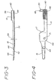
- FIGs. 3 and 4 show the movable portion 14 of the blade holder separated from the fixed portion thereof for clarity.
- this view is the opposite side of portion 14 from that of Figs. 1 and 2, and 14 includes a plurality of spaced frictional ridges providing a frictional gripping surface 46.
- This surface serves to provide the user with a frictional surface for the thumb or finger for the opening movement necessary to open the device to allow the blade to drop from the open blade holder 10.
- Surface 56 on the front end portion of the blade half 14 preferably includes an opening 44 which cooperates with abutment 23 on the fixed portion of the device for maintaining the blade fixed between the cooperating surfaces of the fixed and rotating halves of holder 10 of the invention.
- the front portion 16 from the pivot axis 29 as shown in Fig. 3 is bowed slightly along the surface 56 to provide a more firm cooperating wedging action between surface 56 and the cooperating surface on the other half 12 of the blade holder 10.
- Both the fixed and rotating halves of the blade holder include beveled edges 36 and 38, which provide a further ease of holding and/or gripping the holder during use.
- the movable half 14 of the holder includes a bore 31 for receiving the rotating pivot pin 24.
- FIGs. 5 and 6 the fixed half 12 of the holder 10 is shown separately from the movable half thereof.
- bearing surfaces 52 and 53 are shown for cooperating with opposed surfaces on the movable half 14 of the blade 10.
- Surface 53 serves as a "stop" for movement to the closed position of the part 14 in cooperation with the movement of the abutment 48 into depression 30 to cause locking together of the two halves once the blade is in place between the two halves.
- Fixed blade holder half 12 also includes a bore 27 for receiving the pivot pin 24 as discussed above.
- the fixed blade holder half 12 includes vertical ridges 34 and 35, as viewed in Figs. 5 and 6, on opposite sides thereof in order to provide the user with a frictional surface for ease of holding the holder 10 during use.
- the user grips the proximal end of the fixed portion 12 of the invention.
- a large portion of the elongated device is removed from any movable part so as to provide a gripping surface for opening and closing the device.
- the user places a thumb or finger against the surface 46 to provide a force for opening the movable portion 14 to expose the boss 20 and opposed locking wedges 22 and 23 for receiving the opening of a tang of a blade selected for insertion into the holder 10.
- the force for opening overcomes the cooperating locking surfaces of parts 48 and 30 of the two halves of the holder.
- the user may place the blade appropriately with the opening of the blade over the boss 20. Then, the user simply moves the movable holder portion 14 so as to cause the abutment 48 to move in position in the depression 30 for locking the two parts together. With this movement, the blade is fixed in place with no "wobbling" in the holder. Then the user may use the holder with the blade in an appropriate desired way.
- the contaminated blade may be removed readily by the user. This is done simply by, again, holding the prioximal end of the fixed portion 12 of the device 10 of the invention and placing the thumb or finger against the frictional surface 46 for movement of the rotating portion 14 around pivot axis 29. This force overcomes the locking engagement of cooperating parts 30 and 48 and allows the two parts to open to a position as shown in Fig. 1. Thereafter, the user may, if the boss 20 is positioned upwardly, simply turn the holder so that the boss is positioned downwardly and the blade will fall out into a container provided for that purpose.
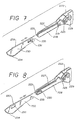
- Figs. 7 and 8 are exploded isometric views of a surgical blade holders of the invention showing a blade 230 and a cooperating blade receiving area 228 on a fixed handle portion 222.
- the rotatable handle portion is not shown so that blade receiving area 228 can be seen more clearly.
- the blade 230 is loaded into the holder with the fixed and rotatable handle portions in the closed position. Therefore, blade 230 can be slid, for example, from a blade dispensing device, between the distal ends of the fixed and rotatable handle portions and locked in place using one of the arrangements described below or equivalents thereof.
- blade 230 includes a cutting edge 234 surrounding the distal end of the blade, a tab 231 projecting from the surface of the blade, and a rib 233 extending between the distal end of the blade towards proximal end 235 of the blade.
- Distal end 223 of fixed handle portion 222 also includes a pivot axis 229 about which a rotatable handle portion (not shown) rotates to permit the holder to move between an opened position and a closed position. As shown in Fig.
- blade receiving area 228 at distal end 223 includes (i) a slanted depression 219 in the proximal end of blade receiving area 228 for receiving tab 231 on blade 230 and (ii) a groove 227 that extends from distal end 223 towards the proximal end of blade receiving area 228 for receiving rib 233 on blade 230.
- Fixed handle portion 222 also includes a rear mating surface 225 that engages with proximal end 235 of blade 230, when blade 230 is fully mounted in blade receiving area 228.
- rib 233 slides in groove 227 until tab 231 is received by depression 219 and proximal end 235 of blade 230 mates with rear mating surface 225.
- tab 231 mates with depression 219 the blade is locked in the holder and thereby secured in three-dimensions.
- tab 231 on tang of blade 230 permits a user to easily pick up blade 230 from a flat surface, if necessary, without having to touch cutting edge 234.
- holder and blade arrangement shown in Fig. 8 is substantially similar to the arrangement shown in Fig. 7. However, tab 231 and depression 219 in Fig. 7 have been replaced with an opening 232 in blade 230 and a slanted abutment 220 at distal end 223, of fixed handle portion 222.
- Fig. 8 shows blade receiving area 228 on fixed handle portion 222 including (i) slanted abutment 220 which receives opening 232 in blade 230 and (ii) groove 227 extending between distal end 223 to the proximal end of blade receiving area, 228 which receives rib 233.
- slanted abutment 220 is received by opening 232 in blade 230 to lock blade 230 in the holder and secure it in three-dimensions when it has been fully mounted in the holder.
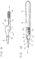
- FIGs. 9 and 10 An alternative locking mechanism for a surgical blade holder of the present invention is shown in Figs. 9 and 10.
- Fig. 9 shows a side elevational view of rotatable handle portion 14 of the surgical blade holder having a locking channel 406 that forms a part of the alternative Locking mechanism. Note that elements of handle portion 14 similar to elements in the handle portion shown in Fig. 4 are identified using the same reference numbers. Rotatable handle portion 14 in Fig. 9, however, does not include locking extension 26 shown in Fig. 4.
- the alternative locking mechanism also includes locking protrusion 408 on fixed handle portion 12, as shown in Fig. 10.
- Locking protrusion 408 is positioned on fixed handle portion 12 so to mate with locking channel 406 on rotatable handle portion 14, when the device is in a closed position.
- the elements of fixed handle portion 12 in Fig. 10 in common with elements in the fixed handle portion shown in Fig. 4 are identified using the same reference numerals.
Landscapes
- Health & Medical Sciences (AREA)
- Life Sciences & Earth Sciences (AREA)
- Engineering & Computer Science (AREA)
- Surgery (AREA)
- Molecular Biology (AREA)
- Biomedical Technology (AREA)
- Heart & Thoracic Surgery (AREA)
- Medical Informatics (AREA)
- Nuclear Medicine, Radiotherapy & Molecular Imaging (AREA)
- Animal Behavior & Ethology (AREA)
- General Health & Medical Sciences (AREA)
- Public Health (AREA)
- Veterinary Medicine (AREA)
- Forests & Forestry (AREA)
- Mechanical Engineering (AREA)
- Surgical Instruments (AREA)
Applications Claiming Priority (3)
| Application Number | Priority Date | Filing Date | Title |
|---|---|---|---|
| US944857 | 1992-09-14 | ||
| US07/944,857 US5272812A (en) | 1990-11-13 | 1992-09-14 | Surgical blade holder and blade combination |
| EP93114371A EP0588220B1 (de) | 1992-09-14 | 1993-09-08 | Chirurgische Klingenhalterung und Klingenkombination |
Related Parent Applications (1)
| Application Number | Title | Priority Date | Filing Date |
|---|---|---|---|
| EP93114371.3 Division | 1993-09-08 |
Publications (1)
| Publication Number | Publication Date |
|---|---|
| EP0950375A2 true EP0950375A2 (de) | 1999-10-20 |
Family
ID=25482182
Family Applications (2)
| Application Number | Title | Priority Date | Filing Date |
|---|---|---|---|
| EP99113209A Withdrawn EP0950375A2 (de) | 1992-09-14 | 1993-09-08 | Chirurgische Klingenhalterung und Klingenkombination |
| EP93114371A Expired - Lifetime EP0588220B1 (de) | 1992-09-14 | 1993-09-08 | Chirurgische Klingenhalterung und Klingenkombination |
Family Applications After (1)
| Application Number | Title | Priority Date | Filing Date |
|---|---|---|---|
| EP93114371A Expired - Lifetime EP0588220B1 (de) | 1992-09-14 | 1993-09-08 | Chirurgische Klingenhalterung und Klingenkombination |
Country Status (7)
| Country | Link |
|---|---|
| US (2) | US5272812A (de) |
| EP (2) | EP0950375A2 (de) |
| JP (1) | JP2559201B2 (de) |
| AT (1) | ATE189109T1 (de) |
| AU (1) | AU662069B2 (de) |
| CA (1) | CA2106023C (de) |
| DE (1) | DE69327694D1 (de) |
Cited By (1)
| Publication number | Priority date | Publication date | Assignee | Title |
|---|---|---|---|---|
| CN103190943A (zh) * | 2013-04-29 | 2013-07-10 | 昆山千寻金属制品有限公司 | 一种新型医疗用手术刀 |
Families Citing this family (36)
| Publication number | Priority date | Publication date | Assignee | Title |
|---|---|---|---|---|
| US5827309A (en) * | 1994-10-25 | 1998-10-27 | Becton, Dickinson And Company | Guarded surgical scalpel with scalpel blade remover |
| US6530903B2 (en) | 2000-02-24 | 2003-03-11 | Xiping Wang | Safety syringe |
| USD490153S1 (en) | 2002-12-27 | 2004-05-18 | Becton Dickinson And Company | Blade carrier |
| USD483123S1 (en) | 2002-12-27 | 2003-12-02 | Becton Dickinson And Company | Blade carrier |
| USD482788S1 (en) | 2002-12-27 | 2003-11-25 | Becton Dickinson And Company | Blade carrier |
| SI1437201T1 (sl) * | 2003-01-13 | 2005-12-31 | Vermop Salmon Gmbh | Drzalo britvice |
| USD481129S1 (en) | 2003-01-29 | 2003-10-21 | Becton Dickinson And Company | Blade holder |
| US20040186493A1 (en) * | 2003-03-17 | 2004-09-23 | Mcwhorter Paul Jackson | Microkeratome cutting head assembly with single bevel cutting blade |
| US20040181950A1 (en) | 2003-03-17 | 2004-09-23 | Rodgers Murray Steven | Alignment of microkeratome blade to blade handle |
| US8291601B2 (en) | 2005-04-01 | 2012-10-23 | Pankaj Kehr | Reusable metal blade handle |
| US8978254B1 (en) * | 2006-08-28 | 2015-03-17 | James Dale White | Exchange blade knife |
| US7900363B1 (en) | 2006-08-28 | 2011-03-08 | James Dale White | Exchange blade knife |
| US10492817B2 (en) | 2009-03-09 | 2019-12-03 | A.M. Surgical, Inc. | Endoscopic surgical blade and use thereof |
| WO2011108100A1 (ja) * | 2010-03-04 | 2011-09-09 | フェザー安全剃刀株式会社 | 刃物 |
| CN104470447B (zh) | 2012-07-12 | 2018-04-27 | 新特斯有限责任公司 | 锯、锯刀片和连接机构 |
| US10493641B2 (en) | 2012-10-26 | 2019-12-03 | Outdoor Edge Cutlery Corporation | Folding knife with replaceable blade |
| CN103786170B (zh) | 2012-10-26 | 2016-02-10 | 奥多艾格刀具公司 | 具有可替换刀片的刀具 |
| US9132561B2 (en) | 2013-03-13 | 2015-09-15 | Margret E. Leventhal | Laboratory cutting device |
| USD869254S1 (en) | 2013-10-25 | 2019-12-10 | Outdoor Edge Cutlery Corporation | Blade |
| USD747637S1 (en) | 2014-10-31 | 2016-01-19 | Outdoor Edge Cutlery Corporation | Double blade knife |
| CN105726128B (zh) * | 2016-04-13 | 2018-09-21 | 李建涛 | 一种手术台上手术刀片悬挂架 |
| CN108236486A (zh) * | 2016-12-23 | 2018-07-03 | 昆山源科弘森金属科技有限公司 | 微创手术刀的制造方法 |
| CN207371905U (zh) * | 2017-07-13 | 2018-05-18 | 杭州巨星科技股份有限公司 | 一种清理工具 |
| US10716592B2 (en) | 2017-09-05 | 2020-07-21 | Aspen Surgical Products Inc. | Scalpel blade loader |
| USD909170S1 (en) | 2019-01-08 | 2021-02-02 | Outdoor Edge Cutlery Corporation | Knife |
| USD918683S1 (en) | 2019-10-31 | 2021-05-11 | Outdoor Edge Cutlery Corporation | Replaceable blade |
| USD926551S1 (en) | 2020-01-21 | 2021-08-03 | Outdoor Edge Cutlery Corporation | Knife |
| USD989580S1 (en) | 2021-04-16 | 2023-06-20 | Outdoor Edge Cutlery, Llc | Replaceable blade |
| USD1009587S1 (en) | 2022-03-11 | 2024-01-02 | Outdoor Edge Cutlery, Llc | Caping blade |
| USD1107856S1 (en) | 2023-07-14 | 2025-12-30 | Outdoor Edge Cutlery, Llc | Knife handle |
| USD1047657S1 (en) | 2023-07-14 | 2024-10-22 | Outdoor Edge Cutlery, Llc | Knife handle |
| USD1046591S1 (en) | 2023-07-14 | 2024-10-15 | Outdoor Edge Cutlery, Llc | Blade holder |
| USD1046589S1 (en) | 2023-07-14 | 2024-10-15 | Outdoor Edge Cutlery, Llc | Knife handle |
| USD1047656S1 (en) | 2023-07-14 | 2024-10-22 | Outdoor Edge Cutlery, Llc | Knife handle |
| USD1047654S1 (en) | 2023-07-14 | 2024-10-22 | Outdoor Edge Cutlery, Llc | Blade holder |
| USD1086841S1 (en) | 2024-07-22 | 2025-08-05 | Outdoor Edge Cutlery, Llc | Knife blade |
Family Cites Families (16)
| Publication number | Priority date | Publication date | Assignee | Title |
|---|---|---|---|---|
| US1261815A (en) * | 1916-11-09 | 1918-04-09 | George William Housdorfer | Surgical knife. |
| US1554083A (en) * | 1925-01-17 | 1925-09-15 | Goldman Gustav | Knife with separable blade |
| US1823001A (en) * | 1931-02-07 | 1931-09-15 | Rassier Frank | Razor blade holder |
| US1914153A (en) * | 1931-09-08 | 1933-06-13 | John J Ogden | Surgical knife |
| US2039443A (en) * | 1934-01-17 | 1936-05-05 | John J Ogden | Surgical knife |
| US2064176A (en) * | 1934-01-25 | 1936-12-15 | Bardparker Company Inc | Detachable blade knife |
| US2191276A (en) * | 1936-12-21 | 1940-02-20 | Joseph A Gardner | Knife |
| GB713101A (en) * | 1951-11-16 | 1954-08-04 | Alorix Ltd | Improvements in razor blade holders |
| US2708313A (en) * | 1952-05-12 | 1955-05-17 | William E Steele | Detachable blade scalpels |
| US3262205A (en) * | 1964-01-21 | 1966-07-26 | Ruth B Arden | Scalpel |
| US3802077A (en) * | 1972-08-02 | 1974-04-09 | M Averitt | Tool holder |
| JPS56144509U (de) * | 1980-03-31 | 1981-10-31 | ||
| US4617738A (en) * | 1984-04-25 | 1986-10-21 | Becton, Dickinson And Company | Surgical blade handle |
| JPH0323211Y2 (de) * | 1985-08-06 | 1991-05-21 | ||
| US5146685A (en) * | 1990-11-13 | 1992-09-15 | Becton, Dickinson And Company | Multi-dimensional surgical blade holder and blade combination |
| US5060387A (en) * | 1990-11-13 | 1991-10-29 | Becton, Dickinson And Company | Blade handle |
-
1992
- 1992-09-14 US US07/944,857 patent/US5272812A/en not_active Expired - Fee Related
-
1993
- 1993-08-30 AU AU44984/93A patent/AU662069B2/en not_active Ceased
- 1993-09-08 EP EP99113209A patent/EP0950375A2/de not_active Withdrawn
- 1993-09-08 AT AT93114371T patent/ATE189109T1/de not_active IP Right Cessation
- 1993-09-08 DE DE69327694T patent/DE69327694D1/de not_active Expired - Lifetime
- 1993-09-08 EP EP93114371A patent/EP0588220B1/de not_active Expired - Lifetime
- 1993-09-13 CA CA002106023A patent/CA2106023C/en not_active Expired - Fee Related
- 1993-09-14 JP JP5229210A patent/JP2559201B2/ja not_active Expired - Lifetime
- 1993-09-20 US US08/124,122 patent/US5430942A/en not_active Expired - Lifetime
Cited By (1)
| Publication number | Priority date | Publication date | Assignee | Title |
|---|---|---|---|---|
| CN103190943A (zh) * | 2013-04-29 | 2013-07-10 | 昆山千寻金属制品有限公司 | 一种新型医疗用手术刀 |
Also Published As
| Publication number | Publication date |
|---|---|
| EP0588220A3 (de) | 1994-10-26 |
| EP0588220B1 (de) | 2000-01-26 |
| JP2559201B2 (ja) | 1996-12-04 |
| CA2106023C (en) | 1998-11-24 |
| JPH06169928A (ja) | 1994-06-21 |
| AU662069B2 (en) | 1995-08-17 |
| EP0588220A2 (de) | 1994-03-23 |
| AU4498493A (en) | 1994-03-24 |
| US5272812A (en) | 1993-12-28 |
| US5430942A (en) | 1995-07-11 |
| ATE189109T1 (de) | 2000-02-15 |
| CA2106023A1 (en) | 1994-03-15 |
| DE69327694D1 (de) | 2000-03-02 |
Similar Documents
| Publication | Publication Date | Title |
|---|---|---|
| EP0588220B1 (de) | Chirurgische Klingenhalterung und Klingenkombination | |
| US4903390A (en) | Scalpel blade remover and blade storage apparatus | |
| US5868771A (en) | Scalpel blade cover | |
| US5741289A (en) | Cleanable guarded surgical scalpel with scalpel blade remover | |
| US5088173A (en) | One-time-use precision-blade-bending scalpel blade remover-receptacle | |
| EP1289435B1 (de) | Chirurgische vorrichtung mit einziehbarer klinge in einem geschlossenen kanal | |
| US7243826B2 (en) | Pill box and splitter with blade guard | |
| JP2814429B2 (ja) | ブレード取り外し具を備えた保護装置付きの外科手術用メス | |
| EP0343803A2 (de) | Sicherheitseinrichtung zum Einbringen eines Katheters | |
| US5341822A (en) | Bandage cutter and remover | |
| US20260027737A1 (en) | Knife having sheath and bottle opener | |
| TWI316400B (en) | Scalpel blade remover and method of using the same | |
| RU2144334C1 (ru) | Извлекатель лезвия скальпеля | |
| US5699908A (en) | Scalpel blade removal and storage apparatus | |
| HUP9904133A2 (hu) | Egyszer használatos szike | |
| US5522828A (en) | Surgical knife with blade shield | |
| US20080300612A1 (en) | Cutting blade storage apparatus | |
| AU706994B2 (en) | Medical sharps and blades removal and containment structure | |
| EP0485764B1 (de) | Messergriff | |
| US5255422A (en) | Scalpel blade on-off tool | |
| US4640274A (en) | Surgical needle extractor having a disposable chuck, a chuck and a handle | |
| US5146685A (en) | Multi-dimensional surgical blade holder and blade combination | |
| JP2005040573A (ja) | 使い捨て手術用メス | |
| IL106542A (en) | Locked safety catheter |
Legal Events
| Date | Code | Title | Description |
|---|---|---|---|
| PUAI | Public reference made under article 153(3) epc to a published international application that has entered the european phase |
Free format text: ORIGINAL CODE: 0009012 |
|
| AC | Divisional application: reference to earlier application |
Ref document number: 588220 Country of ref document: EP |
|
| AK | Designated contracting states |
Kind code of ref document: A2 Designated state(s): AT BE CH DE DK ES FR GB GR IT LI LU NL SE |
|
| STAA | Information on the status of an ep patent application or granted ep patent |
Free format text: STATUS: THE APPLICATION HAS BEEN WITHDRAWN |
|
| 18W | Application withdrawn |
Effective date: 20030618 |