EP0950293B1 - Überwachungssystem unter verwendung des optischen rückhörsignals als testsignal - Google Patents
Überwachungssystem unter verwendung des optischen rückhörsignals als testsignal Download PDFInfo
- Publication number
- EP0950293B1 EP0950293B1 EP97911628A EP97911628A EP0950293B1 EP 0950293 B1 EP0950293 B1 EP 0950293B1 EP 97911628 A EP97911628 A EP 97911628A EP 97911628 A EP97911628 A EP 97911628A EP 0950293 B1 EP0950293 B1 EP 0950293B1
- Authority
- EP
- European Patent Office
- Prior art keywords
- optical
- lme
- test signal
- signal
- tone
- Prior art date
- Legal status (The legal status is an assumption and is not a legal conclusion. Google has not performed a legal analysis and makes no representation as to the accuracy of the status listed.)
- Expired - Lifetime
Links
- 230000003287 optical effect Effects 0.000 title claims abstract description 60
- 238000012544 monitoring process Methods 0.000 title claims abstract description 40
- 238000012360 testing method Methods 0.000 title claims description 37
- 230000005540 biological transmission Effects 0.000 claims abstract description 31
- 230000003595 spectral effect Effects 0.000 claims description 9
- 239000000835 fiber Substances 0.000 abstract description 45
- 230000003111 delayed effect Effects 0.000 abstract description 8
- 238000000034 method Methods 0.000 description 9
- 239000013307 optical fiber Substances 0.000 description 7
- 230000001934 delay Effects 0.000 description 3
- 230000015556 catabolic process Effects 0.000 description 2
- 238000004891 communication Methods 0.000 description 2
- 230000007423 decrease Effects 0.000 description 2
- 238000006731 degradation reaction Methods 0.000 description 2
- 238000010586 diagram Methods 0.000 description 2
- 238000003780 insertion Methods 0.000 description 2
- 230000037431 insertion Effects 0.000 description 2
- 238000010521 absorption reaction Methods 0.000 description 1
- 238000010420 art technique Methods 0.000 description 1
- 230000002238 attenuated effect Effects 0.000 description 1
- 230000002457 bidirectional effect Effects 0.000 description 1
- 230000000903 blocking effect Effects 0.000 description 1
- 230000006735 deficit Effects 0.000 description 1
- 230000000737 periodic effect Effects 0.000 description 1
- 238000012545 processing Methods 0.000 description 1
- 238000001228 spectrum Methods 0.000 description 1
Images


Classifications
-
- H—ELECTRICITY
- H04—ELECTRIC COMMUNICATION TECHNIQUE
- H04B—TRANSMISSION
- H04B10/00—Transmission systems employing electromagnetic waves other than radio-waves, e.g. infrared, visible or ultraviolet light, or employing corpuscular radiation, e.g. quantum communication
- H04B10/07—Arrangements for monitoring or testing transmission systems; Arrangements for fault measurement of transmission systems
- H04B10/075—Arrangements for monitoring or testing transmission systems; Arrangements for fault measurement of transmission systems using an in-service signal
- H04B10/077—Arrangements for monitoring or testing transmission systems; Arrangements for fault measurement of transmission systems using an in-service signal using a supervisory or additional signal
- H04B10/0771—Fault location on the transmission path
-
- H—ELECTRICITY
- H04—ELECTRIC COMMUNICATION TECHNIQUE
- H04B—TRANSMISSION
- H04B10/00—Transmission systems employing electromagnetic waves other than radio-waves, e.g. infrared, visible or ultraviolet light, or employing corpuscular radiation, e.g. quantum communication
- H04B10/07—Arrangements for monitoring or testing transmission systems; Arrangements for fault measurement of transmission systems
- H04B10/075—Arrangements for monitoring or testing transmission systems; Arrangements for fault measurement of transmission systems using an in-service signal
- H04B10/077—Arrangements for monitoring or testing transmission systems; Arrangements for fault measurement of transmission systems using an in-service signal using a supervisory or additional signal
- H04B10/0777—Monitoring line amplifier or line repeater equipment
-
- H—ELECTRICITY
- H04—ELECTRIC COMMUNICATION TECHNIQUE
- H04B—TRANSMISSION
- H04B2210/00—Indexing scheme relating to optical transmission systems
- H04B2210/07—Monitoring an optical transmission system using a supervisory signal
- H04B2210/075—Monitoring an optical transmission system using a supervisory signal using a pilot tone
-
- H—ELECTRICITY
- H04—ELECTRIC COMMUNICATION TECHNIQUE
- H04B—TRANSMISSION
- H04B2210/00—Indexing scheme relating to optical transmission systems
- H04B2210/07—Monitoring an optical transmission system using a supervisory signal
- H04B2210/078—Monitoring an optical transmission system using a supervisory signal using a separate wavelength
Definitions
- the present invention relates to communication systems and more particularly to a system for monitoring a fiber optic transmission system using an optical side tone as a test signal.
- monitoring can be used to detect faults or breaks in the fiber optic cable, faulty repeaters or amplifiers or other problems with the system.
- Prior art monitoring techniques include the use a testing system which generates a test signal and modulating the test signal onto a single channel (or wavelength) with the transmitted data signal.
- the data signal may be amplitude modulated by the test signal.
- a loop-back coupler within an optical amplifier or repeater located downstream is used to return a portion of the transmitted signal (data signal plus test signal modulation) to the testing system.
- the testing system then separates the test signal from the data signal and processes the test signal to examine the health of the transmission system.
- U.S. Patents 4,586,186 and 4,633,464 to Cleo Anderson et al. and assigned to AT&T disclose a similar technique to modulate test response information from a repeater onto the main data signal to monitor the health of the system.
- Fig. 1A illustrates the test signal 12 and the data signal ("1"s and "0"s) prior to modulation.
- data bit 10 is above the threshold level 14 and therefore is a "1.”
- amplitude modulating the data signal with the test signal can cause the amplitude of data bit 10 to significantly decrease. Due to this interference from the test signal modulation combined with the ordinary attenuation of the data signal, the amplitude of data bit 10 may decline below the threshold level for a "1," resulting in an erroneous bit (Fig. 1B). Consequently, prior art monitoring systems require additional optical amplifiers or repeaters to compensate for losses resulting from test signal modulation.
- the prior art monitoring systems described above are incapable of simultaneously monitoring more than a single channel.
- two or more wavelengths (or channels) may be used to carry information over the same optical fiber. This is known as wavelength-division multiplexing (WDM).
- WDM wavelength-division multiplexing
- the prior art monitoring technique described above uses a test signal having the same wavelength as the data signal, and therefore, can test only a single channel at a time. A separate testing system for each wavelength or channel would be required to simultaneously monitor multiple channels using the prior art technique. As a result, such a system would have a prohibitively high cost.
- GB-A-2 294 373 discloses a supervisory loopback circuit and transceiver circuit for an optical repeater system having a plurality of optical repeaters.
- a need has arisen for a monitoring system that does not attenuate data signals and which is capable of simultaneously monitoring multiple channels (wavelengths) on an optical fiber.
- the monitoring system of the present invention improves upon existing monitoring systems by providing a monitoring system that impairs data signals significantly less than prior art systems.
- the monitoring system of the present invention also provides a monitoring technique that can be used to simultaneously monitor a plurality of channels.
- the monitoring system of the present invention includes a line monitoring equipment (LME) for monitoring the health of a telecommunications transmission system, such as a fiber optic transmission system.
- LME comprises a pseudo-random sequence (PRS) tone generator generating a PRS tone and a laser transmitter connected to the tone generator for generating an LME side tone based on the PRS tone.
- PRS pseudo-random sequence
- the LME further includes an optical filter for passing only the frequency of the LME side tone and a delay system connected to the tone generator.
- the LME also includes a comparator/correlator for correlating an output of the delay system with an output of the optical filter.
- the monitoring system of the present invention also includes an optical coupler combining the test signal with one or more data signals into a combined signal.
- Each data signal has its own data channel.
- the LME side tone has a frequency outside the frequency bandwidth of each data channel.
- the monitoring system also includes a repeater connected to the optical coupler and having an optical loopback coupler.
- the optical loopback coupler returns a portion of the combined signal to the optical filter of the LME.
- the filter passes the wavelength of the LME side tone to the comparator/correlator.
- a delay system is connected to the PRS tone generator and the comparator/correlator for delaying the PRS tone based on a location of the repeater.
- the PRS tone is delayed a separate time, t N , proportional to the length, d N , of the delay path for each repeater.
- a comparator/correlator outputs a result of the correlation operation that can be used by a computer or other system for monitoring the fiber optic transmission system, including detecting and diagnosing the location of faults or other problems.
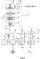
- FIG. 2 illustrates a monitoring system 10 according to the present invention.
- Monitoring system 10 includes a line monitoring equipment (LME) 12 for monitoring the health of a telecommunications transmission system, such as a fiber optic transmission system.
- LME 12 includes pseudo-random sequence (PRS) tone generator 14 connected to laser transmitter 16 for generating and outputting a pseudo-random sequence of tones.
- Laser transmitter 16 generates an LME side tone 18 based on the tones generated by PRS tone generator 14.
- LME side tone 18 is used as a test tone by LME 12 to monitor the health of a fiber optic transmission system.
- LME 12 also includes a delay system 20 connected to PRS tone generator 14 for delaying the tones received from PRS tone generator 14.
- LME 12 further includes an optical filter 26 for selectively transmitting one or more wavelengths or channels, while blocking the transmission of other wavelengths.
- Comparator/correlator 22 is connected to delay system 20 and optical filter 26. Comparator/correlator 22 correlates the outputs of optical filter 26 and delay system 20 using well known digital signal processing techniques. Comparator/correlator 22 outputs a result 24 of the correlation operation which is used by a computer or other systems (not shown) to diagnose faults or problems in the optical transmission system.
- LME 12 is connected to a portion of an optical transmission system.
- the optical transmission system includes a laser transmitter 30 and an optical fiber pair, including fibers 28 and 29, for carrying optical signals.
- Fibers 28 and 29 can be the long distance optical fiber lines for deployment, for example, under the ocean.
- Optical fibers 28 and 29 are unidirectional fibers and carry signals in opposite directions. Fibers 28 and 29 together provide a bidrectional path for transmitting signals. While the monitoring system according to a disclosed embodiment of the present invention monitors a transmission system that includes two unidirectional fibers 28 and 29, the present invention may be used to monitor transmission systems employing a single bidirectional fiber.
- Laser transmitter 30 transmits optical data on a plurality of channels (or wavelengths) over fiber 29.
- Laser transmitter 30 can comprise a plurality of laser transmitters each transmitting an optical data signal over fiber 29 using a different channel or wavelength.
- a plurality of data signals each at a different wavelength are sent over fiber 29 using wavelength-division multiplexing (WDM).
- WDM wavelength-division multiplexing
- WDM data signals may be carried over fiber 28, but traveling in a direction opposite of those signals on fiber 29.
- a coupler 34 combines the WDM data 32 from transmitter 30 and LME side tone 18 from transmitter 16 and outputs this combined signal for transmission onto fiber 29.
- a first optical repeater 36 receives the combined signal from coupler 34.
- Repeater 36 includes amplifiers 38 and 40 for amplifying optical signals transmitted over fibers 28 and 29, respectively.
- Repeater 36 also includes a loop-back coupler 42 which returns a portion of the signal being transmitted on fiber 29 to fiber 28 for transmission to LME 12.
- a second optical repeater 44 includes amplifiers 46 and 48 and loop-back coupler 50. Additional optical repeaters, including their associated loop-back couplers, are connected to fibers 28 and 29 for periodically amplifying and returning signals thereon.
- Signal 52 is connected to the end of fiber 28 and carries all signals present on fiber 28, including the combined WDM data 32 and LME side tones 18 returned by loop-back couplers 42 and 50 returned over fiber 28.
- Signal 52 is input to optical filter 26.
- Optical filter 26 is wavelength selective and passes only the wavelength of LME side tone 18.
- Comparator/correlator 22 then correlates the returned LME side tone with the delayed PRS tones. Comparator/correlator 22 may correlate electrical signals or optical signals. Where comparator/correlator 22 correlates electrical signals, LME 12 further includes an optical decoder connected between optical filter 26 and the comparator/correlator 22 for converting the optical signals output by filter 26 into electrical signals.
- the monitoring system of Fig. 2 may be used to simultaneously monitor a plurality of channels on both fibers 28 and 29 without attenuating the WDM data 32.
- Fig. 3A illustrates an example of the spectrum of channels transmitted over the optical fiber 29 in Fig. 2.
- the different data channels transmitted on fiber 29 by laser 30 using WDM include data channels 60-64, having different wavelengths ⁇ 0 - ⁇ 4 , respectively, and bandwidths 70-74, respectively. Additional data channels or fewer data channels having their respective wavelengths may also be carried on the optical fiber 29. Alternatively, some of the data channels 60-64 may be carried in the opposite direction over fiber 28, instead of over fiber 29.
- Coupler 34 combines the LME side tone 18 having a wavelength ⁇ T with the data channels onto fiber 29.
- ⁇ T is different from the wavelengths of all other channels carried on the fiber.
- the LME side tone 18 has a frequency outside of the frequency bandwidth of all other channels transmitted over fibers 28 and 29. As a result, the LME side tone 18 does not attenuate or interfere with the data channels.
- the LME side tone 18 may be inserted at the edge of the spectral bandwidth of the system as shown in Fig. 3A, or inserted between data channels as shown in Fig. 3B.
- ⁇ 2 may be 1555 nm
- ⁇ 3 may be 1556 nm
- ⁇ T may be inserted between these two data channels at a wavelength of 1555.5 nm.
- the power of LME side tone 18 may be adjusted by laser 16 and should be set significantly below the power level of the data signals communicated over fibers 28 and 29 to minimize the impairment of the data signals.
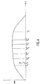
- Fig. 4 illustrates the spectral bandwidth of the system and is defined by the lower limit ⁇ a and the upper limit ⁇ b .
- Fig. 4 may represent the gain characteristics of one or more of the repeaters or amplifiers in the system which limit and define the spectral characteristics of the system.
- the upper and lower limits of the spectral bandwidth of the system specify the range of wavelength values where LME side tone 18 may be inserted.
- LME side tone 18 (wavelength of ⁇ T ) may be inserted between the lower limit ⁇ a and the first data channel (wavelength of X 0 ) .
- the LME side tone 18 may be inserted anywhere between limits ⁇ a and ⁇ b , so long as LME side tone 18 has a frequency outside the frequency bandwidth of the data channels on the system.
- LME 12 may measure the spectral bandwidth of the system by moving LME side tone 18 to different positions (or wavelengths) and analyzing the resulting signals returned to LME 12 from repeaters 36 and 44 at each position. For example, when the LME side tone 18 is inserted at a wavelength which is outside of the spectral bandwidth of the system, limiting components in the system (such as repeaters or amplifiers) will attenuate or reject some or all of the LME side tone 18. In such case, the attenuated or non-existent LME side tone returned to LME 12 can be detected by the computer or system connected to the output of comparator/correlator 22.
- LME 12 processes LME side tone 18 to monitor the optical transmission system.
- LME 12 generates LME side tone 18 for use in monitoring the fiber optic transmission system.
- Coupler 34 combines the plurality of WDM data channels 32 transmitted by transmitter 30 with the LME side tone 18 for transmission over fiber 29.
- the combined signal is amplified by first repeater 36.
- Loop-back coupler 42 within repeater 36 returns a portion of the combined signal to LME 12 over fiber 28.
- Second repeater 44 similarly amplifies and returns a portion of the combined signal to LME 12 over fiber 28 and signal 52. Therefore, after transmitting LME side tone 18, LME 12 receives a delayed feedback (the returned LME side tone) from each respective repeater via signal 52.
- Optical filter 26 receives the combined signals from loop-back couplers 42 and 50 via signal 52.
- Optical filter 26 is wavelength selective and passes only the wavelength ( ⁇ T ) of the LME side tone 18 received from loop-back couplers 42 and 50 and rejects the wavelengths (i.e., ⁇ 0 - ⁇ 4 is shown in Figs. 3A and 3B) of the WDM data.
- the wavelength ( ⁇ T ) of the LME side tone 18 must be different from the wavelengths of other signals carried on fibers 28 and 29 so that filter 26 may pass only the wavelength ⁇ T ) of the returned LME side tone. Because the frequency of LME side tone 18 is outside the bandwidths of the data channels carried on the fiber, insertion of LME side tone 18 does not attenuate or interfere with the data channels.
- the LME side tones returned to LME 12 by each repeater via fiber 28 and signal 52 are delayed from the original LME side tone 18 a time period proportional to the lenght of the delay path for each repeater.
- the time delay t 1 is proportional to the length d 1 of the delay path through the first repeater.
- the distance d 1 may be calculated as the distance from the PRS tone generator 14, to transmitter 16, to coupler 34, to first repeater 36, through loop-back coupler 42, to the optical filter 26, and to comparator/correlator 22.
- time delays (t 3 , t 4 , t 5 , ...) for additional repeaters (not shown) in the system can also be calculated based on the known lengths of their delay paths.
- Comparator/correlator 22 correlates the PRS tones output by PRS tone generator 14 with each of the returned LME side tones.
- delay system 20 receives the PRS tones from PRS tone generator 14 and outputs a plurality of delayed PRS tones to comparator/correlator 22.
- Delay system 20 outputs each PRS tone after the time delays corresponding to each repeater: t 1 (corresponding to time delay for the first repeater 36), t 2 (corresponding to the time delay for the second repeater 44), t 3 , t 4 , etc., for each repeater in the system.
- delay system 20 delays the PRS tones based on the location of each repeater. This process is repeated for each PRS tone received by the delay system 20.
- Comparator/correlator 22 compares or correlates the delayed LME side tone returned from each repeater with correspondingly delayed PRS tones generated by PRS tone generator 14. Comparator/correlator 22 outputs a result 24 of the correlation operation that may be used by a computer or other system (not shown) for monitoring the fiber optic transmission system, including detecting and diagnosing the location of faults or other problems. In this manner, the monitoring system of the present invention allows multiple channels in an optical transmission system to be simultaneously monitored with minimal data attenuation or degradation.
- the PRS tone generator, delay system, and comparator/correlator can be either optical components or electrical components.
Landscapes
- Physics & Mathematics (AREA)
- Electromagnetism (AREA)
- Engineering & Computer Science (AREA)
- Computer Networks & Wireless Communication (AREA)
- Signal Processing (AREA)
- Optical Communication System (AREA)
- Monitoring And Testing Of Transmission In General (AREA)
- Testing Of Optical Devices Or Fibers (AREA)
Claims (11)
- Testsystem zum Überwachen eines WDM-Übertragungssystems, welches aufweist:einen Tongenerator (14), der dafür eingerichtet ist, einen Pseudozufallssequenz-Ton zu erzeugen,einen Lasersender (16), der mit dem Tongenerator gekoppelt ist und dafür eingerichtet ist, ein Testsignal (18) auf der Grundlage des Pseudozufallssequenz-Tons zu erzeugen,einen optischen Koppler (C), der dafür eingerichtet ist, das Testsignal (18) mit einem Datensignal (32) eines Datenkanals zu einem kombinierten Signal zu kombinieren, wobei das Testsignal (18) eine Frequenz außerhalb der Frequenzbandbreite des Datenkanals aufweist,einen Zwischenverstärker (36), der mit dem optischen Koppler (C) gekoppelt ist und eine optische Prüfschleife aufweist,ein optisches Filter (26), das mit dem Zwischenverstärker (36) gekoppelt ist,ein Verzögerungssystem (20), das mit dem Tongenerator (14) gekoppelt ist und dafür eingerichtet ist, das Testsignal auf der Grundlage eines Orts des Zwischenverstärkers zu verzögern, undeinen Vergleicher (22), der mit dem Verzögerungssystem (20) und dem optischen Filter (26) gekoppelt ist, wobei der Vergleicher (22) die Ausgabe des Verzögerungssystems (20) mit der Ausgabe des optischen Filters (26) korreliert.
- System nach Anspruch 1, wobei
das optische Filter (26) dafür eingerichtet ist, nur die Frequenz des Testsignals (18) durchzulassen, und der Vergleicher (22) einen Korrelator aufweist, und das System aufweist:eine Leitungsüberwachungseinrichtung (LME), welche aufweist:wobei die Prüfschleife einen Teil des kombinierten Signals zum optischen Filter der LME zurückführt.den Tongenerator,den Lasersender,das optische Filter,das Verzögerungssystem undden Korrelator, - System nach Anspruch 1 oder 2, wobei der Tongenerator, der Lasersender, das Verzögerungssystem und der Vergleicher einen Teil einer Leitungsüberwachungseinrichtung ausmachen.
- System nach Anspruch 1, 2 oder 3, wobei die Frequenz des Testsignals innerhalb der spektralen Bandbreite des WDM-Übertragungssystems liegt.
- System nach Anspruch 1, 2, 3 oder 4, wobei der Zwischenverstärker mehrere optische Zwischenverstärker aufweist, die sich an verschiedenen Orten entlang dem WDM-Übertragungssystem befinden, wobei jeder der optischen Zwischenverstärker eine optische Prüfschleife aufweist.
- System nach einem der Ansprüche 1 bis 5, wobei das optische Filter wellenlängenselektiv ist und nur die Wellenlänge des Testsignals durchlässt.
- System nach einem der Ansprüche 1 bis 6, wobei die optische Prüfschleife einen Teil eines kombinierten Signals, das das Testsignal und das Datensignal einschließt, zurückführt.
- System nach Anspruch 7, wobei das optische Filter das von der optischen Prüfschleife zurückkehrende optische Signal, einschließlich des Testsignals und des Datensignals, empfängt, wobei das optische Filter wellenlängenselektiv ist und nur die Wellenlänge des Testsignals zum Vergleicher durchlässt.
- System nach einem der Ansprüche 1 bis 8, wobei das Testsignal eine Frequenz aufweist, die sich in der Nähe des Rands der spektralen Bandbreite des WDM-Übertragungssystems befindet.
- System nach einem der Ansprüche 1 bis 9, wobei das Datensignal mehrere Datensignale einschließt, wobei jedes der Datensignale einen Datenkanal aufweist, wobei das Testsignal eine Frequenz aufweist, die sich außerhalb der Frequenzbandbreiten der Datenkanäle auf dem WDM-Übertragungssystem befindet.
- System nach einem der Ansprüche 1 bis 10, wobei das Testsignal eine Frequenz aufweist, die zwischen zweien der Datenkanäle auf dem WDM-Übertragungssystem liegt.
Applications Claiming Priority (3)
| Application Number | Priority Date | Filing Date | Title |
|---|---|---|---|
| US08/728,515 US5969833A (en) | 1996-10-09 | 1996-10-09 | Monitoring system using an optical side tone as a test signal |
| US728515 | 1996-10-09 | ||
| PCT/US1997/018074 WO1998016027A1 (en) | 1996-10-09 | 1997-10-08 | Monitoring system using an optical side tone as a test signal |
Publications (3)
| Publication Number | Publication Date |
|---|---|
| EP0950293A1 EP0950293A1 (de) | 1999-10-20 |
| EP0950293A4 EP0950293A4 (de) | 2005-06-15 |
| EP0950293B1 true EP0950293B1 (de) | 2006-08-23 |
Family
ID=24927168
Family Applications (1)
| Application Number | Title | Priority Date | Filing Date |
|---|---|---|---|
| EP97911628A Expired - Lifetime EP0950293B1 (de) | 1996-10-09 | 1997-10-08 | Überwachungssystem unter verwendung des optischen rückhörsignals als testsignal |
Country Status (8)
| Country | Link |
|---|---|
| US (1) | US5969833A (de) |
| EP (1) | EP0950293B1 (de) |
| JP (1) | JP4213218B2 (de) |
| AU (1) | AU719961B2 (de) |
| CA (1) | CA2267777C (de) |
| DE (1) | DE69736560T2 (de) |
| TW (1) | TW359922B (de) |
| WO (1) | WO1998016027A1 (de) |
Families Citing this family (40)
| Publication number | Priority date | Publication date | Assignee | Title |
|---|---|---|---|---|
| FR2769154B1 (fr) * | 1997-09-30 | 1999-12-03 | Thomson Csf | Dispositif de synchronisation precise |
| US6708004B1 (en) * | 1998-12-01 | 2004-03-16 | Tyco Telecommunications (Us) Inc. | Method and apparatus for reducing crosstalk between a monitoring channel and a data channel in a WDM optical communication system |
| US6414775B1 (en) * | 1998-12-28 | 2002-07-02 | Tycom (Us) Inc. | Method and apparatus for measuring gain shape in an optical repeater using FM modulation |
| US6134032A (en) * | 1999-04-02 | 2000-10-17 | Tyco Submarine Systems Ltd. | Method and apparatus for automatically identifying system faults in an optical communications system from repeater loop gain signatures |
| EP1122898A1 (de) * | 2000-01-31 | 2001-08-08 | KDD Corporation | Optisches Zwischenverstärkerüberwachungssystem und Verfahren dafür |
| US6778778B1 (en) * | 2001-01-11 | 2004-08-17 | Sprint Communications Company, L.P. | Arrangement and method for testing fiber optic telecommunications circuits over dense wavelength division multiplexing (DWDM) |
| US7394980B1 (en) * | 2001-01-11 | 2008-07-01 | Sprint Communications Company L.P. | Systems and methods for testing a circuit in a communication network |
| DE10112813A1 (de) * | 2001-03-16 | 2002-10-02 | Siemens Ag | Verfahren zur Datenübertragung mit einem optischen Wellenlängen-Multiplexsystem |
| US20020154351A1 (en) * | 2001-04-24 | 2002-10-24 | Feinberg Lee Daniel | Optical network architecture with reduced equipment |
| US20040105136A1 (en) * | 2001-05-08 | 2004-06-03 | Corvis Corporation | Interconnections and protection between optical communications networks |
| US6556319B2 (en) * | 2001-05-08 | 2003-04-29 | Dorsal Networks, Inc. | Split redundant trunk architecture using passive splitters and path switching |
| US6563979B2 (en) | 2001-06-22 | 2003-05-13 | Dorsal Networks, Inc. | Automatically switched redundant switch configurations |
| CA2449563C (en) * | 2001-06-22 | 2011-12-06 | John C. Carrick | System and method for measuring power of optical signals carried over a fiber optic link |
| US20030030861A1 (en) * | 2001-08-13 | 2003-02-13 | John Mellert | Methods for reliable communication of link monitoring information in optical communications networks |
| US20030030860A1 (en) * | 2001-08-13 | 2003-02-13 | John Mellert | Redundant line unit monitoring architecture |
| KR20020009542A (ko) * | 2001-12-06 | 2002-02-01 | 엔엠소프트(주) | 테스트신호를 이용한 광선로 및 원격지 통신국의 장비와환경을 감시하는 방법 및 이를 위한 장치 |
| US20040047295A1 (en) * | 2002-08-20 | 2004-03-11 | Morreale Jay P. | Method and apparatus for providing a common optical line monitoring and service channel over an WDM optical transmission system |
| US20040096214A1 (en) * | 2002-08-20 | 2004-05-20 | Red Sky Systems, Inc. | Method and apparatus for using optical idler tones for performance monitoring in a WDM optical transmission system |
| US20040096215A1 (en) * | 2002-08-20 | 2004-05-20 | Evangelides Stephen G. | Method and apparatus for performing system monitoring in a terminal independent interface located between a terrestrial optical terminal and an undersea optical transmission path |
| US20040126119A1 (en) * | 2002-08-20 | 2004-07-01 | Evangelides Stephen G. | Method and apparatus for providing a terminal independent interface between a terrestrial optical terminal and an undersea optical transmission path |
| KR20040022474A (ko) * | 2002-09-07 | 2004-03-16 | 엘지전자 주식회사 | 더블유디엠시스템에서의 디씨씨 성능 체크 및 데이터 전송장치 |
| KR100928142B1 (ko) * | 2002-09-11 | 2009-11-24 | 주식회사 케이티 | Otdr을 이용한 wdm-pon 광선로 감시장치 |
| JP3934529B2 (ja) * | 2002-10-30 | 2007-06-20 | 富士通株式会社 | 波長多重光通信システム |
| KR20040039509A (ko) * | 2002-11-01 | 2004-05-12 | 주식회사 엔엠시스템즈 | 광통신망 감시시스템 |
| DE10307542A1 (de) * | 2002-11-27 | 2004-06-17 | Fibotec Fiberoptics Gmbh | Verfahren und Anordnung zur Ermittlung von Verluststellen in optischen Fasern |
| US20050013610A1 (en) * | 2003-07-16 | 2005-01-20 | Evangelides Stephen G. | Optical performance monitoring between terminal equipment and an optical interface to an optical submarine transmission line |
| JP4229810B2 (ja) * | 2003-11-10 | 2009-02-25 | 富士通株式会社 | 通信試験装置 |
| US20050232634A1 (en) * | 2004-03-29 | 2005-10-20 | Evangelides Stephen G Jr | Undersea optical transmission system employing low power consumption optical amplifiers |
| US20080050121A1 (en) * | 2004-06-17 | 2008-02-28 | Evangelides Stephen G | Submarine optical transmission systems having optical amplifiers of unitary design |
| JP4516868B2 (ja) * | 2005-03-22 | 2010-08-04 | 富士通株式会社 | 光増幅多段中継伝送路における障害点評定方法、装置及びシステム |
| US7388657B2 (en) * | 2005-08-22 | 2008-06-17 | Tyco Telecommunications (Us) Inc. | System and method for monitoring an optical communication system |
| US8005358B2 (en) | 2007-07-24 | 2011-08-23 | Tyco Electronics Subsea Communications Llc | System and method for suppressing beat noise in line monitoring equipment |
| US7809279B2 (en) * | 2007-07-27 | 2010-10-05 | Tyco Electronics Subsea Communications Llc | System and method using differential loop gain for fault identification in line monitoring equipment |
| US8135274B2 (en) * | 2008-02-11 | 2012-03-13 | Tyco Electronics Subsea Communications Llc | System and method for fault identification in optical communication systems |
| EP2134007B1 (de) * | 2008-06-13 | 2013-05-29 | Alcatel Lucent | Verfahren und Geräte zur Verringerung von Übersprechen in optischen Netzwerken |
| US20120051739A1 (en) * | 2008-12-22 | 2012-03-01 | Marc Stephens | Identifying a Characteristic of a Mesh Network |
| US8483559B2 (en) | 2011-01-07 | 2013-07-09 | Tyco Electronics Subsea Communications Llc | System and method for monitoring a branched optical communication system |
| US9641247B2 (en) * | 2011-05-03 | 2017-05-02 | Monolith Technology Holdings, Llc | System and method for monitoring unknown resources |
| CN102427440B (zh) * | 2011-08-25 | 2014-06-04 | 清华大学 | 基于光子辅助的多通道压缩采样系统及方法 |
| JP2017092763A (ja) * | 2015-11-12 | 2017-05-25 | 日本電気株式会社 | 光送受信機およびループバック方法 |
Family Cites Families (14)
| Publication number | Priority date | Publication date | Assignee | Title |
|---|---|---|---|---|
| US4633464A (en) * | 1983-08-08 | 1986-12-30 | At&T Bell Laboratories | Control signalling arrangement for a digital transmission system |
| US4586186A (en) * | 1983-08-08 | 1986-04-29 | At&T Bell Laboratories | Maintenance response signalling arrangement for a digital transmission system |
| CH666150A5 (de) * | 1984-09-28 | 1988-06-30 | Bbc Brown Boveri & Cie | Verfahren zur zusaetzlichen uebertragung von informationen ueber einen digitalen hilfskanal sowie anwendung des verfahrens. |
| US4663464A (en) * | 1986-03-21 | 1987-05-05 | Warner-Lambert Company | Process for the preparation of dihydro-1H-pyrrolizine-3,5-(2H,6H)-dione |
| US5271035A (en) * | 1990-04-11 | 1993-12-14 | Stc Limited | Repeater supervision |
| GB9027716D0 (en) * | 1990-12-20 | 1991-02-13 | British Telecomm | Optical communications system |
| GB9115453D0 (en) * | 1991-07-18 | 1991-09-04 | British Telecomm | Fault location in optical systems |
| GB2294374B (en) * | 1992-06-10 | 1996-08-28 | Kokusai Denshin Denwa Co Ltd | A supervising loopback circuit and a transmitting and receiving circuit for an optical repeater system |
| GB2280560B (en) * | 1993-07-31 | 1997-09-03 | Northern Telecom Ltd | Communications system |
| JPH0795161A (ja) * | 1993-09-20 | 1995-04-07 | Fujitsu Ltd | 光増幅中継伝送システム |
| JPH07154378A (ja) * | 1993-12-01 | 1995-06-16 | Kokusai Denshin Denwa Co Ltd <Kdd> | 光伝送特性測定装置 |
| US5513029A (en) * | 1994-06-16 | 1996-04-30 | Northern Telecom Limited | Method and apparatus for monitoring performance of optical transmission systems |
| CA2155693C (en) * | 1994-08-25 | 1999-12-14 | Daniel A. Fishman | Performance monitoring and fault location in optical transmission systems |
| JP2687933B2 (ja) * | 1995-06-09 | 1997-12-08 | 日本電気株式会社 | 光直接増幅器 |
-
1996
- 1996-10-09 US US08/728,515 patent/US5969833A/en not_active Expired - Lifetime
-
1997
- 1997-10-08 JP JP51767198A patent/JP4213218B2/ja not_active Expired - Fee Related
- 1997-10-08 CA CA002267777A patent/CA2267777C/en not_active Expired - Fee Related
- 1997-10-08 EP EP97911628A patent/EP0950293B1/de not_active Expired - Lifetime
- 1997-10-08 WO PCT/US1997/018074 patent/WO1998016027A1/en not_active Ceased
- 1997-10-08 DE DE69736560T patent/DE69736560T2/de not_active Expired - Lifetime
- 1997-10-08 AU AU48953/97A patent/AU719961B2/en not_active Ceased
- 1997-12-16 TW TW086114863A patent/TW359922B/zh active
Also Published As
| Publication number | Publication date |
|---|---|
| DE69736560D1 (de) | 2006-10-05 |
| TW359922B (en) | 1999-06-01 |
| CA2267777C (en) | 2004-05-11 |
| JP4213218B2 (ja) | 2009-01-21 |
| WO1998016027A1 (en) | 1998-04-16 |
| EP0950293A1 (de) | 1999-10-20 |
| DE69736560T2 (de) | 2007-09-20 |
| US5969833A (en) | 1999-10-19 |
| AU719961B2 (en) | 2000-05-18 |
| AU4895397A (en) | 1998-05-05 |
| JP2001502420A (ja) | 2001-02-20 |
| EP0950293A4 (de) | 2005-06-15 |
| CA2267777A1 (en) | 1998-04-16 |
Similar Documents
| Publication | Publication Date | Title |
|---|---|---|
| EP0950293B1 (de) | Überwachungssystem unter verwendung des optischen rückhörsignals als testsignal | |
| US6708004B1 (en) | Method and apparatus for reducing crosstalk between a monitoring channel and a data channel in a WDM optical communication system | |
| EP1023587B1 (de) | Optisches zeitbereichsreflektometer für die betriebsüberwachung von optischen kabeln | |
| EP2174113B1 (de) | System und verfahren mit unterschiedlicher loop-verstärkung zur fehleridentifikation in einem leitungsüberwachungsgerät | |
| US6323981B1 (en) | Method and apparatus for detecting intermittent faults in an optical communication system | |
| US6128111A (en) | Monitoring of nonlinear effects | |
| US5790294A (en) | Line monitoring method and line monitoring apparatus | |
| EP2171862B1 (de) | System und verfahren zur unterdrückung der überlagerungsgeräusche in einem leitungsüberwachungsgerät | |
| EP0784391B1 (de) | Optisches Wellenlängenmultiplex-Übertragungssystem | |
| KR20010075159A (ko) | 파장 분할 다중화 시스템에서 신호 손실을 검출하기 위한방법 및 시스템 | |
| KR19980081611A (ko) | 신호전송시스템 및 그 감시제어방법 | |
| WO1998016027B1 (en) | Monitoring system using an optical side tone as a test signal | |
| US5844706A (en) | Fibre-optic communications-transmission method and intermediate repeater for use in the method | |
| US6327250B1 (en) | Method and apparatus for supressing crosstalk between data and monitoring channel in an optical communication system | |
| GB2268017A (en) | Optical communication system monitor | |
| EP0935356A2 (de) | System zur Überwachung einer digitalen bidirektionalen optischen Nachrichtenübertragungsleitung | |
| US20040096214A1 (en) | Method and apparatus for using optical idler tones for performance monitoring in a WDM optical transmission system | |
| US20040047295A1 (en) | Method and apparatus for providing a common optical line monitoring and service channel over an WDM optical transmission system | |
| GB2294374A (en) | A supervising loopback circuit and a transmitting and receiving circuit for an optical repeater system |
Legal Events
| Date | Code | Title | Description |
|---|---|---|---|
| PUAI | Public reference made under article 153(3) epc to a published international application that has entered the european phase |
Free format text: ORIGINAL CODE: 0009012 |
|
| 17P | Request for examination filed |
Effective date: 19990507 |
|
| AK | Designated contracting states |
Kind code of ref document: A1 Designated state(s): DE FR GB IT |
|
| RIN1 | Information on inventor provided before grant (corrected) |
Inventor name: JENSEN, RICHARD, A. |
|
| A4 | Supplementary search report drawn up and despatched |
Effective date: 20050428 |
|
| RIC1 | Information provided on ipc code assigned before grant |
Ipc: 7H 04B 10/08 A |
|
| 17Q | First examination report despatched |
Effective date: 20050629 |
|
| RAP1 | Party data changed (applicant data changed or rights of an application transferred) |
Owner name: TYCO TELECOMMUNICATIONS (US) INC. |
|
| GRAP | Despatch of communication of intention to grant a patent |
Free format text: ORIGINAL CODE: EPIDOSNIGR1 |
|
| GRAS | Grant fee paid |
Free format text: ORIGINAL CODE: EPIDOSNIGR3 |
|
| GRAA | (expected) grant |
Free format text: ORIGINAL CODE: 0009210 |
|
| AK | Designated contracting states |
Kind code of ref document: B1 Designated state(s): DE FR GB IT |
|
| PG25 | Lapsed in a contracting state [announced via postgrant information from national office to epo] |
Ref country code: IT Free format text: LAPSE BECAUSE OF FAILURE TO SUBMIT A TRANSLATION OF THE DESCRIPTION OR TO PAY THE FEE WITHIN THE PRE;WARNING: LAPSES OF ITALIAN PATENTS WITH EFFECTIVE DATE BEFORE 2007 MAY HAVE OCCURRED AT ANY TIME BEFORE 2007. THE CORRECT EFFECTIVE DATE MAY BE DIFFERENT FROM THE ONE RECORDED.SCRIBED TIME-LIMIT Effective date: 20060823 |
|
| REG | Reference to a national code |
Ref country code: GB Ref legal event code: FG4D |
|
| REF | Corresponds to: |
Ref document number: 69736560 Country of ref document: DE Date of ref document: 20061005 Kind code of ref document: P |
|
| ET | Fr: translation filed | ||
| PLBE | No opposition filed within time limit |
Free format text: ORIGINAL CODE: 0009261 |
|
| STAA | Information on the status of an ep patent application or granted ep patent |
Free format text: STATUS: NO OPPOSITION FILED WITHIN TIME LIMIT |
|
| 26N | No opposition filed |
Effective date: 20070524 |
|
| REG | Reference to a national code |
Ref country code: FR Ref legal event code: PLFP Year of fee payment: 19 |
|
| PGFP | Annual fee paid to national office [announced via postgrant information from national office to epo] |
Ref country code: GB Payment date: 20151027 Year of fee payment: 19 Ref country code: DE Payment date: 20151028 Year of fee payment: 19 Ref country code: IT Payment date: 20151026 Year of fee payment: 19 |
|
| PGFP | Annual fee paid to national office [announced via postgrant information from national office to epo] |
Ref country code: FR Payment date: 20151019 Year of fee payment: 19 |
|
| REG | Reference to a national code |
Ref country code: DE Ref legal event code: R119 Ref document number: 69736560 Country of ref document: DE |
|
| GBPC | Gb: european patent ceased through non-payment of renewal fee |
Effective date: 20161008 |
|
| REG | Reference to a national code |
Ref country code: FR Ref legal event code: ST Effective date: 20170630 |
|
| PG25 | Lapsed in a contracting state [announced via postgrant information from national office to epo] |
Ref country code: FR Free format text: LAPSE BECAUSE OF NON-PAYMENT OF DUE FEES Effective date: 20161102 Ref country code: DE Free format text: LAPSE BECAUSE OF NON-PAYMENT OF DUE FEES Effective date: 20170503 Ref country code: GB Free format text: LAPSE BECAUSE OF NON-PAYMENT OF DUE FEES Effective date: 20161008 |
|
| PG25 | Lapsed in a contracting state [announced via postgrant information from national office to epo] |
Ref country code: IT Free format text: LAPSE BECAUSE OF NON-PAYMENT OF DUE FEES Effective date: 20161008 |