EP0949744B1 - Electromagnetic actuator with function detecting position of driven member - Google Patents
Electromagnetic actuator with function detecting position of driven member Download PDFInfo
- Publication number
- EP0949744B1 EP0949744B1 EP99106875A EP99106875A EP0949744B1 EP 0949744 B1 EP0949744 B1 EP 0949744B1 EP 99106875 A EP99106875 A EP 99106875A EP 99106875 A EP99106875 A EP 99106875A EP 0949744 B1 EP0949744 B1 EP 0949744B1
- Authority
- EP
- European Patent Office
- Prior art keywords
- magnetic
- magnetic flux
- electromagnetic actuator
- voltage
- signal
- Prior art date
- Legal status (The legal status is an assumption and is not a legal conclusion. Google has not performed a legal analysis and makes no representation as to the accuracy of the status listed.)
- Expired - Lifetime
Links
Images


Classifications
-
- H—ELECTRICITY
- H02—GENERATION; CONVERSION OR DISTRIBUTION OF ELECTRIC POWER
- H02K—DYNAMO-ELECTRIC MACHINES
- H02K11/00—Structural association of dynamo-electric machines with electric components or with devices for shielding, monitoring or protection
-
- H—ELECTRICITY
- H02—GENERATION; CONVERSION OR DISTRIBUTION OF ELECTRIC POWER
- H02P—CONTROL OR REGULATION OF ELECTRIC MOTORS, ELECTRIC GENERATORS OR DYNAMO-ELECTRIC CONVERTERS; CONTROLLING TRANSFORMERS, REACTORS OR CHOKE COILS
- H02P6/00—Arrangements for controlling synchronous motors or other dynamo-electric motors using electronic commutation dependent on the rotor position; Electronic commutators therefor
- H02P6/14—Electronic commutators
- H02P6/16—Circuit arrangements for detecting position
-
- H—ELECTRICITY
- H02—GENERATION; CONVERSION OR DISTRIBUTION OF ELECTRIC POWER
- H02K—DYNAMO-ELECTRIC MACHINES
- H02K11/00—Structural association of dynamo-electric machines with electric components or with devices for shielding, monitoring or protection
- H02K11/20—Structural association of dynamo-electric machines with electric components or with devices for shielding, monitoring or protection for measuring, monitoring, testing, protecting or switching
- H02K11/21—Devices for sensing speed or position, or actuated thereby
- H02K11/215—Magnetic effect devices, e.g. Hall-effect or magneto-resistive elements
-
- H—ELECTRICITY
- H02—GENERATION; CONVERSION OR DISTRIBUTION OF ELECTRIC POWER
- H02K—DYNAMO-ELECTRIC MACHINES
- H02K26/00—Machines adapted to function as torque motors, i.e. to exert a torque when stalled
Definitions
- the present invention relates to an electromagnetic actuator and, in particular, especially to an electromagnetic actuator which can drive a driven member while detecting a position of the driven member.
- An electromagnetic actuator which drives a driven member has needed a position sensor for detecting an actual position of the driven member which sensor is separate from the electromagnetic actuator itself.
- the outline of this apparatus is as shown in Fig. 1.
- an electromagnetic coil 3 is wound around a yoke 5.
- a pair of magnetic poles 101 and 102 of the yoke 5 are located to face each other via an air gap to distribute a magnetic flux thereby to form a magnetic field therebetween.
- this apparatus is an electromagnetic actuator which rotates the rotor 6 up to a desired angular position by the varying strength of a magnetic field established by a magnetic flux formed inside the yoke 5, the magnetic flux being formed by supplying a source current to the electromagnetic coil 3.
- this type of electromagnetic actuator has such an inconvenience that the detection sensitivity of this type remains low because the Hall sensor 8 detecting the rotation angle of rotor 6 is located in the magnetic field formed by the magnetic flux distributed by the magnetic coil 3, and the density of magnetic flux passing through the Hall sensor is low. Moreover, there is another inconvenience that, freedom in design of a driving mechanism in the electromagnetic actuator is restricted in order to spare some space for a Hall sensor to be provided. Furthermore, there even happened that a Hall sensor could not be installed with the driving mechanism because of restrictions in structure of driving mechanism.
- a voltage transformation circuit is needed to transform the voltage signal received from a Hall sensor into a voltage signal having a voltage level appropriate to the input range of the sampling circuit. If the circuit is so composed as mentioned above, the amplification rate of the voltage transformation circuit is to be adjusted in accordance with the sensitivity of the Hall sensor or the dispersion of the resistance values of circuit components, thereby causing the costs to rise up or needing an improved accuracy in the adjustment.
- the present invention has been made to solve such problems mentioned above and to provide an electromagnetic actuator as defined in claim 1 which can detect precisely the location of the driven member by detecting the density of magnetic flux where the density is high.
- the driving mechanism does not need the design change thereof.
- the position sensor is applicable for different structures of the driving mechanism.
- the actuator can detect precisely the position of the driven member by obtaining a voltage value of the voltage signal emitted from the Hall sensor with an appropriate resolution while being easily adjusted.
- An electromagnetic actuator according to the present invention can precisely detect the position of a driven member since the magnetic flux density is detected at the magnetic gap provided within the magnetic flux forming means. Furthermore, with this arrangement it makes needless to change the design of the driving mechanism and enables this magnetic flux density detecting means to use together with different structure of a driving mechanism.
- Fig. 2 shows a first structure of an electromagnetic actuator according to the present invention.
- a core section 2 which is a magnetic flux formation section of the electromagnetic actuator 1 is provided with an electromagnetic coil 3 wound therearound.
- the electromagnetic coil 3 is connected to a power source (not shown) and a current from the power source is supplied to the electromagnetic coil 3.
- an electromagnetic component yoke 5 is connected, and the other end of the core section 2 faces toward the yoke 5 via a magnetic gap 7.
- Within the yoke 5 is formed an opening 9 within which a rotor 6 i. e. movable member is provided without touching the inside wall of opening 9 while facing magnetic pieces of 18-1 and 18-2.
- the rotor 6 is made of a magnetic material. The surface of the rotor 6 is magnetized so as to produce different poles, for example such permanent magnets 10 and 11.
- Permanent magnets 10 and 11 are magnetized in the opposite directions.
- the permanents magnets 10 and 11 are magnetized as the S and N poles.
- the yoke 5 at both sides of the opening 9 are narrow areas 12 and 13 which serve as a pair of magnetic reluctance functioning to conserve the magnetic energy of the magnetic flux passing therethrough. These areas 12 and 13 are referred to as magnetic reluctance sections hereinafter.
- the yoke 5 is provided with a slot 14 near the magnetic gap 7 as shown, for example, in Fig. 3.
- a Hall sensor 8 is to be provided at the slot 14 in order to detect a magnetic flux density passing through the magnetic gap 7. This Hall sensor 8 produces a voltage signal representing the detected magnetic flux density.
- each of magnetic fluxes formed by the permanent magnets 10 and 11 can form a loop only within small pieces of magnetic poles 18-1 and 18-2 each having less magnetic reluctance, thereby causing the rotor 6 is made stable as long as no current is supplied to the electromagnetic coil 3.
- the rotor 6 always returns to a predetermined reference position so as to take a stable state.
- a current is supplied to the electromagnetic coil 3 the magnetic flux formed by the electromagnetic coil 3 passes through the magnetic gap 7 so as to form a loop which passes through the yoke 5.
- the electromagnetic actuator 1 drives a driven member connected with the rotor 6, for example, such as a throttle valve provided at an intake system of an internal-combustion engine because of such rotation operation of the rotor 6 as mentioned above.
- Fig. 4 shows the electromagnetic actuator and a circuit for detecting a rotation angle of the rotor which does not form part of the present invention.
- One end of the output line of the Hall sensor 8 is connected to a negative terminal of an operational amplifier 25 via a resistor 21 of a differential amplifier 20.
- the other output line of the Hall sensor 8 is connected to a positive terminal of the operational amplifier 25 via resistors 23 and 24.
- An output terminal of the operational amplifier 25 is connected to the negative terminal of the operational amplifier 25 via the resistor 22, and is also connected to the negative terminal of an operational amplifier 34 of an adder amplifier 30 via a resistor 32.
- the electromagnetic coil 3 has one end thereof connected to the power source (not shown) and the other end thereof connected to a resistor 40.
- a connecting point between the electromagnetic coil 3 and the resistor 40 is connected to the negative terminal of an operational amplifier 34 via a resistor 31.
- the positive-electrode terminal of the operational amplifier 34 is grounded via the resistor 33.
- An output signal of the operational amplifier 34 is emitted through an output terminal 50.
- Fig. 5 shows a relation between the rotation angle of the electromagnetic actuator and the output voltage of the Hall sensor shown in Fig. 2.
- the relation between rotation angle ⁇ and the output voltage V from the Hall sensor can be approximated, for example, by means of a primary function.
- the differential amplifier 20 and the adder amplifier 30 shown in Fig. 4 already mentioned above calculate such relational expression as mentioned above, and output the voltage value corresponding to the rotation angle ⁇ of the rotor 6. Therefore, the resistance values of the resistor 21-24 in the differential amplifier 20, of the resistors 31-33 in the adder amplifier 30 and of the resistor 40 are so selected as to realize the values of the constants A, B, and C mentioned above.
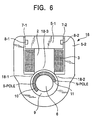
- Fig.6 is a sectional drawing view showing a second structure of an electromagnetic actuator according to the present invention.
- a yoke 5-2 faces at both ends thereof both ends of a yoke 5-1 via magnetic gaps 7-1 and 7-2.
- Hall sensors 8-1 and 8-2 are installed at both ends of the yoke 5-1.
- Hall sensors 8-1 and 8-2 detect a magnetic flux density which passes through the magnetic gap 7-1 and 7-2. As two Hall sensors 8-1 and 8-2 are provided, the flux density can precisely be detected even if one of them fails.
- An opening 9 is formed in a yoke 5, where a rotor 6 i. e.
- a movable member is inserted in the opening 9 without touching the inside wall of the opening 9 and is arranged such that rotor 6 faces to magnetic poles 18-1, 18-2 and 18-3.
- the rotor 6 is made of a magnetic material and magnetized so as to produce different magnetic poles on the surface thereof such as permanent magnets 10 and 11.
- the rotor 6 In this electromagnetic actuator 16 similar to the electromagnetic actuator 1 mentioned above, the rotor 6 always returns to a reference position when no power source current is supplied to the electromagnetic coil 3. When the electromagnetic coil 3 is supplied with a power source current, the rotor 6 rotates up to a predetermined angle.
- the rotation angle of the rotor 6 can be calculated by such a circuit as shown in Fig. 4.
- the magnetic flux density can be precisely detected to calculate the rotation angle of the rotor 6 by providing Hall sensors at both sides of the electromagnetic coil 3.
- Fig. 7 is a sectional view showing a third structure of an electromagnetic actuator according to the present invention.
- the counterparts of the devices shown in Fig. 2 and 7 are designated by the same reference numerals as each there.
- a magnetic gap 7 is disposed between a core section 2 and a yoke 5. Within the magnetic gap 7 is provided a Hall sensor 8 for detecting magnetic flux density which passes through the gap 7.
- a slide block 15 which is slidable along a supporting member (not shown) made of a magnetic material is provided in such a manner that slide block 15 does not contact to the yoke 5, while facing magnetic pole pieces 18-1, 18-2 and 18-3.
- the slide block 15 is equipped with permanent magnets 10 and 11.
- the slide block 15 When a current is not supplied from the power source to the electromagnetic coil 3, the slide block 15 is urged to take such a home position the magnetic flux formed by permanent magnet 10 and 11 distributes symmetrically on a plane of Fig. 7 while being urged to always return to the home position.
- a current is supplied from the power source to the electromagnetic coil 3
- the slide block 15 is caused to move up to a predetermined position.
- the position of this slide block 15 can be calculated by such a circuit as shown in Fig. 4.
- Fig. 8 shows a circuit diagram of an electromaguetic actuator according to the present invention that detects a rotation angle of a rotor.
- the counter parts of the devices shown in Fig. 4 and 8 are designated by the same reference numerals as each there.
- a drive current I emitted from a drive circuit 100 is supplied to a coil 3 in an electromagnetic actuator 1 and is converted into a voltage signal (referred to as a drive current voltage signal hereinafter) by means of a resistor 61 in an operation circuit 60.
- the drive current voltage signal is supplied to the positive and negative terminals of an operational amplifier 65 via resistors 62 and 63.
- the positive terminal of the operational amplifier 65 is connected to a power source 67 that supplies predetermined voltage of, for example, 2.5 (V), via a resistor 64.
- the negative terminal of the operational amplifier 65 is, on the other hand, connected to an output terminal of the operational amplifier 65 via a resistor 66.
- the output terminal of the operational amplifier 65 is connected to one port AD1 of an analog-digital converter 80.
- the voltage signal having a voltage value (referred to as a magnetic flux density voltage signal hereinafter) representing the magnetic flux density of the magnetic flux generated by the coil 3 is emitted from the Hall sensor 8 provided in the electromagnetic actuator 1.
- This magnetic flux density voltage signal is supplied respectively to positive and negative terminals of an operational amplifier 73 via resistors 71 and 72 in a subtraction circuit 70.
- the positive terminal of the operational amplifier 73 is connected to the output terminal of the operational amplifier 65 via a resistor 74.
- the negative terminal of the operational amplifier 73 is connected to the output terminal of the operational amplifier 73 via a resistor 75.
- the output terminal of operational amplifier 73 is connected to a port AD2 of the analog-digital converter 80.
- the operation circuit 70 amplifies the voltage signal representing a subtraction between the magnetic flux density voltage signal detected by the Hall sensor 8 and the drive current voltage signal emitted from the operational amplifier 65 at an amplification factor determined by resistors 71, 72, 74 and 75 to supply to the analog-digital converter 80.
- An analog-digital converter 80 is connected to a central processing unit (referred to as CPU hereinafter) 90.
- the analog-digital converter 80 supplies a sample value of the voltage subtraction V minus Vi to CPU 90 in response to a command from CPU 90, where Vi represents a sample voltage value of a drive current voltage signal and V represents a voltage value of the magnetic flux density voltage signal.
- the voltage change of the subtraction of voltage signal (V-Vi) can be controlled at a low level, even if the voltage value Vi of the drive current voltage signal changes largely. It is because the subtraction voltage signal is reduced by the drive current voltage signal Vi. Even when an amplification factor of subtraction voltage signal is raised in order to effectively use the resolution of the analog-digital converter 80, the subtraction voltage signal can fall within the input range, for example 0-5 volts, of the analog-digital converter 80.
- the analog-digital converter 80 can operate over a preferred range for the magnetic flux density voltage signal with suitable resolution and can precisely detect the present position of the rotor 6 i. e. the driven member. Such advantages are derived from the arrangement mentioned above which is much better than such a constitution that the magnetic flux density voltage signal is directly supplied to an analog-digital converter 80.
- a previous adjustment process can be preferably done by supplying the predetermined values of the drive current I.
- Those predetermined values are those corresponding to predetermined positions of the rotor 6, for example, fully-open and fully-closed positions of a throttle valve of an internal-combustion engine being linked to the rotor 6.
- the values of drive current I are detected at the respective positions mentioned above.
- the values of the drive current voltage signal Vi and the value of the subtraction voltage V-Vi shall be preferably memorized, for example, in a ROM (not shown) as a set of initial values (referred to as I, V0, and Vi0 hereinafter).
- a position of the driven member can be precisely detected while compensating the values of current I, the voltage V and the voltage Vi in comparison with the initial values of I0, V0 and Vi0 mentioned above.
- the electromagnetic actuator is free from influence of the changes in sensitivity of the Hall sensors and dispersions of resistors in the circuit while the adjustment can be done for the actuator.
- an electromagnetic actuator according to the present invention has been incorporated with the first structure of an electromagnetic actuator 1, the second structure of an electromagnetic actuator 16 and the third structure of an electromagnetic actuator 17 can be used for an electromagnetic actuator according to the present invention.
- the electromagnetic actuator according to the present invention detects the magnetic flux density at the magnetic gap provided within the magnetic flux formation section as mentioned above, it can precisely detect the density of the magnetic flux and the position of a driven member. Because of the magnetic flux density detection means being installed in the magnetic gap, it is unnecessary to change the drive mechanism design and the magnetic flux density detection means can be used even together with the drive mechanism that has a different structure. The voltage value of the voltage signal emitted from the magnetic flux density detection means can be obtained with suitable resolution and the present position of a driven member can be precisely detected.
Landscapes
- Engineering & Computer Science (AREA)
- Power Engineering (AREA)
- Microelectronics & Electronic Packaging (AREA)
- Reciprocating, Oscillating Or Vibrating Motors (AREA)
- Measurement Of Length, Angles, Or The Like Using Electric Or Magnetic Means (AREA)
- Transmission And Conversion Of Sensor Element Output (AREA)
Description
- The present invention relates to an electromagnetic actuator and, in particular, especially to an electromagnetic actuator which can drive a driven member while detecting a position of the driven member.
- An electromagnetic actuator which drives a driven member has needed a position sensor for detecting an actual position of the driven member which sensor is separate from the electromagnetic actuator itself. To solve this problem, as well as to make the costs lower and to save space, the applicant proposed such an electromagnetic actuator which involves a movable member as a driven member being driven while detecting the actual position of the movable member in Japanese Patent Kokai 8-275460. The outline of this apparatus is as shown in Fig. 1. In Fig. 1, an
electromagnetic coil 3 is wound around ayoke 5. A pair ofmagnetic poles yoke 5 are located to face each other via an air gap to distribute a magnetic flux thereby to form a magnetic field therebetween. Within the magnetic field between themagnetic poles rotor 6 made ofmagnetic component 103 provided with a pair ofpermanent magnets Hall sensor 8 which detects the magnetic flux density is provided in the proximity area betweenmagnetic poles rotor 6 up to a desired angular position by the varying strength of a magnetic field established by a magnetic flux formed inside theyoke 5, the magnetic flux being formed by supplying a source current to theelectromagnetic coil 3. - However, this type of electromagnetic actuator has such an inconvenience that the detection sensitivity of this type remains low because the
Hall sensor 8 detecting the rotation angle ofrotor 6 is located in the magnetic field formed by the magnetic flux distributed by themagnetic coil 3, and the density of magnetic flux passing through the Hall sensor is low. Moreover, there is another inconvenience that, freedom in design of a driving mechanism in the electromagnetic actuator is restricted in order to spare some space for a Hall sensor to be provided. Furthermore, there even happened that a Hall sensor could not be installed with the driving mechanism because of restrictions in structure of driving mechanism. - When, moreover, there adopted such a design that the voltage signal emitted from a Hall sensor is processed after detecting the sample value by a sampling circuit, that is, for example, a voltage signal is incorporated through the analog-digital conversion circuit and is processed based on the obtained sample value, a voltage transformation circuit is needed to transform the voltage signal received from a Hall sensor into a voltage signal having a voltage level appropriate to the input range of the sampling circuit. If the circuit is so composed as mentioned above, the amplification rate of the voltage transformation circuit is to be adjusted in accordance with the sensitivity of the Hall sensor or the dispersion of the resistance values of circuit components, thereby causing the costs to rise up or needing an improved accuracy in the adjustment.
- The present invention has been made to solve such problems mentioned above and to provide an electromagnetic actuator as defined in
claim 1 which can detect precisely the location of the driven member by detecting the density of magnetic flux where the density is high. The driving mechanism does not need the design change thereof. The position sensor is applicable for different structures of the driving mechanism. The actuator can detect precisely the position of the driven member by obtaining a voltage value of the voltage signal emitted from the Hall sensor with an appropriate resolution while being easily adjusted. - An electromagnetic actuator according to the present invention can precisely detect the position of a driven member since the magnetic flux density is detected at the magnetic gap provided within the magnetic flux forming means. Furthermore, with this arrangement it makes needless to change the design of the driving mechanism and enables this magnetic flux density detecting means to use together with different structure of a driving mechanism.
-
- Fig. 1 is a front view showing a conventional electromagnetic actuator;
- Fig. 2 is a sectional view showing a first structure of an electromagnetic actuator according to the present invention;
- Fig. 3 is an expanded perspective view showing an electromagnetic gap section of the electromagnetic actuator shown in Fig. 2;
- Fig. 4 is a circuit diagram showing a circuit including an electromagnetic actuator and detecting circuit for detecting a rotation angle of a rotor;
- Fig. 5 is a graph showing relations between a rotor rotational angle of an electromagnetic actuator and an output voltage of a Hall sensor shown in Fig. 2;
- Fig. 6 is a sectional view showing a second structure of an electromagnetic actuator according to the present invention;
- Fig. 7 is a sectional view showing a third structure of an electromagnetic actuator according to the present invention; and
- Fig. 8 is a circuit diagram of an electromagnetic actuator according to the present invention which receives both of a drive current voltage signal and of a difference between a voltage value of a flux-density voltage signal and a voltage value of a drive current voltage signal in the fourth embodiment.
-
- Description is made hereinafter for preferred embodiments of the present invention while referring to the drawings.
- Fig. 2 shows a first structure of an electromagnetic actuator according to the present invention.
- A
core section 2 which is a magnetic flux formation section of theelectromagnetic actuator 1 is provided with anelectromagnetic coil 3 wound therearound. Theelectromagnetic coil 3 is connected to a power source (not shown) and a current from the power source is supplied to theelectromagnetic coil 3. To one end of thecore section 2, anelectromagnetic component yoke 5 is connected, and the other end of thecore section 2 faces toward theyoke 5 via amagnetic gap 7. Within theyoke 5 is formed anopening 9 within which arotor 6 i. e. movable member is provided without touching the inside wall of opening 9 while facing magnetic pieces of 18-1 and 18-2. Therotor 6 is made of a magnetic material. The surface of therotor 6 is magnetized so as to produce different poles, for example suchpermanent magnets Permanent magnets permanents magnets yoke 5 at both sides of theopening 9 arenarrow areas areas yoke 5 is provided with aslot 14 near themagnetic gap 7 as shown, for example, in Fig. 3. AHall sensor 8 is to be provided at theslot 14 in order to detect a magnetic flux density passing through themagnetic gap 7. ThisHall sensor 8 produces a voltage signal representing the detected magnetic flux density. When, with the arrangements mentioned above, the power source current is supplied to theelectromagnetic coil 3, a magnetic flux is formed inside thecore section 2 and the formed magnetic flux produces a magnetic field in the space of theopening 9 of theyoke 5. - As the
magnetic gap 7 has relatively a large magnetic reluctance compared to the magnetic power ofpermanent magnets permanent magnets rotor 6 is made stable as long as no current is supplied to theelectromagnetic coil 3. When, therefore no current is supplied to theelectromagnetic coil 3, therotor 6 always returns to a predetermined reference position so as to take a stable state. When, on the other hand, a current is supplied to theelectromagnetic coil 3, the magnetic flux formed by theelectromagnetic coil 3 passes through themagnetic gap 7 so as to form a loop which passes through theyoke 5. In this instance, magnetic saturation arises only by a slight magnetic flux formed in themagnetic reluctance sections magnetic reluctance sections magnetic reluctance sections electromagnetic coil 3 increases. When, therefore a current is supplied to theelectromagnetic coil 3, a most part of magnetic flux generated by theelectromagnetic coil 3 is going to form the loop passing through theopening 9 where magnetic reluctance is low so that therotor 6 rotates up to the predetermined position. Theelectromagnetic actuator 1 drives a driven member connected with therotor 6, for example, such as a throttle valve provided at an intake system of an internal-combustion engine because of such rotation operation of therotor 6 as mentioned above. - Fig. 4 shows the electromagnetic actuator and a circuit for detecting a rotation angle of the rotor which does not form part of the present invention. Here, the same reference numerals are used for referring to counterparts shown in Fig. 2. One end of the output line of the
Hall sensor 8 is connected to a negative terminal of anoperational amplifier 25 via aresistor 21 of adifferential amplifier 20. The other output line of theHall sensor 8 is connected to a positive terminal of theoperational amplifier 25 viaresistors operational amplifier 25 is connected to the negative terminal of theoperational amplifier 25 via theresistor 22, and is also connected to the negative terminal of an operational amplifier 34 of anadder amplifier 30 via aresistor 32. - The
electromagnetic coil 3 has one end thereof connected to the power source (not shown) and the other end thereof connected to aresistor 40. A connecting point between theelectromagnetic coil 3 and theresistor 40 is connected to the negative terminal of an operational amplifier 34 via aresistor 31. Furthermore, the positive-electrode terminal of the operational amplifier 34 is grounded via theresistor 33. An output signal of the operational amplifier 34 is emitted through anoutput terminal 50. - Fig. 5 shows a relation between the rotation angle of the electromagnetic actuator and the output voltage of the Hall sensor shown in Fig. 2.
- As shown in Fig. 5, the relation between rotation angle and the output voltage V from the Hall sensor can be approximated, for example, by means of a primary function. When a current I supplied to the electromagnetic coil changes, the angle can be expressed as a primary function having the inclination but different values of at =0. These relations are obtained through a preparatory experiments while using an actual device and can be expressed, for example, with a relational formula like =Av+BI+C . Here, A, B, and C are constants, for example, the values of them being expressed by A= 2.98, B=-0.59, and C= 4.93.
- The
differential amplifier 20 and theadder amplifier 30 shown in Fig. 4 already mentioned above calculate such relational expression as mentioned above, and output the voltage value corresponding to the rotation angle of therotor 6. Therefore, the resistance values of the resistor 21-24 in thedifferential amplifier 20, of the resistors 31-33 in theadder amplifier 30 and of theresistor 40 are so selected as to realize the values of the constants A, B, and C mentioned above. - Fig.6 is a sectional drawing view showing a second structure of an electromagnetic actuator according to the present invention. Here, the same reference numerals are used for denoting counterparts of that shown in Fig. 2. A yoke 5-2 faces at both ends thereof both ends of a yoke 5-1 via magnetic gaps 7-1 and 7-2. Hall sensors 8-1 and 8-2 are installed at both ends of the yoke 5-1. Hall sensors 8-1 and 8-2 detect a magnetic flux density which passes through the magnetic gap 7-1 and 7-2. As two Hall sensors 8-1 and 8-2 are provided, the flux density can precisely be detected even if one of them fails. An
opening 9 is formed in ayoke 5, where arotor 6 i. e. a movable member is inserted in theopening 9 without touching the inside wall of theopening 9 and is arranged such thatrotor 6 faces to magnetic poles 18-1, 18-2 and 18-3. Therotor 6 is made of a magnetic material and magnetized so as to produce different magnetic poles on the surface thereof such aspermanent magnets electromagnetic actuator 16 similar to theelectromagnetic actuator 1 mentioned above, therotor 6 always returns to a reference position when no power source current is supplied to theelectromagnetic coil 3. When theelectromagnetic coil 3 is supplied with a power source current, therotor 6 rotates up to a predetermined angle. The rotation angle of therotor 6 can be calculated by such a circuit as shown in Fig. 4. - In the
electromagnetic actuator 1 shown in Fig. 2 even if either of the Hall sensors fails, the magnetic flux density can be precisely detected to calculate the rotation angle of therotor 6 by providing Hall sensors at both sides of theelectromagnetic coil 3. - Fig. 7 is a sectional view showing a third structure of an electromagnetic actuator according to the present invention. The counterparts of the devices shown in Fig. 2 and 7 are designated by the same reference numerals as each there.
- A
magnetic gap 7 is disposed between acore section 2 and ayoke 5. Within themagnetic gap 7 is provided aHall sensor 8 for detecting magnetic flux density which passes through thegap 7. Aslide block 15 which is slidable along a supporting member (not shown) made of a magnetic material is provided in such a manner that slideblock 15 does not contact to theyoke 5, while facing magnetic pole pieces 18-1, 18-2 and 18-3. Theslide block 15 is equipped withpermanent magnets - When a current is not supplied from the power source to the
electromagnetic coil 3, theslide block 15 is urged to take such a home position the magnetic flux formed bypermanent magnet electromagnetic coil 3, theslide block 15 is caused to move up to a predetermined position. The position of thisslide block 15 can be calculated by such a circuit as shown in Fig. 4. - Fig. 8 shows a circuit diagram of an electromaguetic actuator according to the present invention that detects a rotation angle of a rotor. The counter parts of the devices shown in Fig. 4 and 8 are designated by the same reference numerals as each there. A drive current I emitted from a
drive circuit 100 is supplied to acoil 3 in anelectromagnetic actuator 1 and is converted into a voltage signal (referred to as a drive current voltage signal hereinafter) by means of aresistor 61 in anoperation circuit 60. The drive current voltage signal is supplied to the positive and negative terminals of anoperational amplifier 65 viaresistors operational amplifier 65 is connected to apower source 67 that supplies predetermined voltage of, for example, 2.5 (V), via aresistor 64. The negative terminal of theoperational amplifier 65 is, on the other hand, connected to an output terminal of theoperational amplifier 65 via aresistor 66. The output terminal of theoperational amplifier 65 is connected to one port AD1 of an analog-digital converter 80. After theoperation circuit 60 converts the drive current I supplied to thecoil 3 into a drive current voltage signal by using theresistor 61, it amplifies the drive current voltage signal at an amplification factor determined byresistors digital converter 80. - The voltage signal having a voltage value (referred to as a magnetic flux density voltage signal hereinafter) representing the magnetic flux density of the magnetic flux generated by the
coil 3 is emitted from theHall sensor 8 provided in theelectromagnetic actuator 1. This magnetic flux density voltage signal is supplied respectively to positive and negative terminals of anoperational amplifier 73 viaresistors subtraction circuit 70. The positive terminal of theoperational amplifier 73 is connected to the output terminal of theoperational amplifier 65 via aresistor 74. The negative terminal of theoperational amplifier 73 is connected to the output terminal of theoperational amplifier 73 via aresistor 75. The output terminal ofoperational amplifier 73 is connected to a port AD2 of the analog-digital converter 80. Theoperation circuit 70 amplifies the voltage signal representing a subtraction between the magnetic flux density voltage signal detected by theHall sensor 8 and the drive current voltage signal emitted from theoperational amplifier 65 at an amplification factor determined byresistors digital converter 80. - An analog-
digital converter 80 is connected to a central processing unit (referred to as CPU hereinafter) 90. The analog-digital converter 80 supplies a sample value of the voltage subtraction V minus Vi toCPU 90 in response to a command fromCPU 90, where Vi represents a sample voltage value of a drive current voltage signal and V represents a voltage value of the magnetic flux density voltage signal.CPU 90 calculates the voltage value V of a magnetic flux density voltage signal by an additional processing of these sample values and calculates the drive current I from the voltage value Vi representing the drive current and thenCPU 90 calculates a rotation angle of arotor 6 on the basis of a formula =AV+BI+C as mentioned above while using the resultant voltage V and drive current I. - Since the drive current voltage signal Vi and of the subtraction voltage signal having the voltage value V minus Vi are respectively supplied to the analog-
digital converter 80 as mentioned above, the voltage change of the subtraction of voltage signal (V-Vi) can be controlled at a low level, even if the voltage value Vi of the drive current voltage signal changes largely. It is because the subtraction voltage signal is reduced by the drive current voltage signal Vi. Even when an amplification factor of subtraction voltage signal is raised in order to effectively use the resolution of the analog-digital converter 80, the subtraction voltage signal can fall within the input range, for example 0-5 volts, of the analog-digital converter 80. The analog-digital converter 80 can operate over a preferred range for the magnetic flux density voltage signal with suitable resolution and can precisely detect the present position of therotor 6 i. e. the driven member. Such advantages are derived from the arrangement mentioned above which is much better than such a constitution that the magnetic flux density voltage signal is directly supplied to an analog-digital converter 80. - When the electromagnetic actuator is to be adjusted, a previous adjustment process can be preferably done by supplying the predetermined values of the drive current I. Those predetermined values are those corresponding to predetermined positions of the
rotor 6, for example, fully-open and fully-closed positions of a throttle valve of an internal-combustion engine being linked to therotor 6. The values of drive current I are detected at the respective positions mentioned above. The values of the drive current voltage signal Vi and the value of the subtraction voltage V-Vi shall be preferably memorized, for example, in a ROM (not shown) as a set of initial values (referred to as I, V0, and Vi0 hereinafter). When the electromagnetic actuator is in use, a position of the driven member can be precisely detected while compensating the values of current I, the voltage V and the voltage Vi in comparison with the initial values of I0, V0 and Vi0 mentioned above. The electromagnetic actuator is free from influence of the changes in sensitivity of the Hall sensors and dispersions of resistors in the circuit while the adjustment can be done for the actuator. - Although the circuit of an electromagnetic actuator according to the present invention as mentioned above, has been incorporated with the first structure of an
electromagnetic actuator 1, the second structure of anelectromagnetic actuator 16 and the third structure of anelectromagnetic actuator 17 can be used for an electromagnetic actuator according to the present invention. - Since the electromagnetic actuator according to the present invention detects the magnetic flux density at the magnetic gap provided within the magnetic flux formation section as mentioned above, it can precisely detect the density of the magnetic flux and the position of a driven member. Because of the magnetic flux density detection means being installed in the magnetic gap, it is unnecessary to change the drive mechanism design and the magnetic flux density detection means can be used even together with the drive mechanism that has a different structure. The voltage value of the voltage signal emitted from the magnetic flux density detection means can be obtained with suitable resolution and the present position of a driven member can be precisely detected.
Claims (3)
- An electromagnetic actuator (1, 16, 17) which comprises:said calculating means including:a magnetic path component which is composed of a magnetic flux formation section (2) provided with an electromagnetic coil (3) and of a magnetic field formation part (5) which causes a magnetic flux to form a magnetic field between a plurality of magnetic poles (18-1, 18-2).a movable member (6) which is movably disposed within said magnetic field and has magnetized surfaces (10, 11) differently magnetized from each other and corresponding to the magnetic poles;said magnetic field formation section having a plurality of magnetic poles corresponding to the magnetized surfaces of said movable member so as to drive said movable member, andsaid magnetic path component having a magnetic gap (7) at a magnetic path connecting said magnetic flux formation section with said magnetic field formation part;magnetic flux density detecting means (8) installed within said magnetic gap (7), for detecting a magnetic flux density within said magnetic gap so as to generate a magnetic flux density voltage signal;detecting means (30, 40) for detecting a magnitude of an electric current flowing through said electromagnetic coil (3); andcalculating means for calculating a position of said movable member on the basis of the detected magnetic flux density and on the detected magnitude of the current;current voltage transformation means (60) for producing a current representing signal having a voltage value representing a value of said electric current;subtracting means (70) for producing a subtraction signal having a voltage representing a difference in voltage between said current representing signal and said magnetic flux density voltage signal; anda calculator (80, 90) for calculating said position of the movable member on the basis of said current representing signal and said subtraction signal.
- An electromagnetic actuator as defined in claim 1, in which
said magnetic field formation section of said magnetic path section has an opening (9) formed within said magnetic path section with a continuous peripheral wall, through which said movable member is inserted without contacting with said peripheral wall of said opening (9). - An electromagnetic actuator as defined in claim 1, in which said calculation means further comprises:sampling means for sampling the respective ones of said current representing signal and said subtraction signal; andadder means for adding a sample value of said current representing signal and a sample value of said subtraction signal.
Applications Claiming Priority (4)
| Application Number | Priority Date | Filing Date | Title |
|---|---|---|---|
| JP9510298 | 1998-04-08 | ||
| JP9510298 | 1998-04-08 | ||
| JP4322999 | 1999-02-22 | ||
| JP11043229A JPH11356029A (en) | 1998-04-08 | 1999-02-22 | Electromagnetic actuator |
Publications (3)
| Publication Number | Publication Date |
|---|---|
| EP0949744A2 EP0949744A2 (en) | 1999-10-13 |
| EP0949744A3 EP0949744A3 (en) | 2000-12-06 |
| EP0949744B1 true EP0949744B1 (en) | 2005-06-08 |
Family
ID=26382982
Family Applications (1)
| Application Number | Title | Priority Date | Filing Date |
|---|---|---|---|
| EP99106875A Expired - Lifetime EP0949744B1 (en) | 1998-04-08 | 1999-04-07 | Electromagnetic actuator with function detecting position of driven member |
Country Status (5)
| Country | Link |
|---|---|
| US (1) | US6437962B1 (en) |
| EP (1) | EP0949744B1 (en) |
| JP (1) | JPH11356029A (en) |
| KR (1) | KR19990083064A (en) |
| DE (1) | DE69925666T2 (en) |
Families Citing this family (9)
| Publication number | Priority date | Publication date | Assignee | Title |
|---|---|---|---|---|
| US6921999B1 (en) * | 1999-01-21 | 2005-07-26 | Stridsberg Innovation Ab | Electric motor |
| FR2791487B1 (en) * | 1999-03-26 | 2004-09-03 | Moving Magnet Tech | METHOD FOR DETERMINING THE POSITION OF A MOBILE MEMBER IN AT LEAST ONE MAIN INTERFER OF AN ELECTROMAGNETIC ACTUATOR |
| WO2003098147A1 (en) * | 2002-05-15 | 2003-11-27 | American Electronic Components, Inc. | Through the hole rotary position sensor |
| JP4233958B2 (en) * | 2003-08-29 | 2009-03-04 | 株式会社日本自動車部品総合研究所 | Rotation angle detector |
| WO2005050077A1 (en) * | 2003-11-18 | 2005-06-02 | Ecolab, Inc. | Apparatus for the supply or handling of products and sensor means for such apparatus |
| JP3952207B2 (en) * | 2004-12-15 | 2007-08-01 | 株式会社タムロン | Actuator and lens unit and camera provided with the same |
| WO2007108063A1 (en) * | 2006-03-17 | 2007-09-27 | Mitsubishi Denki Kabushiki Kaisha | State grasping device and open/closure controller having this state grasping device |
| GB2468311B (en) * | 2009-03-03 | 2014-09-17 | Dyson Technology Ltd | Positioning of a Hall-effect sensor within an electric machine |
| DE102017200828B4 (en) | 2017-01-19 | 2018-09-20 | Hochschule Heilbronn | Method and arrangement for determining the armature position of an electromagnet |
Family Cites Families (14)
| Publication number | Priority date | Publication date | Assignee | Title |
|---|---|---|---|---|
| DE2019345C3 (en) * | 1970-04-22 | 1982-12-09 | Voith Getriebe Kg, 7920 Heidenheim | Arrangement for influencing the excitation current of a direct current electromagnet used as a drive for solenoid valves |
| US4434450A (en) * | 1981-12-21 | 1984-02-28 | General Electric Company | Controlled flux contactor |
| US4659969A (en) * | 1984-08-09 | 1987-04-21 | Synektron Corporation | Variable reluctance actuator having position sensing and control |
| JPS61208641A (en) * | 1985-03-13 | 1986-09-17 | Olympus Optical Co Ltd | Optical information recording and reproducing device |
| US4656400A (en) * | 1985-07-08 | 1987-04-07 | Synektron Corporation | Variable reluctance actuators having improved constant force control and position-sensing features |
| US5003211A (en) * | 1989-09-11 | 1991-03-26 | The United States Of America As Represented By The Administrator Of The National Aeronautics And Space Administration | Permanent magnet flux-biased magnetic actuator with flux feedback |
| US5481187A (en) * | 1991-11-29 | 1996-01-02 | Caterpillar Inc. | Method and apparatus for determining the position of an armature in an electromagnetic actuator |
| US5164668A (en) * | 1991-12-06 | 1992-11-17 | Honeywell, Inc. | Angular position sensor with decreased sensitivity to shaft position variability |
| US5264896A (en) * | 1992-05-18 | 1993-11-23 | Eastman Kodak Company | Continuously variable electronically actuated shuttering system |
| WO1994020767A1 (en) * | 1993-03-08 | 1994-09-15 | Noise Cancellation Technologies, Inc. | Methods and apparatus for closed-loop control of magnetic bearings |
| DE19501766A1 (en) * | 1995-01-21 | 1996-07-25 | Bosch Gmbh Robert | Control of proportional solenoid with movable element |
| DE19505219A1 (en) * | 1995-02-16 | 1996-08-22 | Juergen Weimer | Appts recognising position of electromagnetic adjusters |
| JP3472378B2 (en) | 1995-03-29 | 2003-12-02 | 株式会社ミクニ | Rotary solenoid position detector |
| US5787915A (en) * | 1997-01-21 | 1998-08-04 | J. Otto Byers & Associates | Servo positioning system |
-
1999
- 1999-02-22 JP JP11043229A patent/JPH11356029A/en active Pending
- 1999-04-06 US US09/286,821 patent/US6437962B1/en not_active Expired - Fee Related
- 1999-04-07 DE DE69925666T patent/DE69925666T2/en not_active Expired - Fee Related
- 1999-04-07 EP EP99106875A patent/EP0949744B1/en not_active Expired - Lifetime
- 1999-04-08 KR KR1019990012423A patent/KR19990083064A/en not_active Ceased
Also Published As
| Publication number | Publication date |
|---|---|
| JPH11356029A (en) | 1999-12-24 |
| EP0949744A3 (en) | 2000-12-06 |
| EP0949744A2 (en) | 1999-10-13 |
| US6437962B1 (en) | 2002-08-20 |
| DE69925666D1 (en) | 2005-07-14 |
| DE69925666T2 (en) | 2006-06-29 |
| KR19990083064A (en) | 1999-11-25 |
Similar Documents
| Publication | Publication Date | Title |
|---|---|---|
| JP2943657B2 (en) | Control device for salient pole type permanent magnet motor | |
| EP0949744B1 (en) | Electromagnetic actuator with function detecting position of driven member | |
| US8294317B2 (en) | Unidirectionally-energized brushless DC motor including AC voltage output winding and motor system | |
| EP1120626A3 (en) | Angular position measuring device | |
| JPH09231889A (en) | Position detecting sensor | |
| WO2001095348A1 (en) | Electromagnetic actuator and valve driver and position or speed sensor comprising it | |
| CN110880838A (en) | Device and method for detecting temperature of permanent magnet of rotor of permanent magnet synchronous motor | |
| JPS6411845B2 (en) | ||
| EP1176325A2 (en) | Magnetic bearing apparatus | |
| JPS55106074A (en) | Moving-coil type linear motor | |
| EP0360166A3 (en) | Electromagnetic force sensor | |
| CN216482797U (en) | Contactless speed regulator based on linear Hall induction | |
| US20020078748A1 (en) | Circuit arrangement for evaluating an acceleration sensor using the Ferraris principle | |
| JPH11202036A (en) | Magnetic sensor | |
| JPS6143340Y2 (en) | ||
| JPH08122011A (en) | Magnetic angle detection apparatus | |
| JPH05248407A (en) | Control method and device for linear actuator | |
| JP2574367Y2 (en) | Linear actuator | |
| JP2558813Y2 (en) | Speed control device for linear DC motor | |
| JP2583913Y2 (en) | Magnetic bearing control device | |
| JPH0715937A (en) | Variable spring-constant linear actuator | |
| JPS5920746Y2 (en) | position detection device | |
| JPH0566102A (en) | Position detector | |
| JPH0926304A (en) | Permanent magnet-type angle-of-rotation detector | |
| JPH1052019A (en) | Electromagnetic actuator |
Legal Events
| Date | Code | Title | Description |
|---|---|---|---|
| PUAI | Public reference made under article 153(3) epc to a published international application that has entered the european phase |
Free format text: ORIGINAL CODE: 0009012 |
|
| AK | Designated contracting states |
Kind code of ref document: A2 Designated state(s): DE FR GB IT NL |
|
| AX | Request for extension of the european patent |
Free format text: AL;LT;LV;MK;RO;SI |
|
| PUAL | Search report despatched |
Free format text: ORIGINAL CODE: 0009013 |
|
| AK | Designated contracting states |
Kind code of ref document: A3 Designated state(s): AT BE CH CY DE DK ES FI FR GB GR IE IT LI LU MC NL PT SE |
|
| AX | Request for extension of the european patent |
Free format text: AL;LT;LV;MK;RO;SI |
|
| RIC1 | Information provided on ipc code assigned before grant |
Free format text: 7H 01F 7/18 A, 7H 02K 11/00 B, 7H 02K 26/00 B, 7G 01D 5/14 B |
|
| 17P | Request for examination filed |
Effective date: 20010206 |
|
| AKX | Designation fees paid |
Free format text: DE FR GB IT NL |
|
| 17Q | First examination report despatched |
Effective date: 20031128 |
|
| GRAP | Despatch of communication of intention to grant a patent |
Free format text: ORIGINAL CODE: EPIDOSNIGR1 |
|
| GRAS | Grant fee paid |
Free format text: ORIGINAL CODE: EPIDOSNIGR3 |
|
| GRAA | (expected) grant |
Free format text: ORIGINAL CODE: 0009210 |
|
| AK | Designated contracting states |
Kind code of ref document: B1 Designated state(s): DE FR GB IT NL |
|
| PG25 | Lapsed in a contracting state [announced via postgrant information from national office to epo] |
Ref country code: NL Free format text: LAPSE BECAUSE OF FAILURE TO SUBMIT A TRANSLATION OF THE DESCRIPTION OR TO PAY THE FEE WITHIN THE PRESCRIBED TIME-LIMIT Effective date: 20050608 Ref country code: IT Free format text: LAPSE BECAUSE OF FAILURE TO SUBMIT A TRANSLATION OF THE DESCRIPTION OR TO PAY THE FEE WITHIN THE PRESCRIBED TIME-LIMIT;WARNING: LAPSES OF ITALIAN PATENTS WITH EFFECTIVE DATE BEFORE 2007 MAY HAVE OCCURRED AT ANY TIME BEFORE 2007. THE CORRECT EFFECTIVE DATE MAY BE DIFFERENT FROM THE ONE RECORDED. Effective date: 20050608 |
|
| REG | Reference to a national code |
Ref country code: GB Ref legal event code: FG4D |
|
| REF | Corresponds to: |
Ref document number: 69925666 Country of ref document: DE Date of ref document: 20050714 Kind code of ref document: P |
|
| NLV1 | Nl: lapsed or annulled due to failure to fulfill the requirements of art. 29p and 29m of the patents act | ||
| ET | Fr: translation filed | ||
| PLBE | No opposition filed within time limit |
Free format text: ORIGINAL CODE: 0009261 |
|
| STAA | Information on the status of an ep patent application or granted ep patent |
Free format text: STATUS: NO OPPOSITION FILED WITHIN TIME LIMIT |
|
| 26N | No opposition filed |
Effective date: 20060309 |
|
| PGFP | Annual fee paid to national office [announced via postgrant information from national office to epo] |
Ref country code: DE Payment date: 20070405 Year of fee payment: 9 |
|
| PGFP | Annual fee paid to national office [announced via postgrant information from national office to epo] |
Ref country code: GB Payment date: 20070404 Year of fee payment: 9 |
|
| PGFP | Annual fee paid to national office [announced via postgrant information from national office to epo] |
Ref country code: FR Payment date: 20070411 Year of fee payment: 9 |
|
| GBPC | Gb: european patent ceased through non-payment of renewal fee |
Effective date: 20080407 |
|
| PG25 | Lapsed in a contracting state [announced via postgrant information from national office to epo] |
Ref country code: DE Free format text: LAPSE BECAUSE OF NON-PAYMENT OF DUE FEES Effective date: 20081101 |
|
| REG | Reference to a national code |
Ref country code: FR Ref legal event code: ST Effective date: 20081231 |
|
| PG25 | Lapsed in a contracting state [announced via postgrant information from national office to epo] |
Ref country code: FR Free format text: LAPSE BECAUSE OF NON-PAYMENT OF DUE FEES Effective date: 20080430 |
|
| PG25 | Lapsed in a contracting state [announced via postgrant information from national office to epo] |
Ref country code: GB Free format text: LAPSE BECAUSE OF NON-PAYMENT OF DUE FEES Effective date: 20080407 |