EP0949743A2 - Elektrische Maschine, insbesondere für Fahrstuhlantrieb - Google Patents
Elektrische Maschine, insbesondere für Fahrstuhlantrieb Download PDFInfo
- Publication number
- EP0949743A2 EP0949743A2 EP99106572A EP99106572A EP0949743A2 EP 0949743 A2 EP0949743 A2 EP 0949743A2 EP 99106572 A EP99106572 A EP 99106572A EP 99106572 A EP99106572 A EP 99106572A EP 0949743 A2 EP0949743 A2 EP 0949743A2
- Authority
- EP
- European Patent Office
- Prior art keywords
- stator
- electrical machine
- external rotor
- machine according
- braking device
- Prior art date
- Legal status (The legal status is an assumption and is not a legal conclusion. Google has not performed a legal analysis and makes no representation as to the accuracy of the status listed.)
- Withdrawn
Links
- 239000002904 solvent Substances 0.000 claims description 9
- 238000004804 winding Methods 0.000 claims description 9
- 230000005540 biological transmission Effects 0.000 claims description 6
- 238000003825 pressing Methods 0.000 claims description 4
- 238000012546 transfer Methods 0.000 claims description 3
- 230000005674 electromagnetic induction Effects 0.000 claims description 2
- 238000010276 construction Methods 0.000 abstract 1
- 238000011109 contamination Methods 0.000 abstract 1
- 238000013461 design Methods 0.000 description 4
- 238000003860 storage Methods 0.000 description 4
- 238000001816 cooling Methods 0.000 description 3
- 230000001960 triggered effect Effects 0.000 description 2
- 238000005299 abrasion Methods 0.000 description 1
- 238000006073 displacement reaction Methods 0.000 description 1
- 238000009826 distribution Methods 0.000 description 1
- 230000000694 effects Effects 0.000 description 1
- 230000017525 heat dissipation Effects 0.000 description 1
- 238000007373 indentation Methods 0.000 description 1
- 238000012423 maintenance Methods 0.000 description 1
- 238000004519 manufacturing process Methods 0.000 description 1
- 239000000463 material Substances 0.000 description 1
- 238000000034 method Methods 0.000 description 1
- 229910001172 neodymium magnet Inorganic materials 0.000 description 1
- 238000013021 overheating Methods 0.000 description 1
- 239000002245 particle Substances 0.000 description 1
- 230000001681 protective effect Effects 0.000 description 1
- 238000005096 rolling process Methods 0.000 description 1
- 238000000926 separation method Methods 0.000 description 1
- 239000007858 starting material Substances 0.000 description 1
- 238000012549 training Methods 0.000 description 1
Images

Classifications
-
- H—ELECTRICITY
- H02—GENERATION; CONVERSION OR DISTRIBUTION OF ELECTRIC POWER
- H02K—DYNAMO-ELECTRIC MACHINES
- H02K7/00—Arrangements for handling mechanical energy structurally associated with dynamo-electric machines, e.g. structural association with mechanical driving motors or auxiliary dynamo-electric machines
- H02K7/10—Structural association with clutches, brakes, gears, pulleys or mechanical starters
- H02K7/102—Structural association with clutches, brakes, gears, pulleys or mechanical starters with friction brakes
- H02K7/1021—Magnetically influenced friction brakes
- H02K7/1023—Magnetically influenced friction brakes using electromagnets
- H02K7/1025—Magnetically influenced friction brakes using electromagnets using axial electromagnets with generally annular air gap
-
- H—ELECTRICITY
- H02—GENERATION; CONVERSION OR DISTRIBUTION OF ELECTRIC POWER
- H02K—DYNAMO-ELECTRIC MACHINES
- H02K7/00—Arrangements for handling mechanical energy structurally associated with dynamo-electric machines, e.g. structural association with mechanical driving motors or auxiliary dynamo-electric machines
- H02K7/10—Structural association with clutches, brakes, gears, pulleys or mechanical starters
Definitions
- the invention relates to an electrical machine, in particular for an elevator drive, with a fixed one internal stator and one essentially the machine housing forming rotating external rotor, at least partially overlaps the stator and in the outer area of it axial expansion is supported, stator and external rotor via a radial separating, but in the axial direction running air gap in electromagnetically induced Connected to each other (radial field motor).
- EP 631 967 describes a traction sheave elevator which has a very flat engine.
- the Stator the machine housing with a radially inner one Stator coil, the elevator cables on the circumference of the rotor are stored.
- the runner has only one side Stock on.
- a flat drive engine designed as a disc motor, in which the elevator ropes on one inside the rotor spool on the suspended inside the engine part attached drive pulley are.
- the object of the invention is an electrical machine especially for an elevator drive, to create the Avoids problems of the prior art, especially one increased operational safety and reduced maintenance requirements guaranteed in a compact design and is versatile.
- the rotating one external runner has the advantage that it for improved cooling swirls cooling air itself.
- One in the machine housing arranged braking device is both protected against damage as well as pollution.
- Prefers the braking device is outside of an engine part that in particular the cylindrical one surrounded by the air gap May include space. Due to the spatial separation of the braking device from the engine part there is greater scope created for the braking device and their Accessibility improved. In addition, the engine part better against abrasion particles of the braking device or the like. to be protected.
- the braking device is particularly preferred in the area of a or radially within a coupled with the external rotor Driving wheel arranged to drive the rope, the braking device directly or indirectly partially with the driving wheel can be connected.
- the brake can be directly on the driving wheel be supported and forces generated when braking between the moving elevator car and the fixed mounting of the Machine transferred.
- the braking device can have braking surfaces, each are assigned to the stator and the external rotor, preferably each in at least four levels for the stator and external rotor.
- the braking surfaces can advantageously at least partially be movable or movable, in particular by Brake pressure or a pressing force in the axial direction of the Machine can be pressed against each other.
- the Braking surfaces can be moved over a certain range, especially in the axial direction. At least they can partially supported or stored freely movable and in separated state a certain distance from each have corresponding surface.
- the braking surfaces of the stator and / or the are preferred Outer rotor essentially running in the circumferential direction formed with circular ring surfaces, the circular rings in particular be divided into several circular ring sectors can. These can each be approximately the same size and at a particularly preferred embodiment of the invention independently from each other in the area of the same braking surface be movable. This enables a division, for example the braking device in two or more parts, individually or can be operated in groups.
- the braking surfaces on annular disks can be particularly preferred be arranged, preferably two braking surfaces a circular washer on the front and back can be trained.
- a preferred embodiment can provide that several circular washers Stator and external rotor alternately interlocking as Disc brakes are formed, preferably at least an annular disc is axially firmly supported.
- a support on the stator is preferred, this Fixed circular ring disc at one end of the multi-disc brake can be arranged and only on the to Provide the multi-disc brake side with a braking surface is. This means that the multi-disc brake is only required from one side pressure to be exerted.
- An actuator for the braking device is preferably arranged on the stator, it preferably a closing device for closing the braking device, especially by exerting the pressure, and at least one Have release device for releasing the braking device can.
- These devices preferably each comprise closing elements and / or release elements.
- the Closing device at least one elastic mechanical Locking element for applying the pressure force. Whose Direction of action advantageously runs axially and in particular through the braking surfaces to the contact pressure as possible bring evenly distributed on the braking surfaces.
- a design of the closing elements is particularly advantageous viewed as a coil spring or coil spring.
- the Safety function of the braking device can be improved when the locking device or the locking elements exert a permanent pressure force on the braking device, so that, for example, springs are permanently biased System against the braking surfaces.
- For better Distribution of the pressure force can be in several closing elements Provided evenly distributed circumferential direction, and their directions of action, in particular through the external Area of the braking surfaces of the stator. With divided Braking surfaces is preferably one closing element per segment available.
- the release device can have at least one release element, preferably an electromechanical release element, the can be designed as an electromagnet.
- a preferred one Training looks essentially circumferential wound and / or extending in the axial direction before, preferably at least a short distance from each other a locking element of the locking device can. It can be either a rotating coil or two separate, parallel rotating coils are available be.
- At least one release element preferably surrounds at least a closing element, in a particularly preferred embodiment all locking elements are surrounded by release elements. This enables a more direct transfer of the release force from the release elements on the closing elements, preferably over a pressure surface, so that in the normal operating state Machine as a result of a lack of pressure force the braking surfaces are spaced from each other and no braking torque apply.
- additional Solvents for releasing the braking device may be provided, which are preferably designed as mechanical solvents and in particular have a power transmission element can transmit forces in at least one longitudinal direction can.
- additional ones are particularly preferred Solvent in an electromechanical release device because for example, the electrically operated in the event of a power failure Release device fails, the braking device is activated and the brake closes.
- to release the brake can be mechanical, for example manually operated, Solvents particularly advantageous.
- the power transmission element can be designed as a Bowden cable, which by a Axial bore in the inner stator shaft from the Machine can be led out for external actuation.
- a deflection device can be provided, preferably at least one deflection roller or a deflection lever. These can allow the outside of the Brake device attacking power transmission element in the lead the central area of the machine out of it.
- At least part of the generation of electromagnetic Induction in the air gap can be done through an electrical coil take place, which is arranged in particular on the stator, preferably as a stator winding, the longitudinal axis of this Coil runs in the axial direction of the machine.
- a preferred one Number of poles is 24 or more.
- a power supply the stator coil or stator winding can pass through the stator run, in particular through a stator shaft, in the preferably a channel for cables and possibly others Supply lines is formed, which in this way from the Machine are brought out.
- the machine can with at least be provided with a permanent magnet, for example made of NdFeB material, whereby it preferably has a low radial Has thickness.
- a permanent magnet for example made of NdFeB material, whereby it preferably has a low radial Has thickness.
- Mass can be at least one permanent magnet on the Outrunner be arranged. In this way, the crowd the outer rotor, which has a larger radius than that internal stator can be kept low. For manufacturing reasons it is preferably divided into smaller sections, which are distributed in a subsequent arrangement.
- the Driving wheel as rope drum with several external and in Circumferential grooves for receiving such as Drive the rope or an elevator attached to it be formed by friction.
- the cable drum is attached directly to the electrical machine, especially on the external rotor without a gear or the like To be free in the dimensioning of the diameter it can be axially offset from the motor part or from the space surrounding the air gap. Especially it may have a smaller diameter than the air gap have, which results in a higher engine speed realize at a certain elevator speed leaves.
- the cable drum can be on a section of the external rotor or its housing can be placed, preferably on one end of the outrunner.
- the cable drum from the outer rotor be formed, in particular from a part its outer surface, either from the engine part or preferably from one end of the outrunner.
- the external rotor is particularly preferred the area surrounded by the cable drum, in particular outside the engine part.
- Such a direct one Support of the rope drum on the bearing and thus the Stator is particularly good at those caused by the rope Take up forces in the radial direction so that it is neither too denting the rope drum to decenter it the machine can come.
- the external rotor is particularly preferred stored in the area of its two ends, in particular with rolling bearings, with an attachment of the bearings to the two Ends of the stator is particularly preferred.
- a circumferential circumferential Teeth On the external rotor, especially on the drive wheel adjacent area, a circumferential circumferential Teeth, preferably a ring gear, may be provided.
- the Teeth themselves can run axially or slightly obliquely axially.
- the ring gear can be formed on the outer rotor or as separate component can be attached.
- To the gearing is preferably via an axially movable gear or pinion
- Emergency drive motor can be coupled, for example via a Magnet drive, similar to a starter pinion for one Car engine.
- the emergency drive motor which is preferably used as a DC motor is carried out, for example, for a so-called emergency or evacuation drive its driving force on the external rotor or drives the machine.
- the emergency drive motor can be via a battery or an accumulator be fed, whereby its performance, possibly in the event of overload, only be designed for short operation can.
- Another field of application of the invention can be found in Field of printing presses, especially as a drive for pressure waves.
- FIG. 1 shows an electrical machine according to the invention 11, which consists of a fixed stator 12 and one around the Stator rotating outer rotor 13 is made. 1 is the stator 12 at its two outer ends on two bearing blocks 14 held, by means of which it is mounted on a carrier or a carrier plate can be attached, preferably by Screw connection. Of course they all offer themselves Storage options, deviating from that shown in Fig. 1 shown.
- the outer rotor is 13 rotatably supported on the stator 12.
- the right warehouse 16 extends from a front housing shell 17 first radially outwards, then with an approximately rectangular one Bend the length of the outer rotor a little in Direction to the right bearing block 14 so far until it almost reaches it and from then on with you Another kink in the radial direction up to the outer diameter extends.
- the front housing shell 17 with a rear housing shell 18 through the front Housing screws 19 connected.
- the rear case shell 18 extends across the stator 12 in the axial direction over about two thirds of the length of the external rotor 13, and then to pass into a diameter constriction 20. From the left end the diameter constriction 20 runs the housing shell radially inwards and opens into a receptacle 21 for the left bearing 16.
- Rope drum 23 By means of a radially inward reaching paragraph 24 it lies in a circumferential corner groove the diameter constriction 20, with the end face bores for receiving cable drum screws 25, which are in axial Engage in the rear housing shell 18 in the direction having.
- Rope drum 23 and rear housing shell 18 the outer rotor 13 approximately flush from.
- the cable drum 23 has several provided in the circumferential direction grooves 27 which for Inclusion of a rope are provided on which an elevator car is attached.
- stator 12 has its ends are held in the bearing blocks 14, in the middle area a radially projecting carrier 29 on its External cross section carries the stator winding 30.
- the stator winding 30 is arranged in a laminated core 31, which by means of a continuous screw 32 with a radial protruding fastening projection 33 of the carrier 29 screwed is.
- the screw 32 not only provides the Cohesion of the laminated core 31 safely, but ensures about it for torque transmission as well as an exact Positioning the stator winding.
- Several coils of the winding, depending on the number of poles, are in the circumferential direction distributed.
- the stator winding 30 takes the whole Longitudinal area of the outer rotor 13 in the wide Diameter and has only a small amount in the axial direction Distance to the inside of the front housing shell 17 and the rear diameter constriction 20.
- the carrier 29 connects to the left to the stator 12 the braking device 40, the actuating device 42 extends to the carrier 29.
- the actuating device 42 extends to the carrier 29.
- FIG. 2 shows a view of the machine according to the invention 11 from the front of the rear housing shell 18. It is clearly seen, like the left end of the shaft 28 in FIG. 1 of the stator with a somewhat flattened cross section in one corresponding receiving recess 45, which is a central has vertical slot 46 is added. Above A fastening screw 47 runs through the receiving recess through the two sections of the Bearing blocks 14 to press them against each other and thus to hold the shaft end securely in the receiving recess 45.
- the brake points a brake caliper 50, which both the braking device 40 as well as the actuator 42 carries.
- On the brake caliper 50 are six stator brake disks 51 in the form of Annular discs arranged in the radially inner part or recesses of the brake caliper formed therein and they thereby with axial mobility in the circumferential direction are rotatably mounted.
- Such rotatable sliding bearings can be distributed several times on the circumference Brake caliper provided for mounting the stator brake plates 51 be.
- stator brake disks 51 engage rotor brake disks 52, which are similar to the stator brake discs are designed as circular discs are.
- the storage which is also an axial Has displaceability and an anti-rotation device, be listed.
- the bearing pin 48 engages in the External rotor 13 and in the cross section of the bearing pin adapted recesses in the outer area of the rotor brake discs 52 a. While the brake discs 51 and 52 are positively supported on their storage they can move freely in the axial direction.
- a support 53 as Stop for the multi-disk brake formed by the disks 51 and 52 appropriate.
- a circumferentially in essentially continuous pressure plate 54 is the of Coil springs 56 applied pressing force on the brake plates transfer.
- Coil springs 56 are preferred 56 arranged as a locking device distributed in the circumferential direction.
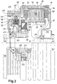
- the pressure plate 54 can move freely axially, wherein by the in the lower part of FIG. 3rd bolt 55 shown is mounted. These bolts 55 point only at their front, in the fixed Brake caliper reaching a thread during the end through the pressure plate 54 part with a smooth Provide outer diameter for better axial mobility is. Likewise, in the lower part of Fig. 3 by the brake caliper 50 reaching long screws 57 shown in axial direction throughout in the carrier 29 with a Engage the thread to attach the brake to the stator.
- a coil 59 in the Actuator 42 provided radially inside the coil springs 56 extends in the circumferential direction.
- the pressure plate 54 can in be divided into several parts, preferably into two parts each occupy approximately a semicircular section, especially when dividing part of the slats circumferentially in sectors.
- Several coil springs 56 and a division of the brake into several sector-shaped Sections can increase brake safety. So can for example, in the event of a spring break, the pressure force from the remaining coil springs are adopted.
- the mechanical Closing elements permanently apply the pressure for the brake apply and only through the release device, for example in the form of electromagnets.
- the brake is released automatically and stops the elevator.
- a contact switch is used to detect the condition of the brake 60 arranged on the brake caliper 50 by a adjusting screw 61 running in the pressure plate 54 can be triggered. In this way, either a loosening of the Brake by tightening the pressure plate 54 against the coil 59 are detected or the brake is closed by the coil springs 56 triggered system of the pressure plate 54 against the brake discs.
- a screw cap 62 lockable adjustment opening 63 the adjustment screw 61 can be adjusted or readjusted from the outside.
Landscapes
- Engineering & Computer Science (AREA)
- Power Engineering (AREA)
- Physics & Mathematics (AREA)
- Electromagnetism (AREA)
- Connection Of Motors, Electrical Generators, Mechanical Devices, And The Like (AREA)
- Cage And Drive Apparatuses For Elevators (AREA)
- Braking Arrangements (AREA)
- Permanent Magnet Type Synchronous Machine (AREA)
Abstract
Description
- Fig. 1
- einen seitlichen Teilschnitt durch eine erfindungsgemäße elektrische Maschine,
- Fig. 2
- eine Vorderansicht der elektrischen Maschine aus Fig. 1 mit einer Halterung für den Stator sowie der Seiltrommel und
- Fig. 3
- einen detaillierten seitlichen Teilschnitt der Maschine aus Fig. 1, bei der die erfindungsgemäße Anordnung und Ausbildung der Bremseinrichtung deutlich wird.
Claims (16)
- Elektrische Maschine, insbesondere für Fahrstuhlantrieb, mit einem feststehenden innenliegenden Stator und einem im wesentlichen das Maschinengehäuse bildenden rotierenden Außenläufer, der zumindest teilweise den Stator übergreift und im äußeren Bereich seiner axialen Ausdehnung gelagert ist, wobei Stator (12) und Außenläufer (13) über einen sie in radialer Richtung trennenden, in axialer Richtung verlaufenden Luftspalt (36) in elektromagnetisch induzierter Verbindung zueinander stehen, und mit einer Bremseinrichtung (40) zwischen Stator und Außenläufer, die innerhalb des Maschinengehäuses angeordnet ist.
- Elektrische Maschine nach Anspruch 1, dadurch gekennzeichnet, daß die Bremseinrichtung (40) außerhalb eines Motorteils liegt, wobei der Motorteil vorzugsweise den von dem Luftspalt (36) umgebenen zylinderförmigen Raum umfaßt.
- Elektrische Maschine nach Anspruch 1 oder 2, dadurch gekennzeichnet, daß die Bremseinrichtung (40) im Bereich bzw. radial innerhalb eines mit dem Außenläufer (13) gekoppelten Treibrades zum Antrieb eines Seils o.dgl. angeordnet ist, wobei sie bevorzugt zumindest teilweise mit dem Treibrad verbunden ist.
- Elektrische Maschine nach einem der vorhergehenden Ansprüche, dadurch gekennzeichnet, daß die Bremseinrichtung (40) Bremsflächen aufweist, die jeweils dem Stator (12) und dem Außenläufer (13) zugeordnet sind und zumindest teilweise bewegbar sind, wobei sie vorzugsweise in axialer Richtung frei bewegbar gehaltert und durch Bremsdruck in axialer Richtung der Maschine (11) gegeneinander beaufschlagbar sind.
- Elektrische Maschine nach Anspruch 4, dadurch gekennzeichnet, daß die Bremsflächen des Stators (12) und/oder des Außenläufers (13) in Umfangsrichtung verlaufend im wesentlichen mit Kreisringoberflächen ausgebildet sind, vorzugsweise auf Kreisringscheiben angeordnet sind, wobei insbesondere die Kreisringe in mehrere Kreisringsektoren unterteilt sind, die vorzugsweise jeweils unabhängig voneinander bewegbar sind.
- Elektrische Maschine nach Anspruch 5, gekennzeichnet durch eine Lamellenbremse mit mehreren Kreisringscheiben an Stator (12) und an Außenläufer (13), die abwechselnd ineinandergreifen, wobei vorzugsweise wenigstens eine Kreisringscheibe (53) an einem Ende der Lamellenbremse axial fest abstützbar ist, insbesondere an dem Stator.
- Elektrische Maschine nach einem der vorhergehenden Ansprüche, dadurch gekennzeichnet, daß eine Betätigungseinrichtung (42) für die Bremseinrichtung (40) an dem Stator (12) angeordnet ist, wobei sie vorzugsweise wenigstens eine Schließvorrichtung zum Schließen der Bremseinrichtung und wenigstens eine Lösevorrichtung zum Lösen der Bremseinrichtung aufweist, die insbesondere jeweils Schließ- und/oder Löseelemente umfassen.
- Elektrische Maschine nach Anspruch 7, dadurch gekennzeichnet, daß die Schließvorrichtung wenigstens ein elastisches mechanisches Schließelement zum Aufbringen der Andruckkraft für die Bremseinrichtung (40) aufweist, dessen Wirkungsrichtung in axialer Richtung verläuft, insbesondere durch Bremsflächen hindurch, und das vorzugsweise als Schraubenfeder (56) ausgebildet ist, wobei insbesondere die Schließvorrichtung eine permanente Andruckkraft auf die Bremseinrichtung ausübt, und vorzugsweise mehrere Schließelemente in Umfangsrichtung gleichmäßig verteilt sind.
- Elektrische Maschine nach Anspruch 7 oder 8, dadurch gekennzeichnet, daß die Lösevorrichtung wenigstens ein elektromechanisches Löseelement aufweist, vorzugsweise einen Elektromagneten, der insbesondere als im wesentlichen in Umfangsrichtung gewickelte Spule (59) ausgebildet ist, wobei vorzugsweise das wenigstens eine Löseelement in geringem Abstand zu wenigstens einem Schließelement der Schließvorrichtung angeordnet ist.
- Elektrische Maschine nach einem der Ansprüche 7 bis 9, gekennzeichnet durch zusätzliche Lösemittel zum Lösen der Bremseinrichtung (40), die vorzugsweise als mechanische Lösemittel ausgebildet sind und ein Kraftübertragungselement aufweisen, das aus der Maschine (11) herausgeführt ist zur externen Betätigung, wobei insbesondere ein Angriffspunkt für die von den zusätzlichen Lösemitteln übertragene Kraft an der Bremseinrichtung im Bereich der Löseelemente liegt.
- Elektrische Maschine nach einem der vorhergehenden Ansprüche, dadurch gekennzeichnet, daß sie wenigstens eine Spule zur zumindest teilweisen Erzeugung der elektromagnetischen Induktion in dem Luftspalt (36) aufweist, die insbesondere als Statorwicklung (30) an dem Stator (12) angeordnet ist, wobei die Maschine vorzugsweise weiters wenigstens einen Permanentmagneten (35) aufweist, der an dem Außenläufer (13) angeordnet ist und eine geringe Dicke aufweist.
- Elektrische Maschine nach Anspruch 3, dadurch gekennzeichnet, daß das Treibrad als Seiltrommel (23) mit mehreren außenliegenden, in Umfangsrichtung verlaufenden Rillen (27) zur Aufnahme des Seils sowie dessen Antrieb durch Reibschluß ausgebildet ist, wobei sie vorzugsweise axial versetzt ist zu dem Motorteil bzw. dem von dem Luftspalt (36) umgebenen Raum, insbesondere geringeren Durchmesser als der Luftspalt aufweist.
- Elektrische Maschine nach Anspruch 12, dadurch gekennzeichnet, daß die Seiltrommel (23) auf einen Abschnitt des Außenläufers (13) übergreifend aufgesetzt ist, vorzugsweise auf ein Ende des Außenläufers, wobei sie insbesondere durch den Außenläufer radial abgestützt ist.
- Elektrische Maschine nach Anspruch 12 oder 13, dadurch gekennzeichnet, daß wenigstens ein Lager (16) für den Außenläufer (13) in dem von der Seiltrommel (23) umgebenen Bereich angeordnet ist, wobei sich die Seiltrommel vorzugsweise über eine in radialer Richtung durchgängige Verbindung des Außenläufers an dem Lager derart abstützt, daß Lager und Seiltrommel etwa in einer Ebene liegen, in welcher der Außenläufer als eine die im wesentlichen ununterbrochene Stirnfläche des Gehäuses bildende Scheibe verläuft.
- Elektrische Maschine nach einem der vorhergehenden Ansprüche, dadurch gekennzeichnet, daß der Außenläufer (13) an seinen beiden Enden gelagert ist, wobei die Lager (16) vorzugsweise an den beiden Enden der Statorwelle (37) des Stators (12) angeordnet sind.
- Elektrische Maschine nach einem der vorhergehenden Ansprüche, dadurch gekennzeichnet, daß an dem Außenläufer (13), insbesondere an einem an das Treibrad angrenzenden Bereich, eine in Umfangsrichtung umlaufende Verzahnung, vorzugsweise ein Zahnkranz, verläuft, die an dem Außenläufer angeformt oder als separates Teil angebracht ist, wobei an die Verzahnung ein Notantriebsmotor mit einem insbesondere beweglichen Zahnrad ankoppelbar ist, so daß der Notantriebsmotor, eine Antriebskraft auf den Außenläufer überträgt.
Applications Claiming Priority (2)
| Application Number | Priority Date | Filing Date | Title |
|---|---|---|---|
| DE19815962 | 1998-04-09 | ||
| DE1998115962 DE19815962A1 (de) | 1998-04-09 | 1998-04-09 | Elektrische Maschine, insbesondere für Fahrstuhlantrieb |
Publications (2)
| Publication Number | Publication Date |
|---|---|
| EP0949743A2 true EP0949743A2 (de) | 1999-10-13 |
| EP0949743A3 EP0949743A3 (de) | 2000-07-19 |
Family
ID=7864128
Family Applications (1)
| Application Number | Title | Priority Date | Filing Date |
|---|---|---|---|
| EP99106572A Withdrawn EP0949743A3 (de) | 1998-04-09 | 1999-03-31 | Elektrische Maschine, insbesondere für Fahrstuhlantrieb |
Country Status (3)
| Country | Link |
|---|---|
| EP (1) | EP0949743A3 (de) |
| JP (1) | JPH11299201A (de) |
| DE (1) | DE19815962A1 (de) |
Cited By (9)
| Publication number | Priority date | Publication date | Assignee | Title |
|---|---|---|---|---|
| EP1043261A3 (de) * | 1999-04-05 | 2002-07-17 | Mitsubishi Denki Kabushiki Kaisha | Aufzugsantrieb |
| EP0970912B1 (de) * | 1998-07-07 | 2004-11-03 | Hitachi, Ltd. | Aufzug |
| WO2004099056A3 (de) * | 2003-05-05 | 2005-01-13 | Waagner Biro Germany Stage Sys | Seilwinde |
| EP1796245A1 (de) * | 2005-12-09 | 2007-06-13 | Moteurs Leroy-Somer | Elektrische Drehmaschine mit einer Bremse, die mit zwei entgegengesetzten Flächen zusammen wirkt |
| GB2485226A (en) * | 2010-11-08 | 2012-05-09 | Siemag Tecberg Gmbh | Integrated hoisting machine stator support |
| WO2015078691A3 (de) * | 2013-11-26 | 2015-09-11 | Siemens Aktiengesellschaft | Elektromaschine, insbesondere elektromotor, und verfahren zum bremsen einer elektromaschine |
| CN115417279A (zh) * | 2022-09-14 | 2022-12-02 | 浙江弗尔德驱动科技有限公司 | 一种内转子永磁同步安全节能型曳引机 |
| CN117674512A (zh) * | 2024-02-03 | 2024-03-08 | 浙江弗尔德驱动科技有限公司 | 一种新能源驱动永磁电机 |
| CN119160741A (zh) * | 2024-09-23 | 2024-12-20 | 日立电梯电机(广州)有限公司 | 曳引机 |
Families Citing this family (10)
| Publication number | Priority date | Publication date | Assignee | Title |
|---|---|---|---|---|
| JP4606619B2 (ja) * | 2001-03-07 | 2011-01-05 | 三菱電機株式会社 | エレベーター用巻上機 |
| JP2002274770A (ja) * | 2001-03-14 | 2002-09-25 | Mitsubishi Electric Corp | エレベータ用ギヤーレス巻上機 |
| WO2007069312A1 (ja) * | 2005-12-14 | 2007-06-21 | Mitsubishi Denki Kabushiki Kaisha | エレベータの電磁マグネット装置 |
| EP1988051B1 (de) * | 2006-02-22 | 2019-01-09 | Mitsubishi Denki Kabushiki Kaisha | Bremseinheit einer aufzugwindemaschine und herstellungsverfahren dafür |
| DE102006032992A1 (de) * | 2006-07-17 | 2008-01-31 | Siemens Ag | Rotor für eine elektrische Maschine sowie elektrische Maschine mit einem derartigen Rotor |
| DE102006056079A1 (de) * | 2006-11-28 | 2008-05-29 | Robert Bosch Gmbh | Aufzugsmotor |
| JP5071306B2 (ja) * | 2008-08-26 | 2012-11-14 | トヨタ自動車株式会社 | 駆動装置 |
| DE102016223968A1 (de) * | 2016-12-01 | 2018-06-07 | Volkswagen Aktiengesellschaft | Zusammengebaute Gehäuseanordnung für eine elektrische Maschine und Herstellverfahren |
| CN110436297B (zh) | 2018-05-03 | 2022-04-29 | 奥的斯电梯公司 | 制动盘释放装置、盘车装置、电梯救援套件和方法 |
| FR3110783B1 (fr) | 2020-05-19 | 2022-04-22 | Conductix Wampfler France | Dispositif d’enroulement/déroulement d’un lien |
Family Cites Families (7)
| Publication number | Priority date | Publication date | Assignee | Title |
|---|---|---|---|---|
| US2974756A (en) * | 1958-03-03 | 1961-03-14 | Reliance Electric & Eng Co | Automatic reset brake release |
| US4921078A (en) * | 1988-02-18 | 1990-05-01 | Sommer Company | Electro-shear brake |
| DE4233759A1 (de) * | 1992-10-07 | 1994-04-14 | Blocher Elektromotorenwerk Dre | Hebezeugantrieb |
| DE19500589A1 (de) * | 1995-01-11 | 1996-07-18 | Koersgen Heinz Norbert Dipl In | Elektrischer Radnabenmotor ohne Getriebe, mit außen laufendem Rotor und elektromagnetisch gelüfteter Federdruckbremse insbesondere zum Antrieb von Rollstühlen und anderen Kleinfahrzeugen |
| FI98724C (fi) * | 1995-03-24 | 1997-08-11 | Kone Oy | Hissikoneiston hätäkäyttölaite |
| DE19511077C2 (de) * | 1995-03-25 | 1997-02-06 | Thyssen Aufzuege Gmbh | Getriebelose Treibscheiben-Fördermaschine |
| FI103498B1 (fi) * | 1996-09-05 | 1999-07-15 | Kone Corp | Järjestely hissikoneiston jarrun avaamiseen |
-
1998
- 1998-04-09 DE DE1998115962 patent/DE19815962A1/de not_active Withdrawn
-
1999
- 1999-01-12 JP JP516099A patent/JPH11299201A/ja active Pending
- 1999-03-31 EP EP99106572A patent/EP0949743A3/de not_active Withdrawn
Cited By (13)
| Publication number | Priority date | Publication date | Assignee | Title |
|---|---|---|---|---|
| EP0970912B1 (de) * | 1998-07-07 | 2004-11-03 | Hitachi, Ltd. | Aufzug |
| EP1043261A3 (de) * | 1999-04-05 | 2002-07-17 | Mitsubishi Denki Kabushiki Kaisha | Aufzugsantrieb |
| WO2004099056A3 (de) * | 2003-05-05 | 2005-01-13 | Waagner Biro Germany Stage Sys | Seilwinde |
| EP1796245A1 (de) * | 2005-12-09 | 2007-06-13 | Moteurs Leroy-Somer | Elektrische Drehmaschine mit einer Bremse, die mit zwei entgegengesetzten Flächen zusammen wirkt |
| FR2894731A1 (fr) * | 2005-12-09 | 2007-06-15 | Leroy Somer Moteurs | Machine electrique tournante comportant un frein venant en prise avec au moins une surface de freinage s'etendant non entierement perpendiculairement a l'axe de rotation |
| GB2485226B (en) * | 2010-11-08 | 2016-12-21 | Siemag Tecberg Gmbh | Torque support for an integrated hoisting machine |
| GB2485226A (en) * | 2010-11-08 | 2012-05-09 | Siemag Tecberg Gmbh | Integrated hoisting machine stator support |
| WO2015078691A3 (de) * | 2013-11-26 | 2015-09-11 | Siemens Aktiengesellschaft | Elektromaschine, insbesondere elektromotor, und verfahren zum bremsen einer elektromaschine |
| CN115417279A (zh) * | 2022-09-14 | 2022-12-02 | 浙江弗尔德驱动科技有限公司 | 一种内转子永磁同步安全节能型曳引机 |
| CN115417279B (zh) * | 2022-09-14 | 2024-03-26 | 浙江弗尔德驱动科技有限公司 | 一种内转子永磁同步安全节能型曳引机 |
| CN117674512A (zh) * | 2024-02-03 | 2024-03-08 | 浙江弗尔德驱动科技有限公司 | 一种新能源驱动永磁电机 |
| CN117674512B (zh) * | 2024-02-03 | 2024-05-17 | 浙江弗尔德驱动科技有限公司 | 一种新能源驱动永磁电机 |
| CN119160741A (zh) * | 2024-09-23 | 2024-12-20 | 日立电梯电机(广州)有限公司 | 曳引机 |
Also Published As
| Publication number | Publication date |
|---|---|
| EP0949743A3 (de) | 2000-07-19 |
| DE19815962A1 (de) | 1999-10-14 |
| JPH11299201A (ja) | 1999-10-29 |
Similar Documents
| Publication | Publication Date | Title |
|---|---|---|
| EP0949743A2 (de) | Elektrische Maschine, insbesondere für Fahrstuhlantrieb | |
| EP2005020B1 (de) | Elektromagnetisch lüftende federdruckbremse in gestalt einer zweikreisigen vierkantbremse | |
| DE3801716C2 (de) | Differentialgetriebe | |
| DE69707674T2 (de) | Elektromagnetisch lösbare sicherheits-reibungsbremse | |
| DE69607100T2 (de) | Motor mit Reduktionsgetriebe, Montageverfahren und Wartungsverfahren desselben | |
| DE2747466C2 (de) | Nachstelleinrichtung zur Veränderung des maximal möglichen Abstandes zwischen Magnetgehäuse und Ankerscheibe bei einer Elektromagnet-Bremse | |
| EP3306786B1 (de) | Elektromotor | |
| EP0944781A1 (de) | Elektromechanisch betätigbare bremse | |
| DE19733169A1 (de) | Elektromagnetisch gelüftete Reibungs-Sicherheitsbremse mit zwei unabhängigen Bremskreisen | |
| DE202015101779U1 (de) | Permanentmagnet-Synchrondirektantrieb-Hebevorrichtung mit einem einstufigen Zahnrad | |
| DE60204256T2 (de) | Durch Drehmoment lösbare Scheibenbremse | |
| DE3330528C2 (de) | ||
| DE4225158A1 (de) | Elektromaschinensystem | |
| DE60205878T2 (de) | Brems-kupplung anordnung | |
| EP0729912B1 (de) | Kettenzug mit einer durch die Bremse verstellbaren Kupplung | |
| DE10305434A1 (de) | Adapter und Getriebemotor | |
| DE10310777A1 (de) | Elektromaschine mit koaxialen, mehrfach abwechselnden Magnet- und Wicklungslagen | |
| DE4217099C1 (de) | Elektrischer rotationsmotor mit retarderbremse | |
| DE1173758B (de) | Elektromotorische Verstellvorrichtung | |
| EP1576713A1 (de) | Adapter, getriebemotor und getriebemotor-baukasten | |
| DE29510168U1 (de) | Federdruck-Zweikreisbremssystem | |
| DE102021104253A1 (de) | Axialflussmaschine mit Bremsvorrichtung | |
| EP0729913B1 (de) | Kettenzug mit auf beide Seiten der Kupplung wirkender Bremse | |
| DE19905390C1 (de) | Aufzugsantrieb mit elektrischem Antriebsmotor | |
| DE102009028151A1 (de) | Stellantrieb |
Legal Events
| Date | Code | Title | Description |
|---|---|---|---|
| PUAI | Public reference made under article 153(3) epc to a published international application that has entered the european phase |
Free format text: ORIGINAL CODE: 0009012 |
|
| AK | Designated contracting states |
Kind code of ref document: A2 Designated state(s): AT BE CH DE ES FR GB IT LI NL |
|
| AX | Request for extension of the european patent |
Free format text: AL;LT;LV;MK;RO;SI |
|
| PUAL | Search report despatched |
Free format text: ORIGINAL CODE: 0009013 |
|
| AK | Designated contracting states |
Kind code of ref document: A3 Designated state(s): AT BE CH CY DE DK ES FI FR GB GR IE IT LI LU MC NL PT SE |
|
| AX | Request for extension of the european patent |
Free format text: AL;LT;LV;MK;RO;SI |
|
| RIC1 | Information provided on ipc code assigned before grant |
Free format text: 7H 02K 7/10 A, 7H 02K 7/102 B, 7B 66B 11/04 B, 7B 66B 5/02 B |
|
| 17P | Request for examination filed |
Effective date: 20010118 |
|
| AKX | Designation fees paid |
Free format text: AT BE CH CY DE DK ES FI FR LI |
|
| RBV | Designated contracting states (corrected) |
Designated state(s): AT BE CH DE ES FR GB IT LI NL |
|
| STAA | Information on the status of an ep patent application or granted ep patent |
Free format text: STATUS: THE APPLICATION IS DEEMED TO BE WITHDRAWN |
|
| 18D | Application deemed to be withdrawn |
Effective date: 20051001 |