EP0949638B1 - Isolator für elektrische Übertragungs- und Verteilungsleitungen, mit verbessertem Wiederstand gehen Biegespannungen - Google Patents
Isolator für elektrische Übertragungs- und Verteilungsleitungen, mit verbessertem Wiederstand gehen Biegespannungen Download PDFInfo
- Publication number
- EP0949638B1 EP0949638B1 EP99201049A EP99201049A EP0949638B1 EP 0949638 B1 EP0949638 B1 EP 0949638B1 EP 99201049 A EP99201049 A EP 99201049A EP 99201049 A EP99201049 A EP 99201049A EP 0949638 B1 EP0949638 B1 EP 0949638B1
- Authority
- EP
- European Patent Office
- Prior art keywords
- tube
- flange
- insulator
- pins
- flexural
- Prior art date
- Legal status (The legal status is an assumption and is not a legal conclusion. Google has not performed a legal analysis and makes no representation as to the accuracy of the status listed.)
- Expired - Lifetime
Links
Images
Classifications
-
- H—ELECTRICITY
- H01—ELECTRIC ELEMENTS
- H01B—CABLES; CONDUCTORS; INSULATORS; SELECTION OF MATERIALS FOR THEIR CONDUCTIVE, INSULATING OR DIELECTRIC PROPERTIES
- H01B17/00—Insulators or insulating bodies characterised by their form
- H01B17/38—Fittings, e.g. caps; Fastenings therefor
- H01B17/40—Cementless fittings
Definitions
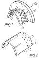
- hollow insulators are generally constituted by a tube made of composite material, typically fiberglass-reinforced plastic, around which insulating ribs made of silicone material are arranged; suitable metallic flanges are also fixed to one or both ends of the tube and allow to couple the insulator to an additional element, such as for example another insulator or the frame of a supporting pylon.
- the aim of the present invention is to provide a hollow insulator, particularly for pole heads of supporting pylons in electric transmission and/or distribution lines, which allows to considerably improve the maximum flexural moment that can be withstood with respect to that of conventional-type insulators.
- Another object of the present invention is to provide a hollow insulator, particularly for pole heads of supporting pylons in electric transmission and/or distribution lines, which allows to achieve a considerable improvement in the level of flexural moment that can be withstood without changing the types of material used, the geometric dimensions and the production processes of said insulator.
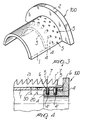
- a hollow insulator for electric transmission and/or distribution lines comprising an insulating tube made of composite material which is coupled, at least at an end portion thereof, to a metal flange by means of a plurality of connection means adapted to transfer to the flange flexural stresses due to flexural moments applied to the tube, said connection means working substantially under shearing stress and comprising pins which are fixed to the flange and engage in corresponding holes formed in the tube, characterized in that said pins and said holes are arranged along at least two parallel circumferential rows and have an axis which is substantially perpendicular to the longitudinal axis of the insulating tube, the pins and the corresponding holes formed in the insulating tube and belonging to two adjacent parallel circumferential rows being mutually staggered with respect to the longitudinal axis of said tube.
- connection means are constituted by metallic or composite pins 4 which are fixed to the flange 100 and engage in corresponding holes 5 formed in the surface of the tube 1; in particular, in the illustrated embodiment the pins 4 are constituted by steel cylinders, at least one end portion 4' whereof is threaded, which are screwed in blind seats 6 formed in the flange 100.
- the pins 4, which protrude from the cylindrical part 3 of the flange, are arranged on such part 3 along one or more circumferential rows and the axis 7 of each pin 4 is substantially perpendicular to the longitudinal axis 8 of the tube 1.
- the insulator according to the present invention allows to fully achieve the intended aim and objects, since it allows to considerably increase the maximum flexural moment that can be withstood with respect to conventional-type insulators; moreover, experimental tests and numerical analysis have shown that the insulator has a fracture mode which is not brittle but plastic, since between the flexural moment at the elastic limit (first ply failure) and the flexural moment that produces fracture (ultimate laminate failure) there is a significant margin over which the insulating tube retains the loads applied, undergoing great permanent deformations (delamination) but maintaining its structural integrity and thus increasing safety.
Landscapes
- Insulators (AREA)
- Inorganic Insulating Materials (AREA)
- Organic Insulating Materials (AREA)
- Waveguides (AREA)
- Insulating Bodies (AREA)
Claims (4)
- Hohler Isolator fiir elektrische Übertragungs- und/oder Verteilungsleitungen, der eine Isolationsröhre (1) aufweist, die aus Verbundmaterial hergestellt ist, welche an wenigstens einem Endteil davon mit einem Metallflansch (100) mittels einer Vielzahl von Verbindungsmitteln verbunden ist, die daran angepasst sind, auf den Flansch (100) Biegebeanspruchungen aufgrund von Biegemomenten zu übertragen, die auf die Röhre (1) ausgeübt werden, wobei die Verbindungsmittel daran angepasst sind, im Wesentlichen unter Scherspannungen zu arbeiten und aus Stiften (4) bestehen, die am Flansch (100) befestigt sind, und die in entsprechende Löcher (5) eingreifen, die in der Röhre (1) ausgebildet werden, dadurch gekennzeichnet, dass die Stifte (4) und die Löcher (5) entlang wenigstens zwei parallelen Umfangsreihen angeordnet sind und eine Achse (7) aufweisen, welche im Wesentlichen senkrecht auf die longitudinale Achse (8) der Isolationsröhre (1) ist, wobei die Stifte (4) und die zugeordneten Löcher (5), die in der Isolationsröhre (1) gebildet werden und die jeweils zu zwei benachbarten parallelen Umfangsreihen gehören, beiderseitig in Bezug auf die longitudinale Achse (8) der Röhre (1) gestaffelt sind.
- Hohler Isolator nach Anspruch 1, dadurch gekennzeichnet, dass die Stifte (4) aus Stahlzylindern bestehen, die wenigstens an einem Endteil (4') in Sitze (6) geschraubt werden, die im Flansch (100) vorgegeben sind.
- Hohler Isolator nach einem oder mehreren der vorangehenden Ansprüchen, dadurch gekennzeichnet, dass die Stifte (4) so hoch sind oder niedriger als der Abstand (30), der zwischen einem Boden der Sitze (6), die im Flansch (1) vorgegeben werden, und einer äußeren Oberfläche der Isolatorrölire (1) berechnet ist.
- Hohler Isolator nach Anspruch 1, dadurch gekennzeichnet, dass der Metallflansch (100) aus Aluminium hergestellt ist und mit der inneren Oberfläche der Röhre (1) verbunden ist.
Applications Claiming Priority (2)
| Application Number | Priority Date | Filing Date | Title |
|---|---|---|---|
| ITMI980751 | 1998-04-08 | ||
| IT98MI000751A IT1299049B1 (it) | 1998-04-08 | 1998-04-08 | Isolatore particolarmente per linee elettriche di trasmissione e distribuzione, avente caratteristiche migliorate di resistenza alle |
Publications (3)
| Publication Number | Publication Date |
|---|---|
| EP0949638A2 EP0949638A2 (de) | 1999-10-13 |
| EP0949638A3 EP0949638A3 (de) | 2000-11-15 |
| EP0949638B1 true EP0949638B1 (de) | 2005-07-20 |
Family
ID=11379707
Family Applications (1)
| Application Number | Title | Priority Date | Filing Date |
|---|---|---|---|
| EP99201049A Expired - Lifetime EP0949638B1 (de) | 1998-04-08 | 1999-04-08 | Isolator für elektrische Übertragungs- und Verteilungsleitungen, mit verbessertem Wiederstand gehen Biegespannungen |
Country Status (8)
| Country | Link |
|---|---|
| US (1) | US6218626B1 (de) |
| EP (1) | EP0949638B1 (de) |
| AT (1) | ATE300090T1 (de) |
| BR (1) | BR9901050A (de) |
| DE (1) | DE69926167T2 (de) |
| IT (1) | IT1299049B1 (de) |
| PL (1) | PL332441A1 (de) |
| ZA (1) | ZA992573B (de) |
Families Citing this family (5)
| Publication number | Priority date | Publication date | Assignee | Title |
|---|---|---|---|---|
| JP4376174B2 (ja) * | 2004-12-01 | 2009-12-02 | 日本碍子株式会社 | ポリマーsp碍子 |
| CN102347122B (zh) * | 2010-07-23 | 2013-08-28 | 江苏神马电力股份有限公司 | 一种绝缘管缠绕挂纱系统 |
| CN103177829A (zh) * | 2011-12-20 | 2013-06-26 | 江苏神马电力股份有限公司 | 一种空心复合绝缘子的法兰 |
| CN105914674B (zh) * | 2016-06-07 | 2018-04-03 | 浙江华蕴海洋工程技术服务有限公司 | 一种电缆保护管 |
| CN113742889B (zh) * | 2021-07-29 | 2024-04-02 | 中国南方电网有限责任公司超高压输电公司检修试验中心 | 绝缘子的选型方法 |
Family Cites Families (7)
| Publication number | Priority date | Publication date | Assignee | Title |
|---|---|---|---|---|
| US1728531A (en) * | 1926-07-28 | 1929-09-17 | Westinghouse Electric & Mfg Co | High-voltage insulator |
| US3213254A (en) * | 1962-12-31 | 1965-10-19 | Westinghouse Electric Corp | Arc resistant orifice embodying fluorocarbon resins and a plastic member |
| JPH07245027A (ja) | 1994-03-08 | 1995-09-19 | Hitachi Kasei Mold Kk | 絶縁支柱 |
| DE4421343A1 (de) * | 1994-06-17 | 1995-12-21 | Hoechst Ceram Tec Ag | Hochspannungsisolator aus Keramik |
| DE19503324A1 (de) * | 1995-02-02 | 1996-08-08 | Hoechst Ceram Tec Ag | Isolator mit Kittverbindung und Verfahren zu seiner Herstellung |
| US5981878A (en) * | 1996-04-22 | 1999-11-09 | Hubbell Incorporated | Polymer insulators with metal caps |
| EP0933787A3 (de) | 1998-02-03 | 2000-11-02 | Cellpack AG | Säulenförmiger elektrischer Isolator |
-
1998
- 1998-04-08 IT IT98MI000751A patent/IT1299049B1/it active IP Right Grant
-
1999
- 1999-04-05 US US09/285,756 patent/US6218626B1/en not_active Expired - Fee Related
- 1999-04-07 BR BR9901050-0A patent/BR9901050A/pt not_active Application Discontinuation
- 1999-04-07 ZA ZA9902573A patent/ZA992573B/xx unknown
- 1999-04-08 PL PL99332441A patent/PL332441A1/xx unknown
- 1999-04-08 DE DE69926167T patent/DE69926167T2/de not_active Expired - Fee Related
- 1999-04-08 EP EP99201049A patent/EP0949638B1/de not_active Expired - Lifetime
- 1999-04-08 AT AT99201049T patent/ATE300090T1/de not_active IP Right Cessation
Also Published As
| Publication number | Publication date |
|---|---|
| US6218626B1 (en) | 2001-04-17 |
| EP0949638A2 (de) | 1999-10-13 |
| DE69926167D1 (de) | 2005-08-25 |
| ITMI980751A1 (it) | 1999-10-08 |
| PL332441A1 (en) | 1999-10-11 |
| EP0949638A3 (de) | 2000-11-15 |
| ATE300090T1 (de) | 2005-08-15 |
| IT1299049B1 (it) | 2000-02-07 |
| BR9901050A (pt) | 2000-01-18 |
| DE69926167T2 (de) | 2006-04-27 |
| ZA992573B (en) | 1999-10-07 |
Similar Documents
| Publication | Publication Date | Title |
|---|---|---|
| US5563379A (en) | Composite electrical insulator | |
| US7180003B2 (en) | Composite insulator | |
| US5291366A (en) | Surge voltage arrester | |
| KR100375646B1 (ko) | 고압인가를위한실리콘고무로제조된전기절연체 | |
| EP3813083B1 (de) | Isolator mit flansch und isoliersäule | |
| EP0949638B1 (de) | Isolator für elektrische Übertragungs- und Verteilungsleitungen, mit verbessertem Wiederstand gehen Biegespannungen | |
| US4057687A (en) | Connection between core and armatures of structures comprising a core of agglomerated fibres | |
| US3504100A (en) | Pressure connections between overlapping bus bar ends | |
| US5986216A (en) | Reinforced insulator | |
| US8420971B2 (en) | Switching chamber insulation arrangement for a circuit breaker | |
| EP3129991B1 (de) | Leiter für blanke stromfreileitungen, insbesondere für mittelhohe wärmegrenze, und geringe ausdehnung bei hohen elektronische lasten | |
| CA2104066A1 (en) | Reduced mechanical stress bushing and conductor rod assembly | |
| US20230378737A1 (en) | Insulating cross arm and preparation method thereof, and transmission pole | |
| US12603487B2 (en) | Bushing and manufacturing method therefor | |
| CN111883302B (zh) | 一种具有中间加强筋的电缆结构 | |
| US5753864A (en) | Supporting insulator | |
| CA2137659C (en) | Composite insulator | |
| US2191171A (en) | Insulator | |
| US6156979A (en) | Bushing device and bushing assembly including it | |
| KR20140006533A (ko) | 초고압 전력케이블 절연접속함의 절연통 체결 구조 | |
| US6118078A (en) | Structural element | |
| US5916397A (en) | Method of manufacturing an insulator made of a composite material | |
| CN222620587U (zh) | 一种高强度复合套管 | |
| EP0948000B1 (de) | Isolator mit Schirmen | |
| CN216045922U (zh) | 一种耐候效果好高效防磨损的橡胶软管 |
Legal Events
| Date | Code | Title | Description |
|---|---|---|---|
| PUAI | Public reference made under article 153(3) epc to a published international application that has entered the european phase |
Free format text: ORIGINAL CODE: 0009012 |
|
| AK | Designated contracting states |
Kind code of ref document: A2 Designated state(s): AT BE CH DE DK ES FI FR IT LI NL SE |
|
| AX | Request for extension of the european patent |
Free format text: AL;LT;LV;MK;RO;SI |
|
| PUAL | Search report despatched |
Free format text: ORIGINAL CODE: 0009013 |
|
| AK | Designated contracting states |
Kind code of ref document: A3 Designated state(s): AT BE CH CY DE DK ES FI FR GB GR IE IT LI LU MC NL PT SE |
|
| AX | Request for extension of the european patent |
Free format text: AL;LT;LV;MK;RO;SI |
|
| 17P | Request for examination filed |
Effective date: 20010507 |
|
| AKX | Designation fees paid |
Free format text: AT BE CH DE DK ES FI FR IT LI NL SE |
|
| 17Q | First examination report despatched |
Effective date: 20040322 |
|
| GRAP | Despatch of communication of intention to grant a patent |
Free format text: ORIGINAL CODE: EPIDOSNIGR1 |
|
| GRAS | Grant fee paid |
Free format text: ORIGINAL CODE: EPIDOSNIGR3 |
|
| GRAA | (expected) grant |
Free format text: ORIGINAL CODE: 0009210 |
|
| AK | Designated contracting states |
Kind code of ref document: B1 Designated state(s): AT BE CH DE DK ES FI FR IT LI NL SE |
|
| PG25 | Lapsed in a contracting state [announced via postgrant information from national office to epo] |
Ref country code: NL Free format text: LAPSE BECAUSE OF FAILURE TO SUBMIT A TRANSLATION OF THE DESCRIPTION OR TO PAY THE FEE WITHIN THE PRESCRIBED TIME-LIMIT Effective date: 20050720 Ref country code: FI Free format text: LAPSE BECAUSE OF FAILURE TO SUBMIT A TRANSLATION OF THE DESCRIPTION OR TO PAY THE FEE WITHIN THE PRESCRIBED TIME-LIMIT Effective date: 20050720 Ref country code: BE Free format text: LAPSE BECAUSE OF FAILURE TO SUBMIT A TRANSLATION OF THE DESCRIPTION OR TO PAY THE FEE WITHIN THE PRESCRIBED TIME-LIMIT Effective date: 20050720 Ref country code: AT Free format text: LAPSE BECAUSE OF FAILURE TO SUBMIT A TRANSLATION OF THE DESCRIPTION OR TO PAY THE FEE WITHIN THE PRESCRIBED TIME-LIMIT Effective date: 20050720 |
|
| REG | Reference to a national code |
Ref country code: CH Ref legal event code: EP |
|
| REG | Reference to a national code |
Ref country code: CH Ref legal event code: NV Representative=s name: ISLER & PEDRAZZINI AG |
|
| REF | Corresponds to: |
Ref document number: 69926167 Country of ref document: DE Date of ref document: 20050825 Kind code of ref document: P |
|
| PG25 | Lapsed in a contracting state [announced via postgrant information from national office to epo] |
Ref country code: SE Free format text: LAPSE BECAUSE OF FAILURE TO SUBMIT A TRANSLATION OF THE DESCRIPTION OR TO PAY THE FEE WITHIN THE PRESCRIBED TIME-LIMIT Effective date: 20051020 Ref country code: DK Free format text: LAPSE BECAUSE OF FAILURE TO SUBMIT A TRANSLATION OF THE DESCRIPTION OR TO PAY THE FEE WITHIN THE PRESCRIBED TIME-LIMIT Effective date: 20051020 |
|
| PG25 | Lapsed in a contracting state [announced via postgrant information from national office to epo] |
Ref country code: ES Free format text: LAPSE BECAUSE OF FAILURE TO SUBMIT A TRANSLATION OF THE DESCRIPTION OR TO PAY THE FEE WITHIN THE PRESCRIBED TIME-LIMIT Effective date: 20051031 |
|
| NLV1 | Nl: lapsed or annulled due to failure to fulfill the requirements of art. 29p and 29m of the patents act | ||
| ET | Fr: translation filed | ||
| PLBE | No opposition filed within time limit |
Free format text: ORIGINAL CODE: 0009261 |
|
| STAA | Information on the status of an ep patent application or granted ep patent |
Free format text: STATUS: NO OPPOSITION FILED WITHIN TIME LIMIT |
|
| 26N | No opposition filed |
Effective date: 20060421 |
|
| REG | Reference to a national code |
Ref country code: CH Ref legal event code: PCAR Free format text: ISLER & PEDRAZZINI AG;POSTFACH 1772;8027 ZUERICH (CH) |
|
| PGFP | Annual fee paid to national office [announced via postgrant information from national office to epo] |
Ref country code: IT Payment date: 20090427 Year of fee payment: 11 Ref country code: FR Payment date: 20090414 Year of fee payment: 11 Ref country code: DE Payment date: 20090422 Year of fee payment: 11 |
|
| PGFP | Annual fee paid to national office [announced via postgrant information from national office to epo] |
Ref country code: CH Payment date: 20090417 Year of fee payment: 11 |
|
| REG | Reference to a national code |
Ref country code: CH Ref legal event code: PL |
|
| REG | Reference to a national code |
Ref country code: FR Ref legal event code: ST Effective date: 20101230 |
|
| PG25 | Lapsed in a contracting state [announced via postgrant information from national office to epo] |
Ref country code: LI Free format text: LAPSE BECAUSE OF NON-PAYMENT OF DUE FEES Effective date: 20100430 Ref country code: DE Free format text: LAPSE BECAUSE OF NON-PAYMENT OF DUE FEES Effective date: 20101103 Ref country code: CH Free format text: LAPSE BECAUSE OF NON-PAYMENT OF DUE FEES Effective date: 20100430 |
|
| PG25 | Lapsed in a contracting state [announced via postgrant information from national office to epo] |
Ref country code: IT Free format text: LAPSE BECAUSE OF NON-PAYMENT OF DUE FEES Effective date: 20100408 |
|
| PG25 | Lapsed in a contracting state [announced via postgrant information from national office to epo] |
Ref country code: FR Free format text: LAPSE BECAUSE OF NON-PAYMENT OF DUE FEES Effective date: 20100430 |