EP0949447A1 - Self-contained electronic system for monitoring purgers, valves and installations in real time - Google Patents
Self-contained electronic system for monitoring purgers, valves and installations in real time Download PDFInfo
- Publication number
- EP0949447A1 EP0949447A1 EP97931823A EP97931823A EP0949447A1 EP 0949447 A1 EP0949447 A1 EP 0949447A1 EP 97931823 A EP97931823 A EP 97931823A EP 97931823 A EP97931823 A EP 97931823A EP 0949447 A1 EP0949447 A1 EP 0949447A1
- Authority
- EP
- European Patent Office
- Prior art keywords
- analyzer
- electronic
- elements
- self
- monitoring
- Prior art date
- Legal status (The legal status is an assumption and is not a legal conclusion. Google has not performed a legal analysis and makes no representation as to the accuracy of the status listed.)
- Granted
Links
- 238000012544 monitoring process Methods 0.000 title claims abstract description 14
- 238000009434 installation Methods 0.000 title abstract description 20
- 239000012530 fluid Substances 0.000 claims abstract description 12
- 230000003287 optical effect Effects 0.000 claims abstract description 11
- 239000000523 sample Substances 0.000 claims abstract description 6
- 239000000463 material Substances 0.000 claims description 8
- 238000004458 analytical method Methods 0.000 claims description 7
- 238000004326 stimulated echo acquisition mode for imaging Methods 0.000 claims 7
- 238000007689 inspection Methods 0.000 abstract description 3
- 238000000034 method Methods 0.000 abstract description 3
- 238000002604 ultrasonography Methods 0.000 abstract 2
- 238000011065 in-situ storage Methods 0.000 abstract 1
- 238000001514 detection method Methods 0.000 description 5
- 238000012423 maintenance Methods 0.000 description 3
- 238000005516 engineering process Methods 0.000 description 2
- 238000011144 upstream manufacturing Methods 0.000 description 2
- 230000004397 blinking Effects 0.000 description 1
- 239000000919 ceramic Substances 0.000 description 1
- 230000000295 complement effect Effects 0.000 description 1
- 230000006378 damage Effects 0.000 description 1
- 230000000694 effects Effects 0.000 description 1
- 238000005265 energy consumption Methods 0.000 description 1
- 238000004519 manufacturing process Methods 0.000 description 1
- 239000002184 metal Substances 0.000 description 1
- 238000010926 purge Methods 0.000 description 1
- 238000011084 recovery Methods 0.000 description 1
- 230000000007 visual effect Effects 0.000 description 1
- 238000010792 warming Methods 0.000 description 1
Images

Classifications
-
- F—MECHANICAL ENGINEERING; LIGHTING; HEATING; WEAPONS; BLASTING
- F16—ENGINEERING ELEMENTS AND UNITS; GENERAL MEASURES FOR PRODUCING AND MAINTAINING EFFECTIVE FUNCTIONING OF MACHINES OR INSTALLATIONS; THERMAL INSULATION IN GENERAL
- F16T—STEAM TRAPS OR LIKE APPARATUS FOR DRAINING-OFF LIQUIDS FROM ENCLOSURES PREDOMINANTLY CONTAINING GASES OR VAPOURS
- F16T1/00—Steam traps or like apparatus for draining-off liquids from enclosures predominantly containing gases or vapours, e.g. gas lines, steam lines, containers
- F16T1/38—Component parts; Accessories
- F16T1/48—Monitoring arrangements for inspecting, e.g. flow of steam and steam condensate
Definitions
- the present specification refers to a patent of Invention corresponding to a new prototype of a self sufficient electronic system for the monitoring of steam traps, valves and installations, which can be applied to the remote control of fluids in all types of installations and specially to control the operation of all kinds of steam traps and to the instant detection of steam leaks in said elements.
- Another way to control steam leaks and steam trap operation consists of the installation of fixed passive elements such as peephole o conductivity check type detecting devices. These devices are installed on line just upstream the steam trap and detect the steam flow through steam traps. These elements require the help of expensive external devices for detection and analysis fed by auxiliary power sources, which, also, require expensive installation, and mainly require human help for their correct operation. These types of elements placed upstream the steam traps require maintenance and their failure would require stopping the system for checking and repair.
- the new prototype of a self sufficient electronic system for monitoring steam traps, valves and installation can be applied to any type of valve or fluid installation or to any type of steam trap and will solve satisfactorily all problems and inconveniences present in the systems described in the present technological state due to the fact that the system of present invention is a self-sufficient system, with no need for auxiliary power, which will not be mounted in line with steam trap, but on top of said steam trap as an independent fitting, so the system can be removed without having to stop or alter said steam trap working condition.
- the system effects a continuous control on steam traps and remains fully operative without any energy consumption and in a warming state, to detect any steam leak through a steam trap and send an immediate warning.
- the new prototype, object of this invention provides one or several of the following types of information: optical, acoustic or numeric coded.
- the optical information consists of an indicator, which can show several conditions (off, blinking, on, and ordinal) depending on fluid condition through steam traps or the installation.
- the acoustic information identifies the same parameters as the optical information by means of an audible tone system.
- the numeric coded information contains the same information as previously mentioned, and in addition a code identifying the steam trap or the spot where and when the failure has taken place, in turn being sent to an optional receiver control panel for its further analysis and process.
- the new prototype, object of this invention is of a great economical importance for four essential reasons:
- the new prototype object of this invention comprises three basic elements: a triple sensor, an electronic analyzer and an optional receiver.
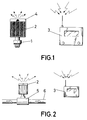
- Figure 2 shows a prototype of the new self sufficient electronic system for monitoring steam traps, valves and installations, which can be applied on any installation part or fitting.
- the multiple sensor consists of a thermocouple that detects fluid temperature, an electrode for measuring fluid conductivity and a probe to detect fluid pressure.
- the multiple sensor detects ultrasonic sounds produced in the valve or in the installation without the flow being in contact with the sensor.
- the multiple sensor is housed in a metal screwed body which is connected to the pipe or to the monitored valve or steam trap body.
- the multiple sensor is air tight so that once it is mounted it will not affect to normal operation of the installation, valve or steam trap.
- Said multiple sensor is electrically and thermally insulated by means of an element made of ceramic or similar material to prevent heat being transmitted to the electronic analyzer.
- the electronic analyzer is to be screwed on top of the multiple sensor and consists of:
- the whole analyzer is protected from the exterior with a transparent cover.
- the analyzer when not mounted, can be deactivated when required without internal manipulation. Once the system is activated the same is placed on a warning condition and generates the information of at least one, or all the types of information already described which correspond to the different possible conditions of flow parameters.
- the electronic analyzer works with an almost negligible current to guarantee the safety in the installation.
- the receiver remotely detects the coded numeric signals emitted by the analyzer and gathers and processes said information in accordance with user's needs.
- the new prototype, object of this invention can also work with total success without the help of the receiver. Indeed, in this case the identification of the leading steam trap is carried out by one or more of three types of information already indicated; visual, acoustic and numeric. Even in this case no means of additional detection or auxiliary equipment are required for an immediate spotting of steam leaks.
- FIGS. 3 and 4 represent two examples for the application of two different types of steam traps, which can be extended to any other type of steam trap, valve or element of installation. In both cases, for further simplicity, a graphic representation is shown without the optional remote receiver.
- Figure 3 shows a sample of the new prototype, object of this invention, mounted on the cover of a bimetallic thermostatic steam trap.
- Figure 4 shows a sample of the same system mounted on a monobloc steam trap body.
- the assembly becomes the smallest and most powerful and reliable steam trap system and energy control system available within the field of steam trap technology in the state of art.
Landscapes
- Engineering & Computer Science (AREA)
- General Engineering & Computer Science (AREA)
- Mechanical Engineering (AREA)
- Examining Or Testing Airtightness (AREA)
- Investigating Or Analyzing Materials By The Use Of Ultrasonic Waves (AREA)
- Testing Or Calibration Of Command Recording Devices (AREA)
- Arrangements For Transmission Of Measured Signals (AREA)
- Investigating Or Analyzing Materials By The Use Of Electric Means (AREA)
- Testing And Monitoring For Control Systems (AREA)
Abstract
Description
- The present specification refers to a patent of Invention corresponding to a new prototype of a self sufficient electronic system for the monitoring of steam traps, valves and installations, which can be applied to the remote control of fluids in all types of installations and specially to control the operation of all kinds of steam traps and to the instant detection of steam leaks in said elements.
- Current technology dealing with the control of steam trap operation and with the detection of steam leakage through said steam traps is carried out by means of portable ultrasonic and pirometric detecting devices, which require the help of experts who must inspect and check one by one all the steam traps in the installation. This task is usually carried out every six months and it is very expensive, as it requires several months in the case of large installations like oil refineries, where several thousand steam traps are in service. An inspection of this type must be done on time and every six months, whereas a great amount of energy is lost through the steam traps when their failure occurs between two consecutive inspections.
- Another way to control steam leaks and steam trap operation consists of the installation of fixed passive elements such as peephole o conductivity check type detecting devices. These devices are installed on line just upstream the steam trap and detect the steam flow through steam traps. These elements require the help of expensive external devices for detection and analysis fed by auxiliary power sources, which, also, require expensive installation, and mainly require human help for their correct operation. These types of elements placed upstream the steam traps require maintenance and their failure would require stopping the system for checking and repair.
- The new prototype of a self sufficient electronic system for monitoring steam traps, valves and installation can be applied to any type of valve or fluid installation or to any type of steam trap and will solve satisfactorily all problems and inconveniences present in the systems described in the present technological state due to the fact that the system of present invention is a self-sufficient system, with no need for auxiliary power, which will not be mounted in line with steam trap, but on top of said steam trap as an independent fitting, so the system can be removed without having to stop or alter said steam trap working condition. The system effects a continuous control on steam traps and remains fully operative without any energy consumption and in a warming state, to detect any steam leak through a steam trap and send an immediate warning.
- The new prototype, object of this invention provides one or several of the following types of information: optical, acoustic or numeric coded. The optical information consists of an indicator, which can show several conditions (off, blinking, on, and ordinal) depending on fluid condition through steam traps or the installation. The acoustic information identifies the same parameters as the optical information by means of an audible tone system. The numeric coded information contains the same information as previously mentioned, and in addition a code identifying the steam trap or the spot where and when the failure has taken place, in turn being sent to an optional receiver control panel for its further analysis and process.
- The new prototype, object of this invention, is of a great economical importance for four essential reasons:
- a) Great energy savings due to the instant spotting and identification of steam losses.
- b) Reduction of maintenance costs in steam traps due to an immediate detection of the failure in these elements, avoiding total interior destruction that can take place because of a continuous steam flow through them.
- c) It avoids the pressurization of the return condensate collectors, created by steam leakage through steam traps. This pressurization affects very unfavorably to energy saving in the whole installation and makes it difficult, and sometimes impossible, the recovery of condensate residual energy.
- d) Steam traps and valves are widely used in all types of industries, and therefore this new invention will be of wide application to industrial processes.
-
- The new prototype object of this invention comprises three basic elements: a triple sensor, an electronic analyzer and an optional receiver. Figure 2 shows a prototype of the new self sufficient electronic system for monitoring steam traps, valves and installations, which can be applied on any installation part or fitting.
- The multiple sensor consists of a thermocouple that detects fluid temperature, an electrode for measuring fluid conductivity and a probe to detect fluid pressure.
- In addition, the multiple sensor detects ultrasonic sounds produced in the valve or in the installation without the flow being in contact with the sensor.
- The multiple sensor is housed in a metal screwed body which is connected to the pipe or to the monitored valve or steam trap body. The multiple sensor is air tight so that once it is mounted it will not affect to normal operation of the installation, valve or steam trap. Said multiple sensor is electrically and thermally insulated by means of an element made of ceramic or similar material to prevent heat being transmitted to the electronic analyzer.
- The electronic analyzer is to be screwed on top of the multiple sensor and consists of:
- a) a battery system recharged by photovoltaic cells
- b) analysis and control electronic circuits
- c) optical and/or acoustic and/or numeric information systems.
-
- The whole analyzer is protected from the exterior with a transparent cover. The analyzer, when not mounted, can be deactivated when required without internal manipulation. Once the system is activated the same is placed on a warning condition and generates the information of at least one, or all the types of information already described which correspond to the different possible conditions of flow parameters. The electronic analyzer works with an almost negligible current to guarantee the safety in the installation.
- The receiver remotely detects the coded numeric signals emitted by the analyzer and gathers and processes said information in accordance with user's needs.
- The new prototype, object of this invention, can also work with total success without the help of the receiver. Indeed, in this case the identification of the leading steam trap is carried out by one or more of three types of information already indicated; visual, acoustic and numeric. Even in this case no means of additional detection or auxiliary equipment are required for an immediate spotting of steam leaks.
- The new prototype, object of this invention has a special interest for the monitoring and continuous surveillance of steam leaks in any type of steam traps. Figures 3 and 4 represent two examples for the application of two different types of steam traps, which can be extended to any other type of steam trap, valve or element of installation. In both cases, for further simplicity, a graphic representation is shown without the optional remote receiver.
- Figure 3 shows a sample of the new prototype, object of this invention, mounted on the cover of a bimetallic thermostatic steam trap.
- Figure 4 shows a sample of the same system mounted on a monobloc steam trap body. The assembly becomes the smallest and most powerful and reliable steam trap system and energy control system available within the field of steam trap technology in the state of art.
- The application of the new prototype, object of this invention, to thermostatic steam traps with external adjustment during operation provides an ideal purging system in which the complementary action of both elements result in a very effective operation without the risk of energy loss and with a reduced maintenance and a very low cost for spares.
Claims (7)
- SELF-SUFFICIENT ELECTRONIC SYSTEM FOR INSTANT MONITORING OF STEAM TRAPS, VALVES AND INSTALLATIONS, which is characterized by the following elements: a triple temperature, pressure and conductivity sensor, which can be connected to any pipe element, valve or steam trap; an electronic analyzer powered by means of rechargeable batteries and photovoltaic cells; electronic circuits for warning and control of pressure, temperature and conductivity in real time; one or various elements for optical, acoustic and numeric information corresponding to flow parameters; and an optional receiver for remote collection, analysis and treatment of the information provided by the analyzer, and all said elements could be made of differente sizes, shapes and materials with no limitations in that respect.
- A SELF-SUFFICIENT ELECTRONIC ANALYZER FOR INSTANT MONITORING OF STEAM TRAPS, VALVES AND INSTALLATIONS WITHOUT AUXILIARY POWER SOURCE, in accordance with claim 1 as previously described, characterized in that it is connected to a external probe and comprising following elements: a case externally covered by photovoltaic cells with weather protection; an electronic circuit for warning and control of one or several types of optical, acoustic and numeric coded information corresponding to flow pressure, temperature and conductivity or a combination thereof, in correspondance with fluid pressure, temperature and conductivity; and a emitter of one or several types of optical, acoustic and numeric information in correspondence with analyzer working conditions, and all said elements could be made of differente sizes, shapes and materials with no limitations in that respect.
- A STEAM TRAP WITH SELF SUFFICIENT ELECTRONIC MONITORING SYSTEM WITH REAL TIME ANALYZER, in accordance with claims 2 and 3, previously described, the steam trap being of any type, shape, size or model and all elements having no limitations with respect to geometrical shape, size or material.
- AN IMPROVED SELF-SUFFICIENT ELECTRONIC SYSTEM FOR INSTANT MONITORING OF STEAM TRAPS, VALVES AND INSTALLATIONS, in accordance with claim 1 and 2 as previously described, of the type of a sensor, electronic analyzer self-fed by batteries charged by means of photovoltaic cells, electronic circuits for an immediate warning and control of pressure, temperature and conductivity; one or more elements of optical, acoustic and numeric information corresponding to fluid parameters; and a remote optional wireless receiver, for the collection, analysis and treatment of ultrasonic information supplied by the electronic analyzer, which is characterized by the following additional elements: a multiple sensor, which incorporates an ultrasonic sensor, an ultrasonic analyzer which incorporates electronic circuits for analysis and treatment of the information provided by the analyzer, and all said elements could be made of different sizes, shapes and materials with no limitations in that respect
- A SELF SUFFICIENT ELECTRONIC ANALYZER FOR MONITORING OF STEAM TRAPS, VALVES AND INSTALLATIONS WITHOUT AUXILIARY POWER SOURCE, AND INSTANT OPERATION, in accordance with previous claims, characterized in that it is connected to an external multiple probe and comprising the following elements: a case covered externally by photovoltaic cells with weather protection, an electronic circuit for warning and control of one or several types of optical, acoustic and numeric coded information or any combination thereof corresponding to one or several of the following parameters: ultrasonic level, pressure, temperature and flow conductivity, and a transmitter of one or several the types of optical, acoustic and numeric information in correspondence with the analyzer operation conditions, which transmits wireless all the information to a remote receiver, with all elements being made of any shape, size and materials with no limitations in that respect.
- A REMOTE ELECTRONIC RECEIVER FOR INSTANT MONITORING OF STEAM TRAPS, VALVES AND INSTALLATIONS, in accordance with previous claims, including remote wireless collection, analysis and treatment of ultrasonic information provided by electronic analyzer, with all elements being of any shape, size or material with no limitations in that respect.
- A STEAM TRAP WITH SELF-SUFFICIENT MONITORING ELECTRONIC SYSTEM WITH REAL TIME ANALYZER in accordance with previous claims, characterized in that the steam trap can be of any type, shape, size and model and with all its parts being of any shape, size and material with no limitations in that respect.
Applications Claiming Priority (5)
| Application Number | Priority Date | Filing Date | Title |
|---|---|---|---|
| ES9601878A ES2120377B1 (en) | 1996-09-02 | 1996-09-02 | AUTONOMOUS ELECTRONIC MONITORING SYSTEM FOR PURGERS, VALVES AND FACILITIES IN REAL TIME. |
| ES9600187 | 1996-09-02 | ||
| ES9700004 | 1997-01-02 | ||
| ES009700044A ES2127122B1 (en) | 1996-09-02 | 1997-01-10 | AUTONOMOUS ELECTRONIC IMPROVED MONITORING SYSTEM FOR PURGERS, VALVES AND INSTALLATIONS IN REAL TIME. |
| PCT/ES1997/000181 WO1998010218A1 (en) | 1996-09-02 | 1997-07-18 | Self-contained electronic system for monitoring purgers, valves and installations in real time |
Publications (2)
| Publication Number | Publication Date |
|---|---|
| EP0949447A1 true EP0949447A1 (en) | 1999-10-13 |
| EP0949447B1 EP0949447B1 (en) | 2004-01-07 |
Family
ID=26154989
Family Applications (1)
| Application Number | Title | Priority Date | Filing Date |
|---|---|---|---|
| EP97931823A Expired - Lifetime EP0949447B1 (en) | 1996-09-02 | 1997-07-18 | Self-contained electronic system for monitoring purgers, valves and installations in real time |
Country Status (7)
| Country | Link |
|---|---|
| US (2) | US6338283B1 (en) |
| EP (1) | EP0949447B1 (en) |
| JP (1) | JP2001500952A (en) |
| AU (1) | AU3544397A (en) |
| DE (1) | DE69727156T2 (en) |
| ES (1) | ES2127122B1 (en) |
| WO (1) | WO1998010218A1 (en) |
Cited By (5)
| Publication number | Priority date | Publication date | Assignee | Title |
|---|---|---|---|---|
| WO1999039129A3 (en) * | 1997-07-11 | 1999-12-29 | Armstrong Int Inc | Monitoring steam traps using radio frequency signaling |
| EP0994399A2 (en) * | 1998-10-15 | 2000-04-19 | T L V Co., Ltd. | Monitoring system with power supply built therein |
| US6906638B2 (en) | 2000-11-17 | 2005-06-14 | Vega Grieshaber Kg | Sensor unit |
| CN102638754A (en) * | 2011-02-14 | 2012-08-15 | 罗斯蒙德公司 | Acoustic transducer assembly for a pressure vessel |
| US10641412B2 (en) | 2012-09-28 | 2020-05-05 | Rosemount Inc. | Steam trap monitor with diagnostics |
Families Citing this family (59)
| Publication number | Priority date | Publication date | Assignee | Title |
|---|---|---|---|---|
| ES2127122B1 (en) * | 1996-09-02 | 1999-12-16 | Blaquez Navarro Vicente | AUTONOMOUS ELECTRONIC IMPROVED MONITORING SYSTEM FOR PURGERS, VALVES AND INSTALLATIONS IN REAL TIME. |
| ES2133240B1 (en) * | 1997-10-03 | 2000-03-16 | Blazquez Navarro Vicente | AUTONOMOUS GLOBAL SYSTEM PERFECTED FOR REMOTE SURVEILLANCE OF BLEEDERS, VALVES AND REAL-TIME FACILITIES. |
| JP3390806B2 (en) | 1999-12-28 | 2003-03-31 | 株式会社テイエルブイ | Position recognition device, measurement device provided with this position recognition device, and measurement system |
| AU2001253183B2 (en) * | 2000-04-07 | 2006-07-27 | Kyphon Sarl | Insertion devices and method of use |
| JP3443618B2 (en) * | 2000-11-01 | 2003-09-08 | 株式会社テイエルブイ | Operation method of steam trap sales and maintenance system, and steam trap sales and maintenance totaling system |
| US6959585B2 (en) * | 2001-11-14 | 2005-11-01 | Environment One Corporation | Skids, modules, and modular system for monitoring hydrogen-cooled generators |
| US7578967B2 (en) | 2003-02-25 | 2009-08-25 | Continental Equipment Company, Inc. | Steam collapsing apparatus and system |
| RU2324171C2 (en) * | 2003-07-18 | 2008-05-10 | Роузмаунт Инк. | Process diagnostic |
| EP1560003B1 (en) * | 2004-02-02 | 2016-01-27 | Luxembourg Patent Company S.A. | Liquefied gas feeding system for an internal combustion engine with detector of the minimum level of liquefied gas |
| CA2498615A1 (en) * | 2004-03-01 | 2005-09-01 | Continental Equipment Company, Inc. | Recirculation system |
| EP1721067B1 (en) * | 2004-03-02 | 2010-01-06 | Rosemount, Inc. | Process device with improved power generation |
| US8538560B2 (en) * | 2004-04-29 | 2013-09-17 | Rosemount Inc. | Wireless power and communication unit for process field devices |
| US8145180B2 (en) * | 2004-05-21 | 2012-03-27 | Rosemount Inc. | Power generation for process devices |
| US7262693B2 (en) | 2004-06-28 | 2007-08-28 | Rosemount Inc. | Process field device with radio frequency communication |
| US8160535B2 (en) | 2004-06-28 | 2012-04-17 | Rosemount Inc. | RF adapter for field device |
| EP1831767B1 (en) * | 2004-12-08 | 2011-06-29 | Armstrong International, Inc. | Steam trap monitoring |
| US7246036B2 (en) * | 2004-12-08 | 2007-07-17 | Armstrong International, Inc. | Remote monitor for steam traps |
| US7680460B2 (en) | 2005-01-03 | 2010-03-16 | Rosemount Inc. | Wireless process field device diagnostics |
| US9184364B2 (en) * | 2005-03-02 | 2015-11-10 | Rosemount Inc. | Pipeline thermoelectric generator assembly |
| WO2007002769A1 (en) | 2005-06-27 | 2007-01-04 | Rosemount Inc. | Field device with dynamically adjustable power consumption radio frequency communication |
| US7664610B2 (en) * | 2005-09-28 | 2010-02-16 | Rosemount Inc. | Steam trap monitoring |
| US7913566B2 (en) * | 2006-05-23 | 2011-03-29 | Rosemount Inc. | Industrial process device utilizing magnetic induction |
| US7401500B2 (en) * | 2006-07-07 | 2008-07-22 | Schlumberger Technology Corporation | Positive displacement pump monitor |
| US20080006089A1 (en) * | 2006-07-07 | 2008-01-10 | Sarmad Adnan | Pump integrity monitoring |
| US8188359B2 (en) * | 2006-09-28 | 2012-05-29 | Rosemount Inc. | Thermoelectric generator assembly for field process devices |
| US8050875B2 (en) | 2006-12-26 | 2011-11-01 | Rosemount Inc. | Steam trap monitoring |
| US7643945B2 (en) * | 2006-12-28 | 2010-01-05 | Schlumberger Technology Corporation | Technique for acoustic data analysis |
| USD573042S1 (en) * | 2007-01-31 | 2008-07-15 | Emerson Electric Co. | Display housing for a remote visual inspection device |
| GB2457923A (en) * | 2008-02-28 | 2009-09-02 | Spirax Sarco Ltd | A condensate recovery system |
| US8250924B2 (en) | 2008-04-22 | 2012-08-28 | Rosemount Inc. | Industrial process device utilizing piezoelectric transducer |
| EP2310918B1 (en) | 2008-06-17 | 2014-10-08 | Rosemount, Inc. | Rf adapter for field device with variable voltage drop |
| US8694060B2 (en) * | 2008-06-17 | 2014-04-08 | Rosemount Inc. | Form factor and electromagnetic interference protection for process device wireless adapters |
| EP2294765B1 (en) * | 2008-06-17 | 2017-01-18 | Rosemount Inc. | Rf adapter for field device with loop current bypass |
| JP5554328B2 (en) * | 2008-06-17 | 2014-07-23 | ローズマウント インコーポレイテッド | RF adapter for field devices with intrinsically safe low voltage clamp circuit |
| US8929948B2 (en) * | 2008-06-17 | 2015-01-06 | Rosemount Inc. | Wireless communication adapter for field devices |
| US20100101785A1 (en) * | 2008-10-28 | 2010-04-29 | Evgeny Khvoshchev | Hydraulic System and Method of Monitoring |
| US7977924B2 (en) * | 2008-11-03 | 2011-07-12 | Rosemount Inc. | Industrial process power scavenging device and method of deriving process device power from an industrial process |
| US8626087B2 (en) * | 2009-06-16 | 2014-01-07 | Rosemount Inc. | Wire harness for field devices used in a hazardous locations |
| US9674976B2 (en) | 2009-06-16 | 2017-06-06 | Rosemount Inc. | Wireless process communication adapter with improved encapsulation |
| US10761524B2 (en) | 2010-08-12 | 2020-09-01 | Rosemount Inc. | Wireless adapter with process diagnostics |
| EP2707644B1 (en) * | 2011-05-11 | 2015-04-08 | Beko Technologies GmbH | Condensate drain for pressurized gas system |
| DE102011053411B4 (en) * | 2011-09-08 | 2016-04-21 | Beko Technologies Gmbh | Steam trap with fault monitoring |
| US9310794B2 (en) | 2011-10-27 | 2016-04-12 | Rosemount Inc. | Power supply for industrial process field device |
| GB2497995B (en) * | 2011-12-30 | 2014-04-30 | Spirax Sarco Ltd | An apparatus and method for monitoring a steam plant |
| GB2497996B (en) * | 2011-12-30 | 2013-11-20 | Spirax Sarco Ltd | A monitoring apparatus for a steam plant and a method of operating such an apparatus |
| JP2013140576A (en) | 2011-12-30 | 2013-07-18 | Spirax-Sarco Ltd | Apparatus for monitoring steam plant and operating method thereof |
| GB2497994B (en) * | 2011-12-30 | 2013-11-20 | Spirax Sarco Ltd | A method for monitoring a steam plant |
| ES2725534T3 (en) * | 2012-12-04 | 2019-09-24 | Stephen J Horne | Fluid flow detection and analysis device and system |
| KR101570659B1 (en) * | 2014-09-11 | 2015-11-23 | 오순웅 | Apparatus checking life steam leak of steam trap |
| US10667023B2 (en) | 2015-05-21 | 2020-05-26 | Armstrong International, Inc. | Steam/hot water monitoring and control system |
| WO2018175132A1 (en) | 2017-03-24 | 2018-09-27 | Exxonmobil Research And Engineering Company | System and method for the ultrasonic autonomous detection of leaks |
| JP6531310B1 (en) * | 2018-04-17 | 2019-06-19 | 株式会社エコファースト | Monitoring system |
| US11125386B2 (en) | 2019-07-15 | 2021-09-21 | Consolidated Edison Company Of New York, Inc. | Sensor for steam trap and method of operation |
| PL4036453T3 (en) | 2021-01-28 | 2024-08-05 | Eneon Spółka Z Ograniczoną Odpowiedzialnością | Method and system for selection and monitoring of a steam trap using deep neural network |
| US12092528B2 (en) * | 2021-06-22 | 2024-09-17 | Everactive, Inc. | Monitors for pressurized systems |
| DE102022101585A1 (en) | 2022-01-24 | 2023-07-27 | Gestra Ag | Control valve with a sensor device |
| CO2022007328A1 (en) | 2022-05-27 | 2022-11-29 | Zion Ing S A S | System and method for monitoring and control of lost steam from steam traps |
| JP7349183B1 (en) | 2022-07-28 | 2023-09-22 | 株式会社ミヤワキ | Measuring device |
| JP7349184B1 (en) | 2022-07-28 | 2023-09-22 | 株式会社ミヤワキ | Measuring device |
Citations (15)
| Publication number | Priority date | Publication date | Assignee | Title |
|---|---|---|---|---|
| JPS57131792A (en) | 1981-02-09 | 1982-08-14 | Hisamitsu Pharmaceut Co Inc | Novel 2-oxabicyclo(2.2.2)octan-3-one derivative |
| JPS6264919A (en) | 1985-09-18 | 1987-03-24 | Fuji Electric Co Ltd | Simple vibration monitor apparatus |
| JPS645198A (en) | 1987-06-29 | 1989-01-10 | Foster Electric Co Ltd | Plane speaker |
| ES2005149A6 (en) | 1986-04-15 | 1989-03-01 | Tlv Co Ltd | Steam trap operation judging device |
| JPH01210698A (en) | 1988-02-15 | 1989-08-24 | Tlv Co Ltd | Auxiliary equipment for judging steam trap function |
| JPH02167846A (en) | 1988-12-21 | 1990-06-28 | Nippon Sheet Glass Co Ltd | Solar cell-sealed window glass and production thereof |
| GB2231407A (en) | 1989-05-03 | 1990-11-14 | Spirax Sarco Ltd | Monitoring condensate traps |
| DE3880152T2 (en) | 1987-02-09 | 1993-11-11 | Tlv Co Ltd | MONITORING DEVICE FOR CONDENSATORS. |
| DE4313404A1 (en) | 1992-05-13 | 1993-11-18 | Spirax Sarco Ltd | Data transmitter for condensation traps |
| JPH0658802A (en) | 1992-08-12 | 1994-03-04 | Tlv Co Ltd | Remotely vibration judging apparatus |
| JPH06287995A (en) | 1993-04-05 | 1994-10-11 | Sekisui Chem Co Ltd | Vacuum sewer abnormality alarm device |
| US5353628A (en) | 1991-07-26 | 1994-10-11 | Westinghouse Electric Corporation | Steam purity monitor |
| JPH0735880A (en) | 1993-07-21 | 1995-02-07 | Oki Electric Ind Co Ltd | Time display employing display tube |
| JPH0843226A (en) | 1994-08-03 | 1996-02-16 | Yokohama Rubber Co Ltd:The | Method and device for automatically detecting internal pressure of pneumatic fender |
| JP2599487B2 (en) | 1990-07-02 | 1997-04-09 | 矢崎総業株式会社 | Gas supply pipe leak monitoring system |
Family Cites Families (15)
| Publication number | Priority date | Publication date | Assignee | Title |
|---|---|---|---|---|
| US2430122A (en) | 1943-10-15 | 1947-11-04 | Sun Oil Co | Valve leakage indicator |
| US2430990A (en) * | 1944-07-01 | 1947-11-18 | Motorola Inc | Coupling transformer for radiofrequency selectors |
| US4141387A (en) * | 1976-12-27 | 1979-02-27 | Suntech, Inc. | Universal steam trap insulator |
| US4146049A (en) * | 1977-07-28 | 1979-03-27 | Ag-Rain Incorporated | Traveling sprinkler radio-controlled mechanism and warning device |
| JPS6174998A (en) * | 1984-09-19 | 1986-04-17 | 株式会社 テイエルブイ | Integrating instrument for operating time of steam trap |
| US4783990A (en) * | 1985-11-22 | 1988-11-15 | Columbia Gas System Service Corporation | Apparatus for measuring the quantity of gas pumped by a compressor |
| US4764024A (en) * | 1987-05-04 | 1988-08-16 | The United States Of America As Represented By The United States Department Of Energy | Steam trap monitor |
| CN1010344B (en) * | 1987-09-14 | 1990-11-07 | Tlv有限公司 | Steam trap operation detector |
| US5288333A (en) * | 1989-05-06 | 1994-02-22 | Dainippon Screen Mfg. Co., Ltd. | Wafer cleaning method and apparatus therefore |
| US4945343A (en) * | 1989-06-30 | 1990-07-31 | Shell Oil Company | System and method for detection of malfunctioning steam traps |
| GB2246630B (en) * | 1990-06-14 | 1994-11-09 | Tokyo Gas Co Ltd | Fluid flowmeter |
| US5409037A (en) * | 1994-06-06 | 1995-04-25 | Wheeler; Jaye F. | Automatic device for the detection and shutoff of excess water flow in pipes |
| KR0185779B1 (en) * | 1995-06-24 | 1999-03-20 | 기옥연 | Comprehensive Safety Management Controller and Gas Leak Recognition Method for Gas User Facilities |
| ES2127122B1 (en) * | 1996-09-02 | 1999-12-16 | Blaquez Navarro Vicente | AUTONOMOUS ELECTRONIC IMPROVED MONITORING SYSTEM FOR PURGERS, VALVES AND INSTALLATIONS IN REAL TIME. |
| US5992436A (en) * | 1997-07-11 | 1999-11-30 | Armstrong International, Inc. | Monitoring steam traps using RF signaling |
-
1997
- 1997-01-10 ES ES009700044A patent/ES2127122B1/en not_active Expired - Fee Related
- 1997-07-18 DE DE69727156T patent/DE69727156T2/en not_active Expired - Lifetime
- 1997-07-18 US US09/254,240 patent/US6338283B1/en not_active Expired - Lifetime
- 1997-07-18 JP JP10512269A patent/JP2001500952A/en active Pending
- 1997-07-18 AU AU35443/97A patent/AU3544397A/en not_active Abandoned
- 1997-07-18 EP EP97931823A patent/EP0949447B1/en not_active Expired - Lifetime
- 1997-07-18 WO PCT/ES1997/000181 patent/WO1998010218A1/en not_active Ceased
-
2000
- 2000-12-21 US US09/742,886 patent/US6675665B2/en not_active Expired - Fee Related
Patent Citations (16)
| Publication number | Priority date | Publication date | Assignee | Title |
|---|---|---|---|---|
| JPS57131792A (en) | 1981-02-09 | 1982-08-14 | Hisamitsu Pharmaceut Co Inc | Novel 2-oxabicyclo(2.2.2)octan-3-one derivative |
| JPS6264919A (en) | 1985-09-18 | 1987-03-24 | Fuji Electric Co Ltd | Simple vibration monitor apparatus |
| DE3712406C2 (en) | 1986-04-15 | 1989-07-13 | Tlv Co., Ltd., Kakogawa, Hyogo, Jp | |
| ES2005149A6 (en) | 1986-04-15 | 1989-03-01 | Tlv Co Ltd | Steam trap operation judging device |
| DE3880152T2 (en) | 1987-02-09 | 1993-11-11 | Tlv Co Ltd | MONITORING DEVICE FOR CONDENSATORS. |
| JPS645198A (en) | 1987-06-29 | 1989-01-10 | Foster Electric Co Ltd | Plane speaker |
| JPH01210698A (en) | 1988-02-15 | 1989-08-24 | Tlv Co Ltd | Auxiliary equipment for judging steam trap function |
| JPH02167846A (en) | 1988-12-21 | 1990-06-28 | Nippon Sheet Glass Co Ltd | Solar cell-sealed window glass and production thereof |
| GB2231407A (en) | 1989-05-03 | 1990-11-14 | Spirax Sarco Ltd | Monitoring condensate traps |
| JP2599487B2 (en) | 1990-07-02 | 1997-04-09 | 矢崎総業株式会社 | Gas supply pipe leak monitoring system |
| US5353628A (en) | 1991-07-26 | 1994-10-11 | Westinghouse Electric Corporation | Steam purity monitor |
| DE4313404A1 (en) | 1992-05-13 | 1993-11-18 | Spirax Sarco Ltd | Data transmitter for condensation traps |
| JPH0658802A (en) | 1992-08-12 | 1994-03-04 | Tlv Co Ltd | Remotely vibration judging apparatus |
| JPH06287995A (en) | 1993-04-05 | 1994-10-11 | Sekisui Chem Co Ltd | Vacuum sewer abnormality alarm device |
| JPH0735880A (en) | 1993-07-21 | 1995-02-07 | Oki Electric Ind Co Ltd | Time display employing display tube |
| JPH0843226A (en) | 1994-08-03 | 1996-02-16 | Yokohama Rubber Co Ltd:The | Method and device for automatically detecting internal pressure of pneumatic fender |
Non-Patent Citations (1)
| Title |
|---|
| See also references of WO9810218A1 |
Cited By (10)
| Publication number | Priority date | Publication date | Assignee | Title |
|---|---|---|---|---|
| WO1999039129A3 (en) * | 1997-07-11 | 1999-12-29 | Armstrong Int Inc | Monitoring steam traps using radio frequency signaling |
| EP0994399A2 (en) * | 1998-10-15 | 2000-04-19 | T L V Co., Ltd. | Monitoring system with power supply built therein |
| US6906638B2 (en) | 2000-11-17 | 2005-06-14 | Vega Grieshaber Kg | Sensor unit |
| CN102638754A (en) * | 2011-02-14 | 2012-08-15 | 罗斯蒙德公司 | Acoustic transducer assembly for a pressure vessel |
| WO2012112339A1 (en) * | 2011-02-14 | 2012-08-23 | Rosemount, Inc. | Acoustic transducer assembly for a pressure vessel |
| US8800373B2 (en) | 2011-02-14 | 2014-08-12 | Rosemount Inc. | Acoustic transducer assembly for a pressure vessel |
| RU2554157C2 (en) * | 2011-02-14 | 2015-06-27 | Роузмаунт Инк. | Acoustic converter unit for pressure vessel |
| CN102638754B (en) * | 2011-02-14 | 2016-06-01 | 罗斯蒙特公司 | Acoustic energy converting device for pressure vessel |
| US9945819B2 (en) | 2011-02-14 | 2018-04-17 | Rosemount Inc. | Acoustic transducer assembly for a pressure vessel |
| US10641412B2 (en) | 2012-09-28 | 2020-05-05 | Rosemount Inc. | Steam trap monitor with diagnostics |
Also Published As
| Publication number | Publication date |
|---|---|
| WO1998010218A1 (en) | 1998-03-12 |
| US6675665B2 (en) | 2004-01-13 |
| DE69727156D1 (en) | 2004-02-12 |
| DE69727156T2 (en) | 2004-09-02 |
| ES2127122A1 (en) | 1999-04-01 |
| EP0949447B1 (en) | 2004-01-07 |
| US6338283B1 (en) | 2002-01-15 |
| ES2127122B1 (en) | 1999-12-16 |
| AU3544397A (en) | 1998-03-26 |
| JP2001500952A (en) | 2001-01-23 |
| US20020124666A1 (en) | 2002-09-12 |
Similar Documents
| Publication | Publication Date | Title |
|---|---|---|
| EP0949447B1 (en) | Self-contained electronic system for monitoring purgers, valves and installations in real time | |
| CA2285838C (en) | Monitoring system with power supply built therein | |
| US11754456B2 (en) | Pressure monitoring system for wet barrel hydrant | |
| US9670650B2 (en) | Fire hydrant monitoring system | |
| US7970494B2 (en) | Systems and methods for monitoring relief valve drain in hot water Heater | |
| US8935126B2 (en) | Steam trap monitoring | |
| US5330720A (en) | System for detecting fugitive emissions | |
| US6145529A (en) | Monitoring steam traps using RF signaling | |
| US20100171624A1 (en) | Remote monitoring of fluid containers | |
| US6310555B1 (en) | Water leak detector | |
| JP2010513889A (en) | Retractable assembly | |
| US6987457B2 (en) | Wireless freeze sensor and alert system | |
| JP2002106800A (en) | Fluid leak detection system | |
| KR101975228B1 (en) | Control valve for mobile monitoring | |
| US20180275008A1 (en) | System and method for the ultrasonic autonomous detection of leaks | |
| GB2223613A (en) | Electronic fluid leakage detector | |
| JP2005530112A (en) | Valve device for opening and closing fuel piping | |
| KR102744473B1 (en) | Pneumatic Valve Data Acquisition System | |
| US11331524B1 (en) | Fire suppression system fluid accumulation and temperature monitoring system and method of making and using the same | |
| EP1831767B1 (en) | Steam trap monitoring | |
| CN120274226A (en) | Explosion prevention and control and safety monitoring method for small-caliber water supply pipeline | |
| ITMI20010197A1 (en) | IMPROVED EQUIPMENT TO DETECT VARIATIONS OF SIZE OF PHYSICAL QUANTITIES THAT CAN BE USED ESPECIALLY TO DETECT THE CHANGE |
Legal Events
| Date | Code | Title | Description |
|---|---|---|---|
| PUAI | Public reference made under article 153(3) epc to a published international application that has entered the european phase |
Free format text: ORIGINAL CODE: 0009012 |
|
| 17P | Request for examination filed |
Effective date: 19990304 |
|
| AK | Designated contracting states |
Kind code of ref document: A1 Designated state(s): DE FR GB IT |
|
| TPAD | Observations filed by third parties |
Free format text: ORIGINAL CODE: EPIDOS TIPA |
|
| 17Q | First examination report despatched |
Effective date: 20021211 |
|
| GRAH | Despatch of communication of intention to grant a patent |
Free format text: ORIGINAL CODE: EPIDOS IGRA |
|
| GRAS | Grant fee paid |
Free format text: ORIGINAL CODE: EPIDOSNIGR3 |
|
| GRAA | (expected) grant |
Free format text: ORIGINAL CODE: 0009210 |
|
| AK | Designated contracting states |
Kind code of ref document: B1 Designated state(s): DE FR GB IT |
|
| REG | Reference to a national code |
Ref country code: GB Ref legal event code: FG4D |
|
| REF | Corresponds to: |
Ref document number: 69727156 Country of ref document: DE Date of ref document: 20040212 Kind code of ref document: P |
|
| ET | Fr: translation filed | ||
| PLBE | No opposition filed within time limit |
Free format text: ORIGINAL CODE: 0009261 |
|
| STAA | Information on the status of an ep patent application or granted ep patent |
Free format text: STATUS: NO OPPOSITION FILED WITHIN TIME LIMIT |
|
| 26N | No opposition filed |
Effective date: 20041008 |
|
| PGFP | Annual fee paid to national office [announced via postgrant information from national office to epo] |
Ref country code: DE Payment date: 20140723 Year of fee payment: 18 |
|
| PGFP | Annual fee paid to national office [announced via postgrant information from national office to epo] |
Ref country code: FR Payment date: 20140722 Year of fee payment: 18 Ref country code: GB Payment date: 20140721 Year of fee payment: 18 |
|
| PGFP | Annual fee paid to national office [announced via postgrant information from national office to epo] |
Ref country code: IT Payment date: 20140718 Year of fee payment: 18 |
|
| REG | Reference to a national code |
Ref country code: DE Ref legal event code: R119 Ref document number: 69727156 Country of ref document: DE |
|
| GBPC | Gb: european patent ceased through non-payment of renewal fee |
Effective date: 20150718 |
|
| PG25 | Lapsed in a contracting state [announced via postgrant information from national office to epo] |
Ref country code: IT Free format text: LAPSE BECAUSE OF NON-PAYMENT OF DUE FEES Effective date: 20150718 Ref country code: DE Free format text: LAPSE BECAUSE OF NON-PAYMENT OF DUE FEES Effective date: 20160202 Ref country code: GB Free format text: LAPSE BECAUSE OF NON-PAYMENT OF DUE FEES Effective date: 20150718 |
|
| REG | Reference to a national code |
Ref country code: FR Ref legal event code: ST Effective date: 20160331 |
|
| PG25 | Lapsed in a contracting state [announced via postgrant information from national office to epo] |
Ref country code: FR Free format text: LAPSE BECAUSE OF NON-PAYMENT OF DUE FEES Effective date: 20150731 |