EP0949445A2 - Halterungsvorrichtung für Gegenstände - Google Patents
Halterungsvorrichtung für Gegenstände Download PDFInfo
- Publication number
- EP0949445A2 EP0949445A2 EP99302617A EP99302617A EP0949445A2 EP 0949445 A2 EP0949445 A2 EP 0949445A2 EP 99302617 A EP99302617 A EP 99302617A EP 99302617 A EP99302617 A EP 99302617A EP 0949445 A2 EP0949445 A2 EP 0949445A2
- Authority
- EP
- European Patent Office
- Prior art keywords
- tension member
- assembly
- spring
- tension
- cable
- Prior art date
- Legal status (The legal status is an assumption and is not a legal conclusion. Google has not performed a legal analysis and makes no representation as to the accuracy of the status listed.)
- Withdrawn
Links
- 230000006835 compression Effects 0.000 claims description 15
- 238000007906 compression Methods 0.000 claims description 15
- 238000000034 method Methods 0.000 claims description 14
- 230000001419 dependent effect Effects 0.000 claims description 2
- 238000009434 installation Methods 0.000 claims description 2
- 238000009432 framing Methods 0.000 abstract description 116
- 239000000463 material Substances 0.000 abstract description 18
- 239000004033 plastic Substances 0.000 abstract description 6
- 229920003023 plastic Polymers 0.000 abstract description 6
- 239000002783 friction material Substances 0.000 abstract 1
- 210000002105 tongue Anatomy 0.000 description 10
- 230000000712 assembly Effects 0.000 description 4
- 238000000429 assembly Methods 0.000 description 4
- 230000000694 effects Effects 0.000 description 4
- XEEYBQQBJWHFJM-UHFFFAOYSA-N Iron Chemical compound [Fe] XEEYBQQBJWHFJM-UHFFFAOYSA-N 0.000 description 2
- 229910000831 Steel Inorganic materials 0.000 description 2
- 229910052782 aluminium Inorganic materials 0.000 description 2
- XAGFODPZIPBFFR-UHFFFAOYSA-N aluminium Chemical compound [Al] XAGFODPZIPBFFR-UHFFFAOYSA-N 0.000 description 2
- 230000005484 gravity Effects 0.000 description 2
- 238000004519 manufacturing process Methods 0.000 description 2
- 239000010959 steel Substances 0.000 description 2
- 238000004804 winding Methods 0.000 description 2
- RTAQQCXQSZGOHL-UHFFFAOYSA-N Titanium Chemical compound [Ti] RTAQQCXQSZGOHL-UHFFFAOYSA-N 0.000 description 1
- 239000000919 ceramic Substances 0.000 description 1
- 238000004891 communication Methods 0.000 description 1
- 239000002131 composite material Substances 0.000 description 1
- 229920001971 elastomer Polymers 0.000 description 1
- 210000002310 elbow joint Anatomy 0.000 description 1
- 238000001125 extrusion Methods 0.000 description 1
- 229910052742 iron Inorganic materials 0.000 description 1
- 229910052751 metal Inorganic materials 0.000 description 1
- 239000002184 metal Substances 0.000 description 1
- 150000002739 metals Chemical class 0.000 description 1
- 239000004417 polycarbonate Substances 0.000 description 1
- 229920000515 polycarbonate Polymers 0.000 description 1
- 229920002635 polyurethane Polymers 0.000 description 1
- 239000004814 polyurethane Substances 0.000 description 1
- 229920003031 santoprene Polymers 0.000 description 1
- 230000035939 shock Effects 0.000 description 1
- 239000010936 titanium Substances 0.000 description 1
- 229910052719 titanium Inorganic materials 0.000 description 1
- 230000000007 visual effect Effects 0.000 description 1
- 239000002023 wood Substances 0.000 description 1
Images


Classifications
-
- A—HUMAN NECESSITIES
- A47—FURNITURE; DOMESTIC ARTICLES OR APPLIANCES; COFFEE MILLS; SPICE MILLS; SUCTION CLEANERS IN GENERAL
- A47B—TABLES; DESKS; OFFICE FURNITURE; CABINETS; DRAWERS; GENERAL DETAILS OF FURNITURE
- A47B81/00—Cabinets or racks specially adapted for other particular purposes, e.g. for storing guns or skis
- A47B81/06—Furniture aspects of radio, television, gramophone, or record cabinets
-
- F—MECHANICAL ENGINEERING; LIGHTING; HEATING; WEAPONS; BLASTING
- F16—ENGINEERING ELEMENTS AND UNITS; GENERAL MEASURES FOR PRODUCING AND MAINTAINING EFFECTIVE FUNCTIONING OF MACHINES OR INSTALLATIONS; THERMAL INSULATION IN GENERAL
- F16B—DEVICES FOR FASTENING OR SECURING CONSTRUCTIONAL ELEMENTS OR MACHINE PARTS TOGETHER, e.g. NAILS, BOLTS, CIRCLIPS, CLAMPS, CLIPS OR WEDGES; JOINTS OR JOINTING
- F16B12/00—Jointing of furniture or the like, e.g. hidden from exterior
- F16B12/44—Leg joints; Corner joints
- F16B12/50—Metal corner connections
-
- F—MECHANICAL ENGINEERING; LIGHTING; HEATING; WEAPONS; BLASTING
- F16—ENGINEERING ELEMENTS AND UNITS; GENERAL MEASURES FOR PRODUCING AND MAINTAINING EFFECTIVE FUNCTIONING OF MACHINES OR INSTALLATIONS; THERMAL INSULATION IN GENERAL
- F16M—FRAMES, CASINGS OR BEDS OF ENGINES, MACHINES OR APPARATUS, NOT SPECIFIC TO ENGINES, MACHINES OR APPARATUS PROVIDED FOR ELSEWHERE; STANDS; SUPPORTS
- F16M11/00—Stands or trestles as supports for apparatus or articles placed thereon ; Stands for scientific apparatus such as gravitational force meters
- F16M11/02—Heads
- F16M11/04—Means for attachment of apparatus; Means allowing adjustment of the apparatus relatively to the stand
- F16M11/06—Means for attachment of apparatus; Means allowing adjustment of the apparatus relatively to the stand allowing pivoting
- F16M11/12—Means for attachment of apparatus; Means allowing adjustment of the apparatus relatively to the stand allowing pivoting in more than one direction
- F16M11/14—Means for attachment of apparatus; Means allowing adjustment of the apparatus relatively to the stand allowing pivoting in more than one direction with ball-joint
-
- F—MECHANICAL ENGINEERING; LIGHTING; HEATING; WEAPONS; BLASTING
- F16—ENGINEERING ELEMENTS AND UNITS; GENERAL MEASURES FOR PRODUCING AND MAINTAINING EFFECTIVE FUNCTIONING OF MACHINES OR INSTALLATIONS; THERMAL INSULATION IN GENERAL
- F16M—FRAMES, CASINGS OR BEDS OF ENGINES, MACHINES OR APPARATUS, NOT SPECIFIC TO ENGINES, MACHINES OR APPARATUS PROVIDED FOR ELSEWHERE; STANDS; SUPPORTS
- F16M2200/00—Details of stands or supports
- F16M2200/02—Locking means
- F16M2200/021—Locking means for rotational movement
- F16M2200/022—Locking means for rotational movement by friction
-
- Y—GENERAL TAGGING OF NEW TECHNOLOGICAL DEVELOPMENTS; GENERAL TAGGING OF CROSS-SECTIONAL TECHNOLOGIES SPANNING OVER SEVERAL SECTIONS OF THE IPC; TECHNICAL SUBJECTS COVERED BY FORMER USPC CROSS-REFERENCE ART COLLECTIONS [XRACs] AND DIGESTS
- Y10—TECHNICAL SUBJECTS COVERED BY FORMER USPC
- Y10S—TECHNICAL SUBJECTS COVERED BY FORMER USPC CROSS-REFERENCE ART COLLECTIONS [XRACs] AND DIGESTS
- Y10S248/00—Supports
- Y10S248/917—Video display screen support
- Y10S248/924—Adjustable size
-
- Y—GENERAL TAGGING OF NEW TECHNOLOGICAL DEVELOPMENTS; GENERAL TAGGING OF CROSS-SECTIONAL TECHNOLOGIES SPANNING OVER SEVERAL SECTIONS OF THE IPC; TECHNICAL SUBJECTS COVERED BY FORMER USPC CROSS-REFERENCE ART COLLECTIONS [XRACs] AND DIGESTS
- Y10—TECHNICAL SUBJECTS COVERED BY FORMER USPC
- Y10T—TECHNICAL SUBJECTS COVERED BY FORMER US CLASSIFICATION
- Y10T24/00—Buckles, buttons, clasps, etc.
- Y10T24/21—Strap tighteners
- Y10T24/2175—Cargo tie down
Definitions
- This invention relates to apparatus and devices for mounting objects. Particularly, the invention is directed towards such mounting apparatus when used in a residential, industrial or commercial application for the purpose of mounting objects such as television sets, computer monitors, speakers, cameras, VCRs and other types of electronic equipment.
- the apparatus for mounting objects which forms the subject of this invention is not confined for use with the objects mentioned above.
- the present invention provides an apparatus and system for mounting objects of various types, to permit optimal utilization of space availability, adjustability of the object's optimal viewing and/or listening angle, and otherwise achieve aesthetic and design effects which may be tailored to the user's needs.
- the invention provides a tensioning assembly for installation about an object, the tensioning assembly comprising:
- the tension member may be a cable.
- a first end of the tension member may pass through at least two tension member holes formed in the tensioner assembly.
- a threaded fastener is preferably provided adjustable to clamp the tension member within a tension member hole.
- a first threaded fastener may be provided adjustable to clamp the tension member within a first tension member hole; and a second fastener and a third threaded fastener adjustable to clamp the tension member within a second tension member hole.
- a first end of the tension member passes through a tension member hole formed in the tensioner.
- a threaded fastener may be provided adjustable to clamp the tension member within the tension member hole.
- One or more additional threaded fasteners provided adjustable to clamp the tension member within the tension member hole.
- the tensioner assembly is preferably rectangular and has two opposing sides, one of each end of the tension member being attached to one of the two opposing side of the tensioner assembly.
- a tension spring assembly is preferably attached to a first end of the tension member, the first end of the tension member extending through and coupled to the tension spring assembly.
- a terminal part of the first end of the tension member may extend beyond the tension spring assembly, the tensioning assembly preferably further comprising at least one ferrule secured to the terminal part of the first end of the tension member, the at least one ferrule being sized to prevent the terminal part of the first end of the tension member from being drawn through the tension spring assembly.
- the tension spring assembly preferably comprises: an externally threaded tube through which the first end of the tension member passes; the spring surrounding the externally threaded tube; and a nut threaded on the externally threaded tube; the spring being held on one end by the nut and on another end by a wall of the tensioner assembly.
- the spring may have a spring rate which is substantially constant throughout a range of spring compression in reaction to varying force exerted on the tension member.
- the tension spring assembly may be adjusted by turning the nut on the externally threaded tube to compress or decompress the spring.
- At least one additional tension member has opposite ends and is disposed about the object, the ends of the tension member being secured to the tensioner assembly; and at least one additional spring, each additional spring being biased to pull an end of one of the at least one additional tension members in a tightening direction around the object.
- a tension spring assembly is preferably attached to a second end of the tension member, the second end of the tension member extending through and having coupled to the tension spring assembly.
- a terminal part of the second end of the tension member may extend beyond the tension spring assembly, the tensioning assembly preferably further comprising at least one ferrule secured to the terminal part of the second end of the tension member, the at least one ferrule being sized to prevent the terminal part of the second end of the tension member from being drawn through the tension spring assembly.
- the tension spring assembly may comprise: an externally threaded tube through which the second end of the tension member passes; the spring surrounding the externally threaded tube; and a nut threaded on the externally threaded tube; the spring being held on one end by the nut and on another end by a wall of the tensioner assembly.
- the spring may have a spring rate which is substantially constant throughout a range of spring compression in reaction to varying force exerted on the tension member.
- the tension spring assembly may be adjusted by turning the nut on the externally threaded tube to compress or decompress the spring.
- the invention provides a tensioning assembly for securing a frame having walls to an object, the tensioning assembly comprising:
- the tension member may be a cable.
- the tension member may pass from one side of the frame to another side of the frame through a hole formed in a frame wall.
- the tension member may secure the tensioner assembly to the frame.
- the tension member may be secured in place within a tension member hole formed within the flame.
- the invention provides a method of installing a tensioning assembly about an object, comprising:
- the tension member may be a cable.
- a first end of the tension member may pass through a tension member hole formed in the tensioner.
- a threaded fastener may be provided adjustable to clamp the tension member within the tension member hole.
- the first end of the tension member may pass through a second tension member hole formed in the tensioner, the tensioning assembly further comprising two threaded fasteners adjustable to clamp the tension member within the second tension member hole.
- the tension spring assembly may be attached to a second end of the tension member. The second end of the tension member may extend through and is coupled to the tension spring assembly.
- a terminal part of the second end of the tension member may extend beyond the tension spring assembly, the tensioning assembly further preferably comprising at least one ferrule secured to the terminal part of the second end of the tension member, the at least one ferrule being sized to prevent the terminal part of the second end of the tension member from being drawn through the tension spring assembly.
- the tension spring assembly may comprise: an externally threaded tube through which the second end of the tension member passes; the spring surrounding the externally threaded tube; and a nut threaded on the externally threaded tube; the spring being held on one end by the nut and on another end by a wall of the tensioner.
- the spring may have a spring rate which is substantially constant throughout a range of spring compression in reaction to varying force exerted on the tension member.
- the tension spring assembly may be adjusted by turning the nut on the externally threaded tube to compress or decompress the spring.
- an apparatus for mounting an object comprising: an elongated framing member having a body portion and a depending side wall extending down each side of the body portion; and at least one continuous slot in the framing member.
- the body portion is accurate, and has an inner and outer surface
- the framing member has a pair of slots, each slot being located near a depending side wall of the framing member.
- the apparatus may further comprise a continuous flange running down the length of the framing member, the flange being substantially parallel to the body portion and defining a continuous groove between the flange and the body portion.
- the continuous groove may have a widened base portion, i.e., be essentially T-shaped in cross-section.
- the slot is T-shaped, and comprises a narrower entry channel from an outer surface of the body portion, and a wider base channel in communication with the entry channel.
- the T-shaped slot may be defined by the body portion, side wall and a slot wall, the slot wall extending between the body portion and the side wall.
- the apparatus may further comprise at least one connecting piece or member for connecting two framing pieces to each other in a desired orientation
- the connecting piece conveniently comprises a first portion and a second portion, each of the first and second portions having a lateral tongue on each side thereof, the lateral tongue of the first portion being received in the continuous grooves of a first framing piece, and the lateral tongue of the second portion being received in the continuous grooves a second framing piece.
- the first and second portions of the connecting piece may be located at an angle relative to each other so as to provide a predetermined angle between the first and second framing pieces.
- the connecting piece is corrugated in cross-section so as to provide at least a continuous trough along the length thereof adjacent the lateral tongues.
- the apparatus may further comprise an intermediate piece located between the framing member and the object, the intermediate piece having an inner and outer surface wherein the inner surface incorporates a material of a high coefficient of friction.
- the intermediate piece may be a cornerpiece having first and second sections which are substantially at right angles to each other.
- the apparatus may further comprise a corner cover, the corner cover being adapted to cover the connecting member and at least ends of adjacent framing members held together by the connecting member.
- the corner cover may comprise a body section and depending side wall sections, the depending side wall section including a plurality of tab members for facilitating a snap-fit connection of the corner cover with one or more framing members.
- the apparatus further comprises at least one cable, the cable extending through the continuous slot of the framing members and the connecting pieces, the cable being tightened by a tensioning apparatus about a frame defined by framing members and connecting pieces and holding the framing members and connecting pieces firmly in place.
- the tensioning apparatus includes compression springs that permit minor elongation of the cable when in the fixed position.
- Another aspect of the present invention is a particular manner by which the cable member may be tightened and held in place about the frame.
- the cable is preferably passed through the continuous slot of each framing member, thereby passing fully around the frame.
- the ends of the cable are then preferably secured within a tensioner.
- the tensioner is suspended in place in a tensioner hole in one of the framing members.
- one end of the cable is preferably passed through two holes on one end of the tensioner and held in place therein by a number of threaded fasteners.
- the two-hole multiple fastener design provides for a more securely attached cable in the tensioner.
- the second end of the cable is preferably passed through another hole on an opposite end of the tensioner and held in place by a spring assembly.
- two cable ferrules are preferably clamped on the second end of the cable.
- the spring assembly is preferably adjustable to pull or release the second end of the cable, thereby tightening or releasing the cable from around the frame.
- a spring in the spring assembly permits constant tension on the cable to be maintained through a cable adjustment range. This feature ensures that proper cable tension is maintained around the frame even if parts of the apparatus (e.g., the cable, the framing members, etc.) should flex or shift over time.
- through holes are preferably provided in the walls of the grooves through which the cable may pass.
- a mounting system for mounting an object comprising: a plurality of elongated framing members each having a body portion and depending side walls, with at least one continuous slot running along the length of the framing member, the framing member having an inwardly directed and continuous flange running along the length thereof, the flange and the body portion of the framing member defining a groove; a plurality of connecting pieces or members for connecting adjacent framing members, the connecting pieces each having a first and second portion and lateral tongues on each of the first and second portions, the connecting pieces being at least partially corrugated in cross-section and defining at least a pair of troughs each adjacent a lateral tongue, the lateral tongues of the connecting piece being received within the grooves of adjacent framing members so as to connect adjacent framing members at predetermined orientations; a plurality of cornerpieces each having a first and second section at substantially right angles to each other, the cornerpiece having an inner and an outer surface
- the present invention relates to an apparatus for mounting objects, as well as a mounting system.
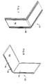
- the apparatus for mounting objects comprises a framing member 12, best illustrated in Figures 1 and 2 of the drawings.
- the mounting system includes a mounting frame 14, the mounting frame 14 including at least two framing members 12, joined together by a connecting piece or member 16, best shown in Figures 5, 6, 16a and 16b, a cable 18, a corner piece 20, best shown in Figure 7 and preferably a corner cover 22, best shown in Figures 9 and 10.
- a framing member 12 having a body portion 24, and two depending side walls 26 and 28.
- the body portion 24 is slightly convex.
- each slot having an entry channel 34 and 36 which leads into the base slot 38 and 40.
- Each T-shaped slot 32 is therefore defined by a body portion projection 42 and 44, a slot wall 46 and 48, and a part of the side wall 26 and 28, each of the side walls having a side wall projection 50 and 52.
- the slot walls 46 and 48 recess inwardly towards the center making the T-shaped slot asymmetrical, thus accommodating clearance to recess, out-of-view, cable 18.
- Each side wall 26, 28 further comprises an inwardly extending flange 54 which, with the remainder of the side wall 28 and the slot wall 48 defines a groove 56 which is continuous and runs down the entire the length of the framing member 12.
- the groove 56 has a widened end 58 at the closed end thereof.
- a plurality of framing members 12 may be connected to each other so as to define a frame which is adjustable in size, and may assume just about any shape or configuration which may be necessary depending upon the object which the mounting frame 14 is intended to support.
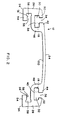
- Any two adjacent framing members 12 may be connected together by a connecting piece or member 16, best shown in Figures 5, 6, 16a and 16b of the drawings.
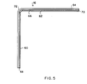
- the connecting piece or member 16 shown in Figure 5 has a first portion 60 and a second portion 62, the first and second portions being at substantially right angles to each other.
- the connecting piece or member 16 may have first and second portions which are other than at right angles to each other, depending on the shape of the frame that is to be constructed.
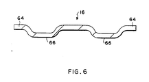
- the connecting member 16 may simply comprise a substantially plane or straight piece; in other words, such a connecting member has the first and second portions at 180° to each other. In this latter instance, the connecting member 16 will join a pair of adjacent framing members 12 where the framing members are intended to be continuous, and not to define an angle therebetween.
- the connecting piece 16 has a defined width for a particular framing member 12, and comprises a tongue 64 at each end thereof.
- the tongue 64 at each end of the connecting member 16 is adapted to be received in the groove 56 of the framing member 12.
- the connecting piece will be sufficiently wide so that it extends at least into the grooves 56 of the framing member 12 but would not be wider than the distance between the side walls 26 and 28 of the framing member.
- the connecting member is may be comprised of a series of corrugations 66, which impart additional strength to the connecting member, and limit the amount by which the connecting member may bend or give when under a load.
- Corrugations 66 are shown in Figures 5, 6, 15, and 16b to illustrate an embodiment of the preferred invention having connecting members 16 with increased strength (i.e., with corrugations 66).
- the preferred embodiment of connecting member 16 is shown in Figure 16a, and has corner corrugations 67 (rather than corrugations 66 running the entire length of connecting members 16). Corner corrugations 67 receive cables 250 which run across connecting members as described in more detail below.
- the first portion 60 of the connecting member 16 has a first end 68, while the second portion 62 of the connecting member 16 has a second end 70.
- the first end 68 is inserted into the grooves 56 and space extending therebetween of the framing member 12. Since the grooves 56 are continuous, the first portion 60 of the connecting piece 16 slides down along the grooves 56, and is able to do so at least until the bend 72 in the connecting member 16.
- a mounting frame 14 constructed between the framing members 12 and connecting members 16 joining such framing members 12 is variable in size, and the extent to which the first and second portions 60 and 62 of the connecting members 16 extend longitudinally between the continuous grooves 56 of the framing member 12 will in large part depend upon the size of the mounting frame 14 to be constructed, which is in turn dependent on the article or object which the mounting frame 14 is intended to support.
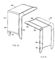
- FIGs 7 and 8 there is shown a cornerpiece 20 comprising a pair of flat surfaces 74 and 76 at substantially right angles to each other.
- Each flat surface 74 and 76 has an outer side 78, best shown in Figure 7, and an inner side 80 which can be seen in Figure 8.
- each of the flat surfaces 74 and 76 there is provided a flat hybrid synthetic/rubber or rubber-like material 82 which typically has a very high coefficient of friction.
- a suitable material is available under the trade name Santoprene (among others).
- the outer side 78 of the cornerpiece has running therealong a series of rib-like projections 84 extending from one end of the flat surface 74 to the opposite end of the flat surface 76.
- the cornerpiece 20 is intended to be located between the pair of adjacently connected framing members 12 and the object or article which is being mounted.
- the outer side 78 is, at least along some of its surface area, applied to a pair of adjacent framing members 12, while the inner side 80, and particularly the rubber-like material 82 thereof, is in contact with the object or article to be mounted.
- the mounting frame 14 is tightened, to be discussed further below, the cornerpiece 20 becomes firmly wedged and compressed between the mounting frame 14 and the object to be assembled.
- the rubber-like material 82 with the high coefficient of friction, prevents slipping or sliding of the article relative to the cornerpiece 20, especially when the cornerpiece 20 is pushed against the object or article with some force.
- the rib-like projections 84 facilitate a firm connection between the cornerpiece 20 and adjacent framing members 12 to further ensure that no slipping takes place.
- a corner cover 22 which, in the fully assembled mounting frame 14, essentially has an aesthetic or design function, and covers up the joined ends of the framing member 12 and the cornerpiece 20.
- the corner cover 22 has a pair of first and second walls 86 and 88 respectively, each of the walls 86 and 88 having a depending side wall 90.
- a number of tabs 92 are provided so that the corner cover 22 can be attached in a slide-on and snap-fit fashion to the framing members 12.
- the tabs 92 are located so as to snap behind side walls 26 and 28 at tab-connecting point 94 shown, for example, in Figure 2 of the drawings. While the tabs 92 constitute a secure fit, it is to be noted that they can also be removed since the cover corner 22 is generally comprised of a plastic material and can be sufficiently bent to remove the corner cover 22 should access or disassembly become necessary.
- the various components of the system of the present invention can be assembled to form a mounting frame 14 generally shown in Figure 15 of the drawings.
- four framing members 12a, 12b, 12c and 12d are arranged with respect to each other so as to form a rectangle.
- the desired size of the rectangle would be used to hold a monitor for a computer or a television set.
- the various framing members 12 can be arranged to form any desired shape or configuration, including an annular shape and configuration according to the article to be mounted.
- connecting piece 16a connects at right angles to each other the framing members 12a and 12d; connecting piece 16d connects the framing members 12d and 12c together at substantially right angles to each other; connecting piece 16c connects together mounting members 12c and 12b at substantially light angles to each other; and connecting piece 16b connects together the framing members 12a and 12b at substantially right angle to each other.
- the connecting members 16a-16d are capable of sliding movement within the continuous grooves 56 of their associated framing members 12a- 12d, so that, at least at this stage, there is some flexibility with respect to the size of the rectangle which the various framing members 12a-12d and connecting members 16a-16d may define. Furthermore, the extent of the flexibility can be varied according to the lengths of the first and second portions 60 and 62 of the connecting members 16. The longer the first and second portions 61 and 62 are, the more such first and second portions 60 and 62 may extend outside the track defined by the grooves 56 on the framing member 12, and the larger the rectangle defined by the various components may be. Range of movement may be defined and limited aesthetically by the length of the walls 86 and 88 of the corner cover. However, the framing system would still remain functionally operative if the connecting member end became visible.
- a cable 18 extends through each of the frame members 12a-12d and adjacent each of the connecting members 16a-16d.
- the slot base 38 and 40 of the continuous T-shaped slots 30 and 32 are adapted to receive the cable 18.
- the cable is inserted into the T-shaped slot through the entry channels 34 and 36, and thereafter moved into the inner portion of the base slots 38 and 40 respectively.
- the position of the cable 18 is shown in phantom lines in the base slots 38 and 40 of the T-shaped slots 30 and 32.
- the cable 18 extends through the base slot 38 and 40 of the T-shaped slots 30 and 32 of each of the framing members 12a-12d, and then passes over the outer side of each connecting piece 16a-16d. It is prevented from any substantial movement as it passes over each connecting piece 16a-16d by virtue of corner corrugations 67 (see Figure 16a) or corrugations 66 (see Figures 6 and 16b) (depending upon which type of connecting piece 16 is used).
- corner corrugations 67 and corrugations 66 provide two troughs, one on each side of the connecting piece 16, and each trough is designed to receive the cable 18.
- the trough offers a path for the cable 18 which continues off from the base slots 38 and 40.
- the trough also serves to initially position and maintain the position of the cable 18 in the location allocated therefor.
- Cable 18 is preferably provided with a cable tensioning apparatus.
- a cable tensioning apparatus is preferable since it is possible that the cable may, over time, slip or loosen.
- the cable has constant tension provided by the force of a compression spring to eliminate the potential for slippage or loosening over time.
- the compression spring also provides additional travel, essential to facilitate adequate travel during tensioning.
- cable 250 runs through each of framing members 12a-12d and passes over connecting pieces 16a-16d (as described above), and is secured at both ends within tensioner 252 (see Figure 11).
- Tensioner 252 preferably has two opposing sides 254, 256 through which pass cable holes 258, 260 which receive opposite ends of cable 262, 264, respectively.
- Tensioner 252 is preferably housed within a tensioner hole 266 within framing member 12, and is seated upon the wall 56 (see also, Figure 2) of each continuous groove 56 in framing member 12.
- tensioner 252 is held in place within tensioner hole 266 by being covered by mounting system 138 (see Figure 15) when the mounting frame is mounted on mounting system 138.
- mounting system 138 see Figure 15
- threaded fasteners (not shown) of a conventional mounting system 138 are passed through threaded mounting holes 269 flanking tensioner hole 266 in framing member 12. (Note that in Figure 11, only two of four mounting holes 269 are shown on one side of tensioner hole 266).
- Tensioner 252 may be of any shape which at least has a body to which cable 250 is attachable (e.g., through cable holes as described in more detail below) and which is held within an appropriately-shaped tensioner hole 266 (preferably matching the shape of the tensioner).
- the tensioner may simply be a single bar held in place within a tensioner hole and through which all cable holes pass which are necessary for securing both ends of a cable (as described below).
- the manner in which the various shapes and types of tensioners are seated within tensioner holes may vary considerably, and depend largely upon the shape of the tensioner.
- tensioner hole location in the preferred embodiment is in the center of a framing member and beneath a conventional mounting system 138, the particular location of a tensioner hole may also vary. In fact, the tensioner hole and tensioner held therein may be located on any framing member 12 of a mounting frame 14, and need not necessarily be located under a conventional mounting system 138.
- Tensioner 252 is preferably made from aluminum. However, tensioner 252 may be made of a wide variety of materials offering the strength necessary to hold and secure both ends of cable 250 when fully loaded. Alternative materials include steel, iron, titanium, and other metals, composites, ceramics, plastics, wood, etc.
- One end 262 of cable 250 is preferably secured in one tensioner side 254 as follows.
- Cable 250 is snaked through a pair of adjacent cable holes 258 in tensioner side 254.
- One of the cable holes 258 has two setscrew holes joined thereto for passing setscrews 270 therethrough.
- the adjacent cable hole 258 has one setscrew hole joined thereto for passing setscrew 274 therethrough.
- the U-shaped loop made by snaking cable 250 through cable holes 258 (as described above and illustrated in Figure 11) and securing cable end 262 therein with setscrews in each cable hole 258 provides a reliable manner in which to secure cable end 262 to tensioner 252.
- more or fewer setscrews may be used for cable holes 258.
- Cable 250 may even be passed through only one cable hole and secured therein using one setscrew.
- the use of multiple (i.e. three) setscrews in multiple cable holes is preferred, since such a design provides for additional strength and safety.
- other conventional fasteners and fastening methods may be used to clamp cable 250 to tensioner side 254.
- cable 250 may be clamped in other manners, welded, tied, or crimped in place, ferrules may be crimped on cable end 262 so that it may not pass out of a cable hole, etc. It should be noted, however, that some securement manners do not provide the advantage of cable releasability realized in the preferred embodiment (setscrews 270, 274 may be loosened to remove cable 250 entirely from tensioner 266).
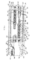
- the opposite end 264 of cable 250 preferably is attached to tensioner 252 by a tension spring assembly 276.
- Tension spring assembly 276 preferably includes threaded tube 278, nut 280, washer 282, and spring 286.
- Threaded tube 278 preferably extends within cable hole 260 in tensioner side 256 and is loosely held therein (i.e., may slide therein).
- Cable end 264 extends fully through threaded tube 278 in cable hole 260 and has one or more (preferably two) ferrules 288 crimped to its terminal end. Two ferrules are preferred (rather than one) to ensure that cable end 264 is firmly secured within tension spring assembly 276.
- Ferrules 288 prevent cable end 264 from passing through threaded tube 278 not only because ferrules 288 are preferably larger than the inside diameter of threaded tube 278, but also because one of the ferrules 288 abut against nut 280 threaded onto threaded tube 278.
- Spring 286 preferably surrounds threaded tube 278 and is kept in place on tension spring assembly 276 by abutting washer 282 on one end (which itself abuts nut 280) and tensioner side 256 on another end.
- cable 250 may be tightened by adjusting tension spring assembly 276.
- tension spring assembly 276 Specifically, by turning nut 280, threaded tube 278 is either drawn into or allowed to be pulled out of cable hole 260, depending upon which direction nut 280 is turned.
- flats 281 are preferably provided on the ends of threaded tube 278 for a user to hold (by using a wrench, for example) while adjusting nut 280. By using flats 281 to hold threaded tube 278, damage to cable 250 caused by twisting when nut 280 is turned is avoided.
- tension spring 286 which preferably is selected to provide a constant compression force over a wide range of spring compressions.
- Spring 286 thereby also acts to provide a constant tension force on cable 250 over a range of cable lengths. This feature is particularly valuable when mounting frame parts settle or shift over time, thereby causing slight slack in cable 250. Such slack is picked up by tension spring assembly 276.
- spring 286 may be a leaf spring, coil spring, etc. attached to cable end 264 and to tensioner 252 in a conventional manner. Adjustment of alternative springs are well known to those skilled in the art and are not discussed further herein.
- mounting frame 14 and tensioner 252 are preferably provided with two cables 250 and tension spring assemblies 276.
- the inclusion of two (or even more) separate cables 250 and tension spring assemblies 276 increases the reliability of mounting frame 14. In particular, if one cable 250 and tension spring assembly 276 fails, other cables 250 and tension spring assemblies 276 act as backup elements to keep a mounted unit safely secured within mounting frame 14.
- cables 250 preferably pass from cable holes 258, 260 to a position beneath framing member 12.
- cable holes 290 are preferably provided in slot walls 46, 48 of framing member 12.
- Cable 318 has a first end 396 and a second end 398 which joins to the first end 396 in any suitable matter.
- Cable 318 is preferably provided with tensioning apparatus 300, which may include a ring clamp 302 near the first end 396 of the cable 318.
- tensioning apparatus 300 may include a ring clamp 302 near the first end 396 of the cable 318.
- a first tie 304 with a hook 306 and 308 at each end thereof is provided. The hook 306 engages the ring clamp 302, while the hook 308 extends through a compression spring 310, around which it attaches.
- a second tie 312, also having a hook 314 and 316 at each end is provided.
- the hook 314 of the second tie 312 extends through and around the compression spring 310, while the hook 316 on the second tie 312 is available for connection to the second end 398 of the cable 318.
- the first and second ends 396 and 398 of the cable 318 may be attached in a fixed manner to a part of the mounting frame.
- the framing members 12a-12d and connecting pieces or members 16a-16d are assembled with respect to each other as shown in Figure 15, and two cables are threaded through the framing members 12a-12d and connecting members 16a-16d as described above.
- the cable is held loosely, so that the area defined by the mounting frame 14 is slightly larger than the object to be mounted.
- the tensioning means 100, 300 is intended to incorporate two independently functioning cable assemblies, either one of which will support the object at the maximum rated load, should one cable assembly not operate at any time.
- a cornerpiece 20 is placed at each of the four corners of the object to be mounted.
- the rubber-like material 82 is permanently affixed to the cornerpiece 20.
- Each cornerpiece 20, mounted at a corner of the object will remain in contact therewith and is unlikely to slip because of the high coefficient of friction created by the rubber-like material 82.
- the object and mounting frame 14 With each cornerpiece in position, the object and mounting frame 14 are brought into registry with each other so that the mounting frame surrounds the object at those points where the connecting members are located. In this position, the mounting frame 14 is ready to be tightened and secured so that the object is firmly held therein.
- the cable is tightened drawing the framing members 12a-12d and connecting members 16a- 16d more closely and more tightly together, and bringing compressive pressure on the object through surface contact with the rubber-like material 82 on the cornerpieces 20.
- the cornerpieces 20 and rubber-like material 82 will be firmly wedged between the object being mounted and the mounting frame 14 defined by the framing members 12a-12d and connecting members 16a- 16d.
- the cable ends are secured so that further movement of the cable is not permitted.
- the object such as a television monitor, therefore now has a mounting frame 14 securely tightened about its perimeter.
- the mounting frame when used to mount, for example, a television monitor, is intended to be positioned in line with the television monitor's center of gravity situated in almost all cases at the very front of the television monitor enclosure.
- a corner cover 22 may be placed on and snapped into position at each corner so as to cover the join between the adjacent framing members 12 and to cover the particular connecting piece 16.
- the corner cover 22 thus provides an appealing appearance and finishes off, from an aesthetic point of view, the mounting frame 14.
- the corner covers 22 have a snap-fit connection to the frame member 12, with the tabs 92 of the corner cover 22 fitting around the tab connecting point 94 of the framing member 12.
- the corner cover 22 can be easily removed, being made of plastic material, for appropriate adjustment or disassembly of the mounting frame 14 as necessary.
- the entire mounting frame is intended to present a low, unobtrusive profile in relation to the object or device to be mounted.
- the framing members 12 and connecting members 16 are generally comprised of aluminum or steel, particularly where the object to be mounted is heavy. For smaller, lightweight objects, these components may be comprised of strong plastic such as polyurethane and/or polycarbonates.
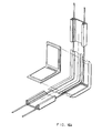
- FIG. 13 shows a second preferred embodiment of a cable tensioning apparatus.
- a base plate 418 is provided which is adapted to lie below the body portion 24 of the framing member 12. Thus, the base plate 418 will typically abut or be adjacent to the inner surface 120 of the body portion 24.
- Each cable wheel 422 and 424 incorporates a ratchet gear wheel 426 and 428 and a corresponding pawl 430 and 432.
- a pawl spring 434 Associated with each pawl 430 and 432 is a pawl spring 434.
- the body portion 24 of the framing member 12 will have holes therein corresponding to the position of the hub 436 of each wheel 422 and 424, and with the use of appropriate tools, extending through the hole, the cable wheels 422 and 424 can be turned to effect the necessary tightening and tensioning of the cable to securely hold the mounting frame 14 in the desired position.
- Figure 14 shows a third embodiment of a cable tensioning apparatus.
- conventional cable wheels can be tightened to effect the necessary tension in the cable, and the wheels thereafter bolted securely to the base plate 518.
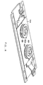
- FIG 17 there is shown a second embodiment of a framing member 212, which is in all material aspects identical to the framing member 12 shown in Figures 1-3, except that the side walls 226 and 228 are shorter, and no flange 54 is provided. There will, of course, be no groove 56.
- a mounting member of the type shown in Figure 17 may be used for a different mounting purpose.
- an extended extrusion of the framing member 212 may be bolted to a wall, and an adapter plate 214 is structured so as to be received and slide within the T-shaped slots 230 and 232.
- Each adapter plate 214 has a pair of L-shaped projections 216 which are spaced and designed to slide freely in the continuous T-shaped slots 230 and 232.
- Each adapter plate 214 includes a fixing means which may comprise a bolt in a threaded hole. As the bolt is tightened, it will apply pressure to the body portion, thus fixing the adapter plate with respect to the body portion. The adapter plate is then available for use, and, depending on its shape and configuration, will either support or permit to be mounted desired objects.
- the framing member 12 shown in Figures 1-3 is also capable of mounting on a wall so that an adapter plate 214 may slide within the T-shaped slots 30 and 32.
- an advantage of mounting a framing member 12 of the type shown in Figures 1-3 against a wall is that the mounting pieces may be located behind the body portion, namely, between the body portion and the wall, and therefore not be visible when mounted.
- An adapter may therefore comprise a plate which slides in and is received in the continuous grooves 56, the plate being mounted to the wall. Once the plate is mounted to the wall, the framing member 12 is located over the plate, and one or more such plates may hold the framing member 12 in position.
- the plate may be integrated as part of a die-cast and cap fitting that both dresses-down the end of framing member 12 and slides into the continuous grooves 56 of the framing member 12.
- the framing member 12 in conjunction with connecting members 16 of different angle, can be used to create a frame of just about any size and shape, and therefore be easily adapted to mounting the object desired.
- the articles or objects which may be mounted by a system described in the present invention include computer monitors, television sets, cameras, VCRs, speakers, computers, printers, microwave ovens and a host of other electronic equipment.
- the components of the present invention additionally provide an aesthetically pleasing, low-profile frame which would, from a design point of view, enhance the appearance of a residential media center, home theaters or any other environment in which it is located.
- the invention has applications not only in residential media centers, home theaters but also with respect to commercial displays in retail outlets, positioning of electronic equipment in theaters, cinemas, broadcast and production facilities and corporate boardrooms and the like.
- the mounting frame 14 is attached to any suitable and/or conventional mounting system 138, as shown in Figure 15 of the drawings.
- desired mounting systems which may comprise ball and socket connections or elbow joints, the frame, together with the object therein, can be attached to a wall, ceiling or floor so that its position is exactly as desired.
- the system also has certain advantages particularly with respect to television sets and computer monitors.
- the mounting frame 14 can be located about that portion of the object through which the center of gravity passes. When mounted in this way, the object will be relatively well “balanced” within the mounting frame, and therefore unnecessary load due to overbalancing or uncentered mounting can be avoided.
- This system also provides a particularly secure connection with the object.
- the object mounted will not easily be displaced from the mounting frame by any unintentional knock or shaking, or any violent motion produced by an earthquake.
- the use of two fully independent cable systems in the mounting frame is an added safety feature since, if one cable were to become loose or otherwise fail in its ability to keep the mounting frame together, the other cable would still continue to function and essentially hold the mounting frame together.
- the system is also exceptionally flexible in that objects mounted can be moved, for example, from one residence to another, without actually dismantling the mounting frame 14 from the object mounted. Rather, the object will remain in the frame, and the entire structure disengaged from the floor, wall or ceiling, so that when moving the system a minimal amount of deconstruction and reassembling is necessary.
- the framing member 12 may have a configuration or shape other than that described.
- the body portion need not be arcuate, the continuous T-shaped slots may be of slightly different shape, with other small constructional changes.
- any suitable means for fastening and/or tensioning the cable may be provided.
- the cornerpiece 20 may be omitted, or be incorporated into the framing member 12 and/or connecting piece 16 which may have extensions or projections for the purpose of frictionally engaging the object to be mounted.
Landscapes
- Engineering & Computer Science (AREA)
- General Engineering & Computer Science (AREA)
- Mechanical Engineering (AREA)
- Clamps And Clips (AREA)
- Supports For Pipes And Cables (AREA)
- Electric Cable Arrangement Between Relatively Moving Parts (AREA)
- Installation Of Indoor Wiring (AREA)
Applications Claiming Priority (2)
| Application Number | Priority Date | Filing Date | Title |
|---|---|---|---|
| US09/055,600 US6102350A (en) | 1995-12-28 | 1998-04-06 | Apparatus for mounting objects, including tension member |
| US55600 | 1998-04-06 |
Publications (2)
| Publication Number | Publication Date |
|---|---|
| EP0949445A2 true EP0949445A2 (de) | 1999-10-13 |
| EP0949445A3 EP0949445A3 (de) | 2002-01-16 |
Family
ID=21998944
Family Applications (1)
| Application Number | Title | Priority Date | Filing Date |
|---|---|---|---|
| EP99302617A Withdrawn EP0949445A3 (de) | 1998-04-06 | 1999-04-01 | Halterungsvorrichtung für Gegenstände |
Country Status (3)
| Country | Link |
|---|---|
| US (1) | US6102350A (de) |
| EP (1) | EP0949445A3 (de) |
| CA (1) | CA2267855A1 (de) |
Cited By (1)
| Publication number | Priority date | Publication date | Assignee | Title |
|---|---|---|---|---|
| GB2475977A (en) * | 2009-12-04 | 2011-06-08 | Robert Terence Portus | Height and rotatably adjustable support device for a display |
Families Citing this family (15)
| Publication number | Priority date | Publication date | Assignee | Title |
|---|---|---|---|---|
| US7077373B1 (en) | 2000-01-05 | 2006-07-18 | Da-Lite Screen Co., Inc. | Mount for TV monitor |
| US6933931B2 (en) * | 2002-08-23 | 2005-08-23 | Ceronix, Inc. | Method and apparatus of position location |
| US6986491B2 (en) | 2002-11-12 | 2006-01-17 | Knape & Vogt Manufacturing Co. | CPU holder |
| US20080067298A1 (en) * | 2006-03-17 | 2008-03-20 | Rob Mossman | Video monitor mount |
| WO2007112419A2 (en) * | 2006-03-27 | 2007-10-04 | Southco, Inc. | Display mounting apparatus |
| WO2009033213A1 (en) * | 2007-09-11 | 2009-03-19 | Dazhi Huang | Length adjustable curtain track system |
| DE202009010894U1 (de) * | 2009-08-19 | 2009-12-24 | Geller, Wolfgang Peter | Transportabler Lichtmanipulator |
| CN103097978B (zh) | 2010-07-08 | 2016-08-10 | 索斯科公司 | 显示器支撑装置 |
| US9062816B2 (en) | 2012-01-06 | 2015-06-23 | Wirepath Home Systems, Llc | Tilt head assemblies and methods of using the same |
| USD743969S1 (en) | 2013-10-16 | 2015-11-24 | Wirepath Home Systems, Llc | Single arm articulating mount for an electronic display |
| USD747724S1 (en) | 2013-12-20 | 2016-01-19 | Wirepath Home Systems, Llc | Dual arm articulating mount for an electronic display |
| EP3933247B1 (de) | 2016-03-07 | 2023-04-19 | Southco, Inc. | Stützarmbaugruppe für eine anzeige zur montage einer anzeige |
| US10414323B2 (en) * | 2016-09-14 | 2019-09-17 | Sarah Mason Scott | Hand-driven ratchet strap assist device |
| CN108799397B (zh) * | 2018-08-14 | 2024-08-06 | 上海海事大学 | 一种船用减震套架 |
| CN119309120B (zh) * | 2024-12-16 | 2025-03-21 | 国网山东省电力公司禹城市供电公司 | 一种基于电网数字化应用的红外检测装置 |
Family Cites Families (38)
| Publication number | Priority date | Publication date | Assignee | Title |
|---|---|---|---|---|
| US542966A (en) * | 1895-07-16 | Wire fence | ||
| BE405803A (de) * | ||||
| DE181133C (de) * | 1900-01-01 | |||
| US565916A (en) * | 1896-08-18 | Wire fence | ||
| DE457013C (de) * | 1928-03-07 | Julius Klement | Rahmenspannvorrichtung | |
| US2204493A (en) * | 1938-02-09 | 1940-06-11 | James N Henry | Curtain rod |
| CH240092A (de) * | 1945-05-02 | 1945-11-30 | Perren Anselm | Gepäckhalter. |
| US2608383A (en) * | 1948-06-15 | 1952-08-26 | Thomas H Edelblute | Load binder |
| US2539997A (en) * | 1949-09-06 | 1951-01-30 | Lester R Graves | Car top fastener for boats and other articles |
| US2611949A (en) * | 1949-10-08 | 1952-09-30 | Wanamaker Seth | Toilet tank fitting holding tool |
| US2831808A (en) * | 1955-10-14 | 1958-04-22 | George J Esseff | Article supporting rack |
| CH452154A (de) * | 1967-04-26 | 1968-05-31 | Alusuisse | Rahmenkonstruktion bei Skelettbauweise |
| US3451153A (en) * | 1967-05-08 | 1969-06-24 | John A Dohanyos | Adjustable framing device |
| US3784043A (en) * | 1968-11-29 | 1974-01-08 | M Presnick | Lightweight collapsible structures |
| US3796404A (en) * | 1972-04-20 | 1974-03-12 | States Steamship Co | Apparatus for alternatively securing irregular cargo and standard shipping containers |
| US4074811A (en) * | 1975-10-15 | 1978-02-21 | Filak Andrew M | Multi-level knock-down framework structure for supporting a plurality of objects |
| US4027866A (en) * | 1975-12-29 | 1977-06-07 | Arthur Ruggiero | Multi-face clamp for manufacturing or regluing of drawers, chairs or the like |
| US4031796A (en) * | 1976-04-28 | 1977-06-28 | Teledyne, Inc. | Solenoid mounting assembly for musical keyboard |
| US4356648A (en) * | 1981-05-08 | 1982-11-02 | Rupp Industries, Inc. | Framing system for display panels |
| US4450655A (en) * | 1982-08-25 | 1984-05-29 | Rosenthal Michael R | Vertically slotted panel |
| GB2200491B (en) * | 1987-01-22 | 1990-06-06 | Bailey Concepts Limited | Suspension device for display units and the like |
| US4842236A (en) * | 1987-04-16 | 1989-06-27 | Yonts James T | Spring-loaded tiedown apparatus for boats, campers and other cargo |
| US4831804A (en) * | 1987-09-17 | 1989-05-23 | Thermal Profiles, Inc. | Window frame apparatus |
| DE3805422C1 (de) * | 1988-02-22 | 1988-12-15 | Rittal-Werk Rudolf Loh Gmbh & Co Kg, 6348 Herborn, De | |
| GB2231995B (en) * | 1989-05-20 | 1993-04-28 | Signco Ltd | Framing |
| US4924649A (en) * | 1989-07-13 | 1990-05-15 | Innovative Building Products, Inc. | Corner assembly for a skylight frame |
| US5064161A (en) * | 1991-01-10 | 1991-11-12 | Anderson Timothy W | Universal ceiling mount assembly for television monitor |
| US5102081A (en) * | 1991-03-15 | 1992-04-07 | Barchus David D | Telescopable pivotal mounting assembly |
| US5165644A (en) * | 1991-07-25 | 1992-11-24 | Thomas Allen | Mounting apparatus for a video display |
| US5161789A (en) * | 1991-08-27 | 1992-11-10 | Rogers Winston L | Universal clamping device |
| US5310152A (en) * | 1992-01-08 | 1994-05-10 | Lucasey Manufacturing Company | Television mounting support with removable lifting assembly |
| US5402557A (en) * | 1993-05-03 | 1995-04-04 | Dalen; Thomas M. | Dynamic self-adjusting tie-down device for transportable items |
| US5400993A (en) * | 1993-08-17 | 1995-03-28 | Hamilton; Clifton | Adjustable overhead suspension apparatus for TV and VCR |
| US5393025A (en) * | 1993-10-21 | 1995-02-28 | Franklin; Harry C. | Cabinet mounting harness |
| US5411244A (en) * | 1994-03-04 | 1995-05-02 | Turner; Tommy P. | Clamp using elastic tension member |
| US5538214A (en) * | 1994-07-27 | 1996-07-23 | Sinila; Alexander | Locking accessory support apparatus |
| US5927668A (en) * | 1995-12-28 | 1999-07-27 | Omni Mount Systems, Inc. | Adjustable framing support system |
| DE19734350C1 (de) * | 1997-08-08 | 1998-11-19 | Eckhard Schirmer | Geschlossener Trag- und Halterahmen |
-
1998
- 1998-04-06 US US09/055,600 patent/US6102350A/en not_active Expired - Lifetime
-
1999
- 1999-03-31 CA CA002267855A patent/CA2267855A1/en not_active Abandoned
- 1999-04-01 EP EP99302617A patent/EP0949445A3/de not_active Withdrawn
Non-Patent Citations (1)
| Title |
|---|
| None |
Cited By (1)
| Publication number | Priority date | Publication date | Assignee | Title |
|---|---|---|---|---|
| GB2475977A (en) * | 2009-12-04 | 2011-06-08 | Robert Terence Portus | Height and rotatably adjustable support device for a display |
Also Published As
| Publication number | Publication date |
|---|---|
| US6102350A (en) | 2000-08-15 |
| CA2267855A1 (en) | 1999-10-06 |
| EP0949445A3 (de) | 2002-01-16 |
Similar Documents
| Publication | Publication Date | Title |
|---|---|---|
| US5927668A (en) | Adjustable framing support system | |
| US6102350A (en) | Apparatus for mounting objects, including tension member | |
| US10527219B2 (en) | Mounting track for retaining a mount assembly | |
| US8191840B2 (en) | T-channel fixture-mounting pole clamp | |
| CA2470525C (en) | Universal wall mounting bracket | |
| US7883065B2 (en) | Mounting bracket | |
| US5672003A (en) | Universal track light mounting system | |
| US7845599B2 (en) | Mounting coupling for sprinkler support system | |
| US6554527B1 (en) | Mounting assembly | |
| US20050017133A1 (en) | Pipe support apparatus | |
| US20190376645A1 (en) | Support assembly for mounting structures onto vertically disposed objects including televisions and video monitors | |
| US20030185643A1 (en) | Flexible bridge for a strut nut | |
| CA2267858A1 (en) | Continuously adjustable surface mounting system | |
| CA2129742A1 (en) | Cleat | |
| CA2163512A1 (en) | Emergency Lighting Connections | |
| KR102143967B1 (ko) | 찬넬용 체결장치 | |
| WO2008154564A1 (en) | Clamp and seismic sway brace | |
| US5544865A (en) | Rail support bracket | |
| US6508441B1 (en) | Sway brace | |
| CN111609018A (zh) | 结构紧固件 | |
| JP2017057704A (ja) | ブレース連結金具 | |
| US11808404B1 (en) | Leveraging clamp device | |
| US11655841B2 (en) | Structural fastener | |
| US12152619B2 (en) | Leveraging clamp device and methods of clamping | |
| KR100396594B1 (ko) | 천장 걸이용 디스플레이 장치의 고정 및 각도 조절장치 |
Legal Events
| Date | Code | Title | Description |
|---|---|---|---|
| PUAI | Public reference made under article 153(3) epc to a published international application that has entered the european phase |
Free format text: ORIGINAL CODE: 0009012 |
|
| AK | Designated contracting states |
Kind code of ref document: A2 Designated state(s): AT BE CH CY DE DK ES FI FR GB GR IE IT LI LU MC NL PT SE |
|
| AX | Request for extension of the european patent |
Free format text: AL;LT;LV;MK;RO;SI |
|
| PUAL | Search report despatched |
Free format text: ORIGINAL CODE: 0009013 |
|
| AK | Designated contracting states |
Kind code of ref document: A3 Designated state(s): AT BE CH CY DE DK ES FI FR GB GR IE IT LI LU MC NL PT SE |
|
| AX | Request for extension of the european patent |
Free format text: AL;LT;LV;MK;RO;SI |
|
| RIC1 | Information provided on ipc code assigned before grant |
Free format text: 7F 16M 13/00 A, 7F 16M 11/04 B |
|
| 17P | Request for examination filed |
Effective date: 20020708 |
|
| AKX | Designation fees paid |
Free format text: AT BE CH CY DE DK ES LI |
|
| AXX | Extension fees paid |
Free format text: AL PAYMENT 20020708;LT PAYMENT 20020708;LV PAYMENT 20020708;MK PAYMENT 20020708;RO PAYMENT 20020708;SI PAYMENT 20020708 |
|
| RBV | Designated contracting states (corrected) |
Designated state(s): AT BE CH CY DE DK ES FI FR GB GR IE IT LI LU MC NL PT SE |
|
| 17Q | First examination report despatched |
Effective date: 20040608 |
|
| STAA | Information on the status of an ep patent application or granted ep patent |
Free format text: STATUS: THE APPLICATION IS DEEMED TO BE WITHDRAWN |
|
| 18D | Application deemed to be withdrawn |
Effective date: 20041221 |