EP0948690B1 - A cylinder lock - Google Patents
A cylinder lock Download PDFInfo
- Publication number
- EP0948690B1 EP0948690B1 EP97911566A EP97911566A EP0948690B1 EP 0948690 B1 EP0948690 B1 EP 0948690B1 EP 97911566 A EP97911566 A EP 97911566A EP 97911566 A EP97911566 A EP 97911566A EP 0948690 B1 EP0948690 B1 EP 0948690B1
- Authority
- EP
- European Patent Office
- Prior art keywords
- plug
- profiled element
- key
- slot
- cylinder lock
- Prior art date
- Legal status (The legal status is an assumption and is not a legal conclusion. Google has not performed a legal analysis and makes no representation as to the accuracy of the status listed.)
- Expired - Lifetime
Links
- 238000004873 anchoring Methods 0.000 claims description 9
- 239000000463 material Substances 0.000 claims description 9
- 229910001220 stainless steel Inorganic materials 0.000 claims description 4
- 239000010935 stainless steel Substances 0.000 claims description 4
- 230000004323 axial length Effects 0.000 claims description 3
- 230000002093 peripheral effect Effects 0.000 claims description 2
- 230000037431 insertion Effects 0.000 claims 1
- 238000003780 insertion Methods 0.000 claims 1
- 229910000760 Hardened steel Inorganic materials 0.000 description 3
- 238000010276 construction Methods 0.000 description 2
- 238000005553 drilling Methods 0.000 description 2
- 229910001369 Brass Inorganic materials 0.000 description 1
- 239000010951 brass Substances 0.000 description 1
- 230000001788 irregular Effects 0.000 description 1
- 238000000034 method Methods 0.000 description 1
- 230000009993 protective function Effects 0.000 description 1
- 238000000926 separation method Methods 0.000 description 1
Images


Classifications
-
- E—FIXED CONSTRUCTIONS
- E05—LOCKS; KEYS; WINDOW OR DOOR FITTINGS; SAFES
- E05B—LOCKS; ACCESSORIES THEREFOR; HANDCUFFS
- E05B15/00—Other details of locks; Parts for engagement by bolts of fastening devices
- E05B15/08—Key guides; Key pins ; Keyholes; Keyhole finders
-
- E—FIXED CONSTRUCTIONS
- E05—LOCKS; KEYS; WINDOW OR DOOR FITTINGS; SAFES
- E05B—LOCKS; ACCESSORIES THEREFOR; HANDCUFFS
- E05B15/00—Other details of locks; Parts for engagement by bolts of fastening devices
- E05B15/16—Use of special materials for parts of locks
- E05B15/1614—Use of special materials for parts of locks of hard materials, to prevent drilling
-
- E—FIXED CONSTRUCTIONS
- E05—LOCKS; KEYS; WINDOW OR DOOR FITTINGS; SAFES
- E05B—LOCKS; ACCESSORIES THEREFOR; HANDCUFFS
- E05B9/00—Lock casings or latch-mechanism casings ; Fastening locks or fasteners or parts thereof to the wing
- E05B9/04—Casings of cylinder locks
-
- Y—GENERAL TAGGING OF NEW TECHNOLOGICAL DEVELOPMENTS; GENERAL TAGGING OF CROSS-SECTIONAL TECHNOLOGIES SPANNING OVER SEVERAL SECTIONS OF THE IPC; TECHNICAL SUBJECTS COVERED BY FORMER USPC CROSS-REFERENCE ART COLLECTIONS [XRACs] AND DIGESTS
- Y10—TECHNICAL SUBJECTS COVERED BY FORMER USPC
- Y10T—TECHNICAL SUBJECTS COVERED BY FORMER US CLASSIFICATION
- Y10T70/00—Locks
- Y10T70/70—Operating mechanism
- Y10T70/7441—Key
- Y10T70/7486—Single key
- Y10T70/7508—Tumbler type
- Y10T70/7559—Cylinder type
- Y10T70/7638—Cylinder and plug assembly
-
- Y—GENERAL TAGGING OF NEW TECHNOLOGICAL DEVELOPMENTS; GENERAL TAGGING OF CROSS-SECTIONAL TECHNOLOGIES SPANNING OVER SEVERAL SECTIONS OF THE IPC; TECHNICAL SUBJECTS COVERED BY FORMER USPC CROSS-REFERENCE ART COLLECTIONS [XRACs] AND DIGESTS
- Y10—TECHNICAL SUBJECTS COVERED BY FORMER USPC
- Y10T—TECHNICAL SUBJECTS COVERED BY FORMER US CLASSIFICATION
- Y10T70/00—Locks
- Y10T70/70—Operating mechanism
- Y10T70/7441—Key
- Y10T70/7486—Single key
- Y10T70/7508—Tumbler type
- Y10T70/7559—Cylinder type
- Y10T70/7667—Operating elements, parts and adjuncts
- Y10T70/7684—Plug
-
- Y—GENERAL TAGGING OF NEW TECHNOLOGICAL DEVELOPMENTS; GENERAL TAGGING OF CROSS-SECTIONAL TECHNOLOGIES SPANNING OVER SEVERAL SECTIONS OF THE IPC; TECHNICAL SUBJECTS COVERED BY FORMER USPC CROSS-REFERENCE ART COLLECTIONS [XRACs] AND DIGESTS
- Y10—TECHNICAL SUBJECTS COVERED BY FORMER USPC
- Y10T—TECHNICAL SUBJECTS COVERED BY FORMER US CLASSIFICATION
- Y10T70/00—Locks
- Y10T70/70—Operating mechanism
- Y10T70/7441—Key
- Y10T70/7915—Tampering prevention or attack defeating
- Y10T70/7921—Armoring
-
- Y—GENERAL TAGGING OF NEW TECHNOLOGICAL DEVELOPMENTS; GENERAL TAGGING OF CROSS-SECTIONAL TECHNOLOGIES SPANNING OVER SEVERAL SECTIONS OF THE IPC; TECHNICAL SUBJECTS COVERED BY FORMER USPC CROSS-REFERENCE ART COLLECTIONS [XRACs] AND DIGESTS
- Y10—TECHNICAL SUBJECTS COVERED BY FORMER USPC
- Y10T—TECHNICAL SUBJECTS COVERED BY FORMER US CLASSIFICATION
- Y10T70/00—Locks
- Y10T70/70—Operating mechanism
- Y10T70/7441—Key
- Y10T70/7915—Tampering prevention or attack defeating
- Y10T70/7955—Keyhole guards
- Y10T70/796—Portable
-
- Y—GENERAL TAGGING OF NEW TECHNOLOGICAL DEVELOPMENTS; GENERAL TAGGING OF CROSS-SECTIONAL TECHNOLOGIES SPANNING OVER SEVERAL SECTIONS OF THE IPC; TECHNICAL SUBJECTS COVERED BY FORMER USPC CROSS-REFERENCE ART COLLECTIONS [XRACs] AND DIGESTS
- Y10—TECHNICAL SUBJECTS COVERED BY FORMER USPC
- Y10T—TECHNICAL SUBJECTS COVERED BY FORMER US CLASSIFICATION
- Y10T70/00—Locks
- Y10T70/80—Parts, attachments, accessories and adjuncts
- Y10T70/8432—For key-operated mechanism
- Y10T70/8649—Keyhole covers
Definitions
- the present invention relates to a cylinder lock of the kind defined in the preamble of Claim 1.
- Cylinder locks of the kind that include a profiled element fitted to the front end of the lock plug have the advantage of enabling the major part of the key slot formed in the plug to be configured to fit a large number of keys belonging to one and the same key-family, while separation between various individuals in the family is achieved by configuring the key slot of the profiled element to the appearance specific to the individual concerned, i.e. only an intended key can be inserted.
- the profiled element can also be made of any chosen material, which may be different from the brass material from which the main part of the lock plug is normally made.
- the profiled element may be made of stainless steel or hardened steel.
- hardened steel also incorporates in the lock construction separate protection against an attempt to drill into the lock, which obviates the need to provide a separate drill-guard in front of the plug, for instance in the form of a separate element in the lock construction.
- a profiled element of this kind is that it can be replaced.
- the key-slot opening becomes worn as a result of very frequent use of the key, it is not necessary to replace the whole of the cylinder plug or the lock cylinder, since it will normally be sufficient to replace solely the profiled element.
- This replaceability of the profiled element can also be of value in cases where it is desired to prevent an unauthorized person using a key to which he/she has access or possesses, for instance after having stolen the key, gaining entry to a locked room. This can be achieved simply by replacing the profiled element, without needing to replace the entire lock cylinder.
- SE,B,8403605-2 (Wärtsilä) teaches a lock system that includes a plurality of different groups of cylinder locks that incorporate rotatable latch discs and a plurality of different types of key for the various lock groups with mutually deviating key profiles, wherewith the utility of one key profile in one lock group is determined by the latch discs of the lock and by the configuration of the key-receiving opening in the latch discs.
- One and the same key will have at least two different profiles disposed axially one after the other.
- This lock system can thus be said to include a plurality of profiled elements of the kind to which this document pertains, arranged one after the other in the lock plug. These profiled elements are not therefore intended to safeguard the plug from an attempt to force the lock from outside, for instance by drilling into the plug. Neither can the profiled element be replaced as readily as that described in the aforegoing, when the need arises.
- US,A,3 736 780 (Singer) describes a cylinder lock in which the profiled element is attached to the lock plug by means of externally accessible screws.
- a separate cover plate may optionally be crimped onto the profiled element, to enhance the aesthetic appearance of the lock. This arrangement, however, provides no real protection against forcing of the lock from the outside. The actual cover plate and the screws can be easily removed with the aid of a screwdriver for instance.
- US,A,4 478 061 (Preddey) teaches a cylinder lock according to the preamble of Claim 1.
- This lock includes a releasable profiled element that has a key-slot configured for a key having two parallel coded blades for actuation of double rows of pin tumblers.
- the profiled element is anchored to the plug by means of a cross pin, i.e. a separate member forming no part of the profiled element.
- US,A,1 422 594 (Maxwell) describes a cylinder lock in which a profiled element forms an integral part of the lock plug, said profiled element merely having a protective function and not intended to separate keys that belong to one and the same family.
- the profiled element extends axially beyond the nearest adjacent pin and forms a substantial part of the circumferential surface of the plug along substantially the full axial length of the element.
- the profiled element is secured to the plug by means of a dovetail joint whose length corresponds to the diameter of the plug.
- US,A,1 422 517 (Augenbraun) describes a cylinder lock with a plug having a central armor plate with dovetail connection with the front end of the cylinder and plug, respectively. Attacks on the lock may easily be performed by means of for instance a chisel.
- One object of the invention is to provide a cylinder lock of the aforesaid kind which includes a profiled element and with which forcing of the plug with the aid of a screwdriver or chisel is much more difficult to achieve than in earlier cases, and with which the profiled element is securely secured and can be easily replaced when desired or when necessary, without requiring any complicated procedures to this end.
- Another object of the invention is to provide a cylinder lock that includes a profiled element of the aforesaid kind and with which the lock cylinder contributes towards protecting the profiled-element attachment elements so as to render said elements inaccessible from the outside but to be easily manipulated when desired, for instance in order to remove or replace the profiled element.
- the mutually co-acting engagement surfaces on the profiled element and on the lock plug respectively may have a relatively large extension, therewith securing the profiled element to the plug very effectively.
- These anchoring elements are also inaccessible from the outside. Because the profiled element and the anchoring elements can be relatively thick and robust and parts thereof made of a hard material, for instance hardened steel or stainless steel, it will be understood that attacks made on the lock with a screwdriver or chisel or with different types of drilling tools can hardly be successful.
- the invention also enables the profiled element to be fitted or mounted in a simple manner, by moving the element perpendicular to the plug axis after having removed the plug at least partially from the bore in the lock cylinder.
- the lock cylinder in which the bore is formed, contributes towards protecting the engagement surfaces of the attachment elements from any form of external force.
- the length of the mutually co-acting engagement surfaces parallel with the direction of the key slot is greater than the plug radius and is smaller than the plug diameter.
- the length of said surfaces may correspond to 1.6-1.8 times said radius, meaning that the profiled element will be held securely in place in its use position.
- the profiled element and the plug will conveniently have mutually co-acting engagement surfaces on each side of the key opening in said profiled element and the key-slot in the plug.
- the profiled-element attachment elements that include the engagement surface or surfaces will have a generally U-shape, where the engagement surface extends continuously on one side of the key opening and around said one end thereof.
- the engagement surface on the plug will conveniently have a corresponding U-shape on side of the key-slot in the plug and around one end thereof.
- That part of the plug which includes said engagement surface or surfaces is located in the front end of a plug-part that has a larger diameter than the main part of the plug.
- This embodiment also contributes to increasing the size of the mutually co-acting engagement surfaces, particularly when the diameter of the profiled element corresponds to the diameter of the enlarged part of the plug.
- the plug part of larger diameter is suitably accommodated in an enlarged front part of the plug-receiving bore in the lock cylinder, wherewith the axial length of said enlarged bore-part corresponds to the combined thickness of the profiled element and the enlarged plug-part.
- the front surface of the profiled element will not project outside the lock cylinder, but will lie in plane therewith, therewith making any attack on the lock with the use of different types of tool even more difficult to achieve.
- the plug may lack said enlarged end-part and the key hole in the profiled element be delimited by material therearound.
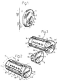
- Figure 1 illustrates a cylinder lock 1 and a surrounding fitting 2 mounted in place in a door 3.
- the lock cylinder 4 of the cylinder lock 1 has a bore which receives a plug 7 of the kind shown in Figure 2, said plug 7 being rotatable in the lock-cylinder bore by means of a key (not shown).
- the front part 7b of the plug 7 has a larger diameter than the main part 7a of the plug and is received in an enlarged front part of the bore in the lock cylinder 4.
- the enlarged front part 7b of the plug includes a key-slot or key-hole 8 which merges with a slot 9 in the main plug-part 7a.
- the key slot 8 has a comparatively regular profile, whereas the slot 9 may have an irregular shape so that only a given number of keys belonging to the same key-family can be inserted into the plug for actuation of the pin tumblers 13 accommodated in the pin channel 12 therein.
- pin channels 12 Only one row of pin channels 12 is shown in the drawing. Each of these pin channels 12 accommodates a pin tumbler 13 adapted for co-action with a latch rod or latch bar 15 accommodated in a recess 14 in the plug 7.
- the plug may include in addition to these pin channels or instead of said pin channels a central row of pin channels (not visible in Figures 2 and 3) that accommodate bottom pins which co-act typically with top pins (not shown) in the lock cylinder 4, optionally via intermediate pins (not shown either).
- a profiled element 5 Attached in front of the enlarged front-plug part 7b is a profiled element 5 which is made of a hard material, e.g. stainless steel, and which has a front surface 5a.
- the profiled element 5 includes a key hole 6 whose profiled shape differs somewhat from the profiled shape of the key-slot 9 provided in the main plug-part 7a, such that only one or a few individuals of the key-family that can be inserted into the plug 7 will also fit the key hole 6 of the profiled element 5.
- the profiled element 5 In order to enable the profiled element 5 to be fitted securely in the main plug-part 7a so as to deny access to the profiled element from outside, the profiled element is provided with attachment elements 5b which, in the illustrated embodiment - cf Figure 5 for instance - have a general U-shape with one leg of the U on each side of the key hole 6, said legs being interconnected by an intermediate part which is taken around one end of the key hole 6.
- engagement surfaces 5b' of these attachment or anchoring elements 5b thus extend beyond one end of the key hole 6 and the key slot 8, 9, respectively, without reaching to the peripheral surface of the plug located radially outside the end of the key slot.
- the attachment or anchoring elements 5b co-act with corresponding attachment elements 7c in the enlarged part 7b of the plug 7, more specifically so that the engagement surfaces 5b' on the profiled-element attachment elements 5b co-act with corresponding engagement surfaces 7c' on the attachment elements 7c in the enlarged plug-part 7b.
- the profiled element 5 will be held securely and reliably on the plug 7, more specifically so that both the profiled element 5 and the plug will be inaccessible to an external attack, e.g. with a screwdriver, chisel or drill.
- the lock cylinder 4 therewith contributes towards secure anchorage of the profiled element 5, since the lock cylinder ensures that no part of the anchoring elements 5b, 7c and their associated engagement surfaces 5b', 7c' are accessible from outside the lock.
- the profiled element can be removed from the plug very easily. All that is necessary in this respect is to partially withdraw the plug from the bore in the lock cylinder 4, so as to enable the profiled element to be removed in a direction perpendicular to the direction of the plug axis (cf. Fig. 3), when exchanging the profiled element for another profiled element for instance.
- the profiled element is fitted in a corresponding manner, in the opposite direction, i.e. in a direction perpendicular to the plug axis.
- the front plug-part 7'b with the front surface 7'b" has the same diameter as the remainder of the plug; in other words the part of the plug provided with the engagement surfaces 7'c is not enlarged in relation to the main part of the plug.
- the key hole 6' in the profiled element 5' is completely surrounded by material, i.e. even in the region of the engagement surfaces 5'b' on the profiled element.
- the profiled element 5' thus has greater resistance to an attack from outside the lock.
- a profiled element 5' whose key hole 6' is totally delimited by material may be accommodated in a front, enlarged plug-part or, alternatively, a slot-like key hole in the profiled element, e.g. according to Figures 4 and 5, may be accommodated in a plug that lacks an enlarged front part.
- the attachment or anchoring elements 5b, 5b' of the profiled element may be designed in a manner different to that illustrated in the associated figures, provided that reliable and secure anchoring of the profiled element to the plug can be achieved and provided that the design of said elements falls within the scope of the following claims.
Landscapes
- Lock And Its Accessories (AREA)
- Details Of Connecting Devices For Male And Female Coupling (AREA)
- Connector Housings Or Holding Contact Members (AREA)
- Pens And Brushes (AREA)
- Insertion Pins And Rivets (AREA)
- Fluid-Damping Devices (AREA)
- Component Parts Of Construction Machinery (AREA)
- Springs (AREA)
- Saccharide Compounds (AREA)
- Pharmaceuticals Containing Other Organic And Inorganic Compounds (AREA)
- Vehicle Body Suspensions (AREA)
- Chairs Characterized By Structure (AREA)
- Valve Device For Special Equipments (AREA)
- Actuator (AREA)
Abstract
Description
Claims (8)
- A cylinder lock comprisingcharacterized in that the outer surface (5a) of the profiled element (5) which consists of a hard material, for instance stainless steel, in the applied position of the element forms the complete outer surface of the core, and in that said cooperating engagement surfaces (5b'; 7c') of the attachment or anchoring members are situated at an axial distance from the profiled element's rear side which lies close to the core's outer end surface (7b').a) a lock cylinder (4) having a bore forb) rotatably accommodating a plug (7);c) a key slot (8, 9) in the plug for insertion of a key blade having a profile adapted to the profile of the slot;d) at least one row of pin channels (12) in the plug for accommodating pin tumblers (13) co-acting with the key blade;e) a profiled element (5; 5') mounted at the front end of the plug (7) and provided with a key hole (6; 6') having a profile which deviates partially from the profile of the plug key-slot, so that only certain keys that are insertable into the plug key-slot can be inserted into the key hole (6) of the profiled element (5); andf) members or elements (5b; 7c) for releasably attaching the profiled element to the plug (7), said members being inaccessible from outside the lock when the plug is inserted to its use position in said bore, said attachment members having an engagement surface (5b') which extends perpendicular to the plug axis and which is located closer to the front end of the plug than the first pin channel (12) in said row, and which engagement surface (5b') is adapted for co-action with a corresponding engagement surface (7c') on said plug such as to anchor the profiled element (5) reliably to the plug (7);g) said engagement surfaces (5b'; 7c') of the attachment or anchoring members extending beyond at least one end of the key hole (6) and the key slot (8, 9), respectively, without reaching the peripheral surface of the plug located radially outside said end of said key slot, and enabling the profiled element (5) to be fitted or applied perpendicularly to the plug axis when the plug is at least partially removed from the bore in the lock cylinder (4),
- A cylinder lock according to Claim 1, characterized in that the length of the engagement surfaces (5b'; 7c') parallel with the direction of the key slot (6) is greater than the plug radius and smaller than the plug diameter.
- A cylinder lock according to Claim 1 or Claim 2, in which the profiled element (5) and the plug (7) include mutually co-acting engagement surfaces (5b'; 7c') on each side of the key hole (6) in the profiled element (5) and the key slot (9) in the plug (7) respectively, characterized in that the attachment element (5b) on the engagement surface or surfaces (5b') of the profiled element has a generally U-shape, where the engagement surface (5b') extends continuously on one side of the key hole (6) and around said one end thereof.
- A cylinder lock according to Claim 3, characterized in that the engagement surface (7c') on the plug (7) has a corresponding U-shape on one side of the plug key-slot (8, 9) and around said one end thereof.
- A cylinder lock according to Claim 1 or Claim 2, characterized in that the key hole (6') in the profiled element is completely delimited by material, preferably also in the region of said engagement surface (5'b'). (Figs. 6 and 7).
- A cylinder lock according to Claim 1, characterized in that the plug-part provided with said engagement surface or surfaces (7c') is located in the front end of a plug-part (7b) that has a larger diameter than the main plug-part (7a).
- A cylinder lock according to Claim 6, characterized in that the diameter of the profiled element (5) corresponds to the diameter of said enlarged plug-part (7b).
- A cylinder lock according to Claim 7, characterized in that the plug-part (7b) of larger diameter is accommodated in an enlarged front part of the bore in the lock cylinder (4) in which the plug (7) is accommodated, wherein the axial length of said enlarged part of the bore corresponds to the combined thickness of the profiled element (5) and the enlarged plug-part (7b).
Applications Claiming Priority (3)
| Application Number | Priority Date | Filing Date | Title |
|---|---|---|---|
| SE9603981 | 1996-10-31 | ||
| SE9603981A SE510984C2 (en) | 1996-10-31 | 1996-10-31 | Cylinder |
| PCT/SE1997/001820 WO1998019031A1 (en) | 1996-10-31 | 1997-10-30 | A cylinder lock |
Publications (2)
| Publication Number | Publication Date |
|---|---|
| EP0948690A1 EP0948690A1 (en) | 1999-10-13 |
| EP0948690B1 true EP0948690B1 (en) | 2003-03-05 |
Family
ID=20404441
Family Applications (1)
| Application Number | Title | Priority Date | Filing Date |
|---|---|---|---|
| EP97911566A Expired - Lifetime EP0948690B1 (en) | 1996-10-31 | 1997-10-30 | A cylinder lock |
Country Status (9)
| Country | Link |
|---|---|
| US (1) | US6155090A (en) |
| EP (1) | EP0948690B1 (en) |
| AT (1) | ATE233850T1 (en) |
| CA (1) | CA2269830C (en) |
| DE (1) | DE69719554T2 (en) |
| DK (1) | DK0948690T3 (en) |
| NO (1) | NO992121D0 (en) |
| SE (1) | SE510984C2 (en) |
| WO (1) | WO1998019031A1 (en) |
Cited By (3)
| Publication number | Priority date | Publication date | Assignee | Title |
|---|---|---|---|---|
| DE102017115417A1 (en) | 2017-07-10 | 2019-01-10 | C. Ed. Schulte Gmbh Zylinderschlossfabrik | Lock core, lock cylinder, key, locking device and cylinder lock and method for this purpose |
| DE102017115415A1 (en) | 2017-07-10 | 2019-01-10 | C. Ed. Schulte Gmbh Zylinderschlossfabrik | Lock core, lock cylinder, key, locking device and cylinder lock and method for this purpose |
| CH718767A1 (en) * | 2021-06-25 | 2022-12-30 | Sea Schliess Systeme Ag | Cylinder lock with a front plate. |
Families Citing this family (50)
| Publication number | Priority date | Publication date | Assignee | Title |
|---|---|---|---|---|
| DE19815212A1 (en) * | 1998-04-04 | 1999-10-21 | Schlossicherungen Gera Gmbh | Flat key for cylinder lock, with longitudinal grooves and or ridges |
| US6079240A (en) * | 1998-07-24 | 2000-06-27 | Arrow Lock Manufacturing Company | Modular removable core cylinder assembly |
| GB9927853D0 (en) * | 1999-11-26 | 2000-01-26 | Kibble Anthony W | Lock cylinder and plug therefor |
| FR2802231B1 (en) * | 1999-12-10 | 2002-07-05 | Bricard Sa | UNIVERSAL ANTI-DRILLING PAD FOR LOCK CYLINDER |
| US6939434B2 (en) | 2000-08-11 | 2005-09-06 | Applied Materials, Inc. | Externally excited torroidal plasma source with magnetic control of ion distribution |
| US7294563B2 (en) | 2000-08-10 | 2007-11-13 | Applied Materials, Inc. | Semiconductor on insulator vertical transistor fabrication and doping process |
| US6893907B2 (en) | 2002-06-05 | 2005-05-17 | Applied Materials, Inc. | Fabrication of silicon-on-insulator structure using plasma immersion ion implantation |
| US7223676B2 (en) | 2002-06-05 | 2007-05-29 | Applied Materials, Inc. | Very low temperature CVD process with independently variable conformality, stress and composition of the CVD layer |
| US7166524B2 (en) | 2000-08-11 | 2007-01-23 | Applied Materials, Inc. | Method for ion implanting insulator material to reduce dielectric constant |
| US7137354B2 (en) | 2000-08-11 | 2006-11-21 | Applied Materials, Inc. | Plasma immersion ion implantation apparatus including a plasma source having low dissociation and low minimum plasma voltage |
| US7094670B2 (en) | 2000-08-11 | 2006-08-22 | Applied Materials, Inc. | Plasma immersion ion implantation process |
| US7479456B2 (en) | 2004-08-26 | 2009-01-20 | Applied Materials, Inc. | Gasless high voltage high contact force wafer contact-cooling electrostatic chuck |
| US7037813B2 (en) | 2000-08-11 | 2006-05-02 | Applied Materials, Inc. | Plasma immersion ion implantation process using a capacitively coupled plasma source having low dissociation and low minimum plasma voltage |
| US7465478B2 (en) | 2000-08-11 | 2008-12-16 | Applied Materials, Inc. | Plasma immersion ion implantation process |
| US7183177B2 (en) | 2000-08-11 | 2007-02-27 | Applied Materials, Inc. | Silicon-on-insulator wafer transfer method using surface activation plasma immersion ion implantation for wafer-to-wafer adhesion enhancement |
| US7320734B2 (en) | 2000-08-11 | 2008-01-22 | Applied Materials, Inc. | Plasma immersion ion implantation system including a plasma source having low dissociation and low minimum plasma voltage |
| US7288491B2 (en) | 2000-08-11 | 2007-10-30 | Applied Materials, Inc. | Plasma immersion ion implantation process |
| US7430984B2 (en) | 2000-08-11 | 2008-10-07 | Applied Materials, Inc. | Method to drive spatially separate resonant structure with spatially distinct plasma secondaries using a single generator and switching elements |
| US7303982B2 (en) | 2000-08-11 | 2007-12-04 | Applied Materials, Inc. | Plasma immersion ion implantation process using an inductively coupled plasma source having low dissociation and low minimum plasma voltage |
| FI120010B (en) * | 2003-03-11 | 2009-05-29 | Abloy Oy | Låskistarrangemang |
| WO2004111369A1 (en) | 2003-06-16 | 2004-12-23 | Camware Holdings Pty Ltd | Rotary lock and key |
| US7291360B2 (en) | 2004-03-26 | 2007-11-06 | Applied Materials, Inc. | Chemical vapor deposition plasma process using plural ion shower grids |
| US7244474B2 (en) | 2004-03-26 | 2007-07-17 | Applied Materials, Inc. | Chemical vapor deposition plasma process using an ion shower grid |
| US7695590B2 (en) | 2004-03-26 | 2010-04-13 | Applied Materials, Inc. | Chemical vapor deposition plasma reactor having plural ion shower grids |
| US20050217329A1 (en) * | 2004-04-02 | 2005-10-06 | Wen-Kwei Chang | Anti-drilling structure of a latch |
| US8058156B2 (en) | 2004-07-20 | 2011-11-15 | Applied Materials, Inc. | Plasma immersion ion implantation reactor having multiple ion shower grids |
| US7767561B2 (en) | 2004-07-20 | 2010-08-03 | Applied Materials, Inc. | Plasma immersion ion implantation reactor having an ion shower grid |
| US7666464B2 (en) | 2004-10-23 | 2010-02-23 | Applied Materials, Inc. | RF measurement feedback control and diagnostics for a plasma immersion ion implantation reactor |
| US7796116B2 (en) | 2005-01-12 | 2010-09-14 | Thinkoptics, Inc. | Electronic equipment for handheld vision based absolute pointing system |
| US7428915B2 (en) | 2005-04-26 | 2008-09-30 | Applied Materials, Inc. | O-ringless tandem throttle valve for a plasma reactor chamber |
| US7312162B2 (en) | 2005-05-17 | 2007-12-25 | Applied Materials, Inc. | Low temperature plasma deposition process for carbon layer deposition |
| US7422775B2 (en) | 2005-05-17 | 2008-09-09 | Applied Materials, Inc. | Process for low temperature plasma deposition of an optical absorption layer and high speed optical annealing |
| US7109098B1 (en) | 2005-05-17 | 2006-09-19 | Applied Materials, Inc. | Semiconductor junction formation process including low temperature plasma deposition of an optical absorption layer and high speed optical annealing |
| US7429532B2 (en) | 2005-08-08 | 2008-09-30 | Applied Materials, Inc. | Semiconductor substrate process using an optically writable carbon-containing mask |
| US7323401B2 (en) | 2005-08-08 | 2008-01-29 | Applied Materials, Inc. | Semiconductor substrate process using a low temperature deposited carbon-containing hard mask |
| US7312148B2 (en) | 2005-08-08 | 2007-12-25 | Applied Materials, Inc. | Copper barrier reflow process employing high speed optical annealing |
| US7335611B2 (en) | 2005-08-08 | 2008-02-26 | Applied Materials, Inc. | Copper conductor annealing process employing high speed optical annealing with a low temperature-deposited optical absorber layer |
| WO2008014536A1 (en) * | 2006-08-03 | 2008-02-07 | Watts Hardware Manufacturing Pty Ltd | Improvements in members & ironmongery |
| US9273487B2 (en) * | 2006-12-21 | 2016-03-01 | United States Postal Service | High-strength lock, method of making high-strength lock, and method for mounting high-strength lock |
| US20080196460A1 (en) * | 2006-12-29 | 2008-08-21 | Kevin Houlihan | Insertable lock plug |
| DE102007007688A1 (en) * | 2007-02-16 | 2008-08-21 | C. Ed. Schulte Gmbh Zylinderschlossfabrik | Lock cylinder with wear protection |
| US20100024497A1 (en) * | 2008-08-04 | 2010-02-04 | Kun-Yu Wu | Lock assembly with picking resistant shield |
| US7770422B1 (en) | 2008-11-03 | 2010-08-10 | Rafael Sierra | Round padlock |
| IT1396304B1 (en) * | 2009-11-06 | 2012-11-16 | Dierre Spa | LOCK OF THE TYPE A MAP |
| DE102014108922A1 (en) * | 2014-06-25 | 2015-12-31 | Huf Hülsbeck & Fürst Gmbh & Co. Kg | Locking cylinder system |
| EP2990569B1 (en) * | 2014-08-26 | 2017-09-20 | dormakaba Deutschland GmbH | Cylinder core for a cylinder for locks |
| US9222283B1 (en) * | 2015-03-19 | 2015-12-29 | Digilock Asia Ltd. | Combination lock with override key |
| EP3095931B1 (en) * | 2015-05-22 | 2019-10-09 | BKS GmbH | Lock cylinder and lock system with such a lock cylinder |
| EP3219882B1 (en) * | 2016-03-16 | 2018-07-11 | Assa Ab | Cylinder lock and key system |
| GB2578865B (en) * | 2018-10-01 | 2022-06-15 | Inkster David | Improvements in or relating to security |
Family Cites Families (11)
| Publication number | Priority date | Publication date | Assignee | Title |
|---|---|---|---|---|
| US1422517A (en) * | 1921-09-02 | 1922-07-11 | Yale & Towne Mfg Co | Pin-tumbler lock |
| US1422594A (en) * | 1921-09-02 | 1922-07-11 | Yale & Towne Mfg Co | Pin-tumbler lock |
| US1411898A (en) * | 1921-09-02 | 1922-04-04 | Yale & Towne Mfg Co | Pin-tumbler lock |
| US1568462A (en) * | 1924-03-27 | 1926-01-05 | Frank E Best Inc | Faceplate-attaching means for locks |
| US1575092A (en) * | 1924-10-09 | 1926-03-02 | Frank E Best Inc | Lock face |
| US3736780A (en) * | 1971-04-28 | 1973-06-05 | M Singer | Device for altering lock cylinder to receive a new key |
| US4498327A (en) * | 1981-03-30 | 1985-02-12 | Taboola Pty. Ltd. | Cylinder locks and keys therefor |
| US5383344A (en) * | 1993-06-01 | 1995-01-24 | Zambell; Robert G. | Steering wheel lock assembly |
| US5507163A (en) * | 1994-04-04 | 1996-04-16 | Juang; Wen-Jang | Interchangeable lock core structure |
| US5737948A (en) * | 1996-12-17 | 1998-04-14 | Lefkovits; Jacob | Access control system |
| US6079240A (en) * | 1998-07-24 | 2000-06-27 | Arrow Lock Manufacturing Company | Modular removable core cylinder assembly |
-
1996
- 1996-10-31 SE SE9603981A patent/SE510984C2/en not_active IP Right Cessation
-
1997
- 1997-10-30 US US09/284,868 patent/US6155090A/en not_active Expired - Lifetime
- 1997-10-30 EP EP97911566A patent/EP0948690B1/en not_active Expired - Lifetime
- 1997-10-30 CA CA002269830A patent/CA2269830C/en not_active Expired - Fee Related
- 1997-10-30 DK DK97911566T patent/DK0948690T3/en active
- 1997-10-30 AT AT97911566T patent/ATE233850T1/en not_active IP Right Cessation
- 1997-10-30 DE DE69719554T patent/DE69719554T2/en not_active Expired - Lifetime
- 1997-10-30 WO PCT/SE1997/001820 patent/WO1998019031A1/en not_active Ceased
-
1999
- 1999-04-30 NO NO992121A patent/NO992121D0/en not_active Application Discontinuation
Cited By (3)
| Publication number | Priority date | Publication date | Assignee | Title |
|---|---|---|---|---|
| DE102017115417A1 (en) | 2017-07-10 | 2019-01-10 | C. Ed. Schulte Gmbh Zylinderschlossfabrik | Lock core, lock cylinder, key, locking device and cylinder lock and method for this purpose |
| DE102017115415A1 (en) | 2017-07-10 | 2019-01-10 | C. Ed. Schulte Gmbh Zylinderschlossfabrik | Lock core, lock cylinder, key, locking device and cylinder lock and method for this purpose |
| CH718767A1 (en) * | 2021-06-25 | 2022-12-30 | Sea Schliess Systeme Ag | Cylinder lock with a front plate. |
Also Published As
| Publication number | Publication date |
|---|---|
| SE510984C2 (en) | 1999-07-19 |
| US6155090A (en) | 2000-12-05 |
| NO992121L (en) | 1999-04-30 |
| WO1998019031A1 (en) | 1998-05-07 |
| DK0948690T3 (en) | 2003-06-02 |
| SE9603981D0 (en) | 1996-10-31 |
| SE9603981L (en) | 1998-05-01 |
| EP0948690A1 (en) | 1999-10-13 |
| ATE233850T1 (en) | 2003-03-15 |
| HK1025140A1 (en) | 2000-11-03 |
| DE69719554D1 (en) | 2003-04-10 |
| NO992121D0 (en) | 1999-04-30 |
| CA2269830A1 (en) | 1998-05-07 |
| DE69719554T2 (en) | 2004-02-19 |
| CA2269830C (en) | 2006-05-09 |
Similar Documents
| Publication | Publication Date | Title |
|---|---|---|
| US6155090A (en) | Cylinder lock | |
| US5572890A (en) | High security lock system including cover plate | |
| US5615566A (en) | Cylinder lock and key | |
| US5088306A (en) | Cylinder lock with changeable keyway | |
| WO2007122609A1 (en) | Padlock hasp assembly | |
| US4576025A (en) | Magnetic lock insert for lock mechanisms | |
| ATE342414T1 (en) | LOCK CYLINDER WITH KEY | |
| IL155823A (en) | Cylinder lock with adjustable length | |
| US20060230797A1 (en) | Key core | |
| US11255107B2 (en) | Key encasement having a combination lock | |
| EP2314805B1 (en) | Device for protecting locks | |
| HK1025140B (en) | A cylinder lock | |
| ITBS20110086A1 (en) | LOCK CYLINDER | |
| ATE384838T1 (en) | CYLINDER LOCK KEY COMBINATION | |
| EP0953703B1 (en) | Shackleless security padlock | |
| EP2865825A1 (en) | Cylinder lock arrangement | |
| ATE160200T1 (en) | ROTARY LOCKING CYLINDER FOR A SECURITY LOCK | |
| JP3042294U (en) | Cylinder lock | |
| EP2865827B1 (en) | Cylinder lock arrangement | |
| JP3142446B2 (en) | Cylinder lock | |
| CA1273216A (en) | High security lock | |
| WO2001038674A1 (en) | Lock cylinder, plug therefor, and method of manufacturing | |
| JPH10306633A (en) | Double pin tumbler type locking device | |
| EP1449989A1 (en) | Locks | |
| NZ328154A (en) | Cylinder lock-key combination with groove(s) in cylinder housing coacting with key spine profile to prevent turning of key with wrong profile |
Legal Events
| Date | Code | Title | Description |
|---|---|---|---|
| PUAI | Public reference made under article 153(3) epc to a published international application that has entered the european phase |
Free format text: ORIGINAL CODE: 0009012 |
|
| 17P | Request for examination filed |
Effective date: 19990503 |
|
| AK | Designated contracting states |
Kind code of ref document: A1 Designated state(s): AT BE CH DE DK ES FI FR GB GR IE IT LI LU MC NL PT SE |
|
| AX | Request for extension of the european patent |
Free format text: LT PAYMENT 19990503;LV PAYMENT 19990503;RO PAYMENT 19990503 |
|
| 17Q | First examination report despatched |
Effective date: 20011009 |
|
| GRAG | Despatch of communication of intention to grant |
Free format text: ORIGINAL CODE: EPIDOS AGRA |
|
| GRAG | Despatch of communication of intention to grant |
Free format text: ORIGINAL CODE: EPIDOS AGRA |
|
| GRAH | Despatch of communication of intention to grant a patent |
Free format text: ORIGINAL CODE: EPIDOS IGRA |
|
| GRAH | Despatch of communication of intention to grant a patent |
Free format text: ORIGINAL CODE: EPIDOS IGRA |
|
| GRAA | (expected) grant |
Free format text: ORIGINAL CODE: 0009210 |
|
| AK | Designated contracting states |
Designated state(s): AT BE CH DE DK ES FI FR GB GR IE IT LI LU MC NL PT SE |
|
| AX | Request for extension of the european patent |
Extension state: LT LV RO |
|
| PG25 | Lapsed in a contracting state [announced via postgrant information from national office to epo] |
Ref country code: NL Free format text: LAPSE BECAUSE OF FAILURE TO SUBMIT A TRANSLATION OF THE DESCRIPTION OR TO PAY THE FEE WITHIN THE PRESCRIBED TIME-LIMIT Effective date: 20030305 Ref country code: LI Free format text: LAPSE BECAUSE OF FAILURE TO SUBMIT A TRANSLATION OF THE DESCRIPTION OR TO PAY THE FEE WITHIN THE PRESCRIBED TIME-LIMIT Effective date: 20030305 Ref country code: IT Free format text: LAPSE BECAUSE OF FAILURE TO SUBMIT A TRANSLATION OF THE DESCRIPTION OR TO PAY THE FEE WITHIN THE PRESCRIBED TIME-LIMIT;WARNING: LAPSES OF ITALIAN PATENTS WITH EFFECTIVE DATE BEFORE 2007 MAY HAVE OCCURRED AT ANY TIME BEFORE 2007. THE CORRECT EFFECTIVE DATE MAY BE DIFFERENT FROM THE ONE RECORDED. Effective date: 20030305 Ref country code: GR Free format text: LAPSE BECAUSE OF FAILURE TO SUBMIT A TRANSLATION OF THE DESCRIPTION OR TO PAY THE FEE WITHIN THE PRESCRIBED TIME-LIMIT Effective date: 20030305 Ref country code: FI Free format text: LAPSE BECAUSE OF FAILURE TO SUBMIT A TRANSLATION OF THE DESCRIPTION OR TO PAY THE FEE WITHIN THE PRESCRIBED TIME-LIMIT Effective date: 20030305 Ref country code: CH Free format text: LAPSE BECAUSE OF FAILURE TO SUBMIT A TRANSLATION OF THE DESCRIPTION OR TO PAY THE FEE WITHIN THE PRESCRIBED TIME-LIMIT Effective date: 20030305 Ref country code: BE Free format text: LAPSE BECAUSE OF FAILURE TO SUBMIT A TRANSLATION OF THE DESCRIPTION OR TO PAY THE FEE WITHIN THE PRESCRIBED TIME-LIMIT Effective date: 20030305 Ref country code: AT Free format text: LAPSE BECAUSE OF FAILURE TO SUBMIT A TRANSLATION OF THE DESCRIPTION OR TO PAY THE FEE WITHIN THE PRESCRIBED TIME-LIMIT Effective date: 20030305 |
|
| REG | Reference to a national code |
Ref country code: GB Ref legal event code: FG4D |
|
| REG | Reference to a national code |
Ref country code: CH Ref legal event code: EP |
|
| REG | Reference to a national code |
Ref country code: IE Ref legal event code: FG4D |
|
| REF | Corresponds to: |
Ref document number: 69719554 Country of ref document: DE Date of ref document: 20030410 Kind code of ref document: P |
|
| REG | Reference to a national code |
Ref country code: DK Ref legal event code: T3 |
|
| PG25 | Lapsed in a contracting state [announced via postgrant information from national office to epo] |
Ref country code: SE Free format text: LAPSE BECAUSE OF FAILURE TO SUBMIT A TRANSLATION OF THE DESCRIPTION OR TO PAY THE FEE WITHIN THE PRESCRIBED TIME-LIMIT Effective date: 20030605 Ref country code: PT Free format text: LAPSE BECAUSE OF FAILURE TO SUBMIT A TRANSLATION OF THE DESCRIPTION OR TO PAY THE FEE WITHIN THE PRESCRIBED TIME-LIMIT Effective date: 20030605 |
|
| NLV1 | Nl: lapsed or annulled due to failure to fulfill the requirements of art. 29p and 29m of the patents act | ||
| REG | Reference to a national code |
Ref country code: CH Ref legal event code: PL |
|
| PG25 | Lapsed in a contracting state [announced via postgrant information from national office to epo] |
Ref country code: ES Free format text: LAPSE BECAUSE OF FAILURE TO SUBMIT A TRANSLATION OF THE DESCRIPTION OR TO PAY THE FEE WITHIN THE PRESCRIBED TIME-LIMIT Effective date: 20030930 |
|
| PG25 | Lapsed in a contracting state [announced via postgrant information from national office to epo] |
Ref country code: LU Free format text: LAPSE BECAUSE OF NON-PAYMENT OF DUE FEES Effective date: 20031030 Ref country code: IE Free format text: LAPSE BECAUSE OF NON-PAYMENT OF DUE FEES Effective date: 20031030 |
|
| PG25 | Lapsed in a contracting state [announced via postgrant information from national office to epo] |
Ref country code: MC Free format text: LAPSE BECAUSE OF NON-PAYMENT OF DUE FEES Effective date: 20031031 |
|
| ET | Fr: translation filed | ||
| PLBE | No opposition filed within time limit |
Free format text: ORIGINAL CODE: 0009261 |
|
| STAA | Information on the status of an ep patent application or granted ep patent |
Free format text: STATUS: NO OPPOSITION FILED WITHIN TIME LIMIT |
|
| 26N | No opposition filed |
Effective date: 20031208 |
|
| REG | Reference to a national code |
Ref country code: IE Ref legal event code: MM4A |
|
| PGFP | Annual fee paid to national office [announced via postgrant information from national office to epo] |
Ref country code: DK Payment date: 20131010 Year of fee payment: 17 |
|
| PGFP | Annual fee paid to national office [announced via postgrant information from national office to epo] |
Ref country code: FR Payment date: 20131009 Year of fee payment: 17 Ref country code: GB Payment date: 20131030 Year of fee payment: 17 Ref country code: DE Payment date: 20131023 Year of fee payment: 17 |
|
| REG | Reference to a national code |
Ref country code: DE Ref legal event code: R119 Ref document number: 69719554 Country of ref document: DE |
|
| GBPC | Gb: european patent ceased through non-payment of renewal fee |
Effective date: 20141030 |
|
| REG | Reference to a national code |
Ref country code: LT Ref legal event code: MM9D Effective date: 20141030 |
|
| PG25 | Lapsed in a contracting state [announced via postgrant information from national office to epo] |
Ref country code: DE Free format text: LAPSE BECAUSE OF NON-PAYMENT OF DUE FEES Effective date: 20150501 Ref country code: GB Free format text: LAPSE BECAUSE OF NON-PAYMENT OF DUE FEES Effective date: 20141030 |
|
| REG | Reference to a national code |
Ref country code: FR Ref legal event code: ST Effective date: 20150630 |
|
| REG | Reference to a national code |
Ref country code: DK Ref legal event code: EBP Effective date: 20141031 |
|
| PG25 | Lapsed in a contracting state [announced via postgrant information from national office to epo] |
Ref country code: FR Free format text: LAPSE BECAUSE OF NON-PAYMENT OF DUE FEES Effective date: 20141031 |
|
| PG25 | Lapsed in a contracting state [announced via postgrant information from national office to epo] |
Ref country code: DK Free format text: LAPSE BECAUSE OF NON-PAYMENT OF DUE FEES Effective date: 20141031 |