EP0948582B1 - Hydrocarbon conversion process - Google Patents
Hydrocarbon conversion process Download PDFInfo
- Publication number
- EP0948582B1 EP0948582B1 EP97937280A EP97937280A EP0948582B1 EP 0948582 B1 EP0948582 B1 EP 0948582B1 EP 97937280 A EP97937280 A EP 97937280A EP 97937280 A EP97937280 A EP 97937280A EP 0948582 B1 EP0948582 B1 EP 0948582B1
- Authority
- EP
- European Patent Office
- Prior art keywords
- hydrotreating
- steam
- catalyst
- zone
- group
- Prior art date
- Legal status (The legal status is an assumption and is not a legal conclusion. Google has not performed a legal analysis and makes no representation as to the accuracy of the status listed.)
- Expired - Lifetime
Links
Images

Classifications
-
- C—CHEMISTRY; METALLURGY
- C10—PETROLEUM, GAS OR COKE INDUSTRIES; TECHNICAL GASES CONTAINING CARBON MONOXIDE; FUELS; LUBRICANTS; PEAT
- C10G—CRACKING HYDROCARBON OILS; PRODUCTION OF LIQUID HYDROCARBON MIXTURES, e.g. BY DESTRUCTIVE HYDROGENATION, OLIGOMERISATION, POLYMERISATION; RECOVERY OF HYDROCARBON OILS FROM OIL-SHALE, OIL-SAND, OR GASES; REFINING MIXTURES MAINLY CONSISTING OF HYDROCARBONS; REFORMING OF NAPHTHA; MINERAL WAXES
- C10G69/00—Treatment of hydrocarbon oils by at least one hydrotreatment process and at least one other conversion process
- C10G69/02—Treatment of hydrocarbon oils by at least one hydrotreatment process and at least one other conversion process plural serial stages only
- C10G69/06—Treatment of hydrocarbon oils by at least one hydrotreatment process and at least one other conversion process plural serial stages only including at least one step of thermal cracking in the absence of hydrogen
-
- C—CHEMISTRY; METALLURGY
- C10—PETROLEUM, GAS OR COKE INDUSTRIES; TECHNICAL GASES CONTAINING CARBON MONOXIDE; FUELS; LUBRICANTS; PEAT
- C10G—CRACKING HYDROCARBON OILS; PRODUCTION OF LIQUID HYDROCARBON MIXTURES, e.g. BY DESTRUCTIVE HYDROGENATION, OLIGOMERISATION, POLYMERISATION; RECOVERY OF HYDROCARBON OILS FROM OIL-SHALE, OIL-SAND, OR GASES; REFINING MIXTURES MAINLY CONSISTING OF HYDROCARBONS; REFORMING OF NAPHTHA; MINERAL WAXES
- C10G65/00—Treatment of hydrocarbon oils by two or more hydrotreatment processes only
- C10G65/02—Treatment of hydrocarbon oils by two or more hydrotreatment processes only plural serial stages only
- C10G65/04—Treatment of hydrocarbon oils by two or more hydrotreatment processes only plural serial stages only including only refining steps
- C10G65/08—Treatment of hydrocarbon oils by two or more hydrotreatment processes only plural serial stages only including only refining steps at least one step being a hydrogenation of the aromatic hydrocarbons
Definitions
- This invention relates to a process for upgrading hydrocarbon feedstocks for subsequent use in steam cracking.
- this invention describes a process for upgrading hydrocarbon feedstocks for use in steam cracking by the application of successive hydrotreating and hydrogenation of the unsaturated and/or aromatic species found therein, and the resultant yield increase of hydrogen, C 1 -C 4 hydrocarbons and steam cracked naphtha, and the concomitant decrease in the yield of steam cracked gas oil and steam cracked tar, upon steam cracking of the hydrotreated and hydrogenated hydrocarbon feedstocks.
- Steam cracking is a process widely known in the petrochemical art.
- the primary intent of the process is the production of C 1 -C 4 hydrocarbons, particularly ethylene, propylene, and butadiene, by thermal cracking of hydrocarbon feedstocks in the presence of steam at elevated temperatures.
- the steam cracking process in general has been well described in the publication entitled "Manufacturing Ethylene" by S. B. Zdonik et. al, Oil and Gas Journal Reprints 1966 - 1970.
- Typical liquid feedstocks for conventional steam crackers are straight run (virgin) and hydrotreated straight run (virgin) feedstocks ranging from light naphthas to vacuum gas oils.
- Gaseous feedstocks such as ethane, propane and butane are also commonly processed in the steam cracker.
- the selection of a feedstock for processing in the steam cracker is a function of several criteria including: (i) availability of the feedstock, (ii) cost of the feedstock and (iii) the yield slate derived by steam cracking of that feedstock. Feedstock availability and cost are predominantly a function of global supply and demand issues. On the other hand, the yield slate derived by steam cracking of a given feedstock is a function of the chemical characteristics of that feedstock. In general, the yield of high value C 1 -C 4 hydrocarbons, particularly ethylene, propylene and butadiene, is greatest when the steam cracker feedstocks are gaseous feedstocks such as ethane, propane and butane.
- the yield of the least desirable products of steam cracking, steam cracked gas oil and steam cracked tar are generally even higher when low quality hydrogen deficient cracked feedstocks such as thermally cracked naphtha, thermally cracked gas oil, catalytically cracked naphtha, catalytically cracked gas oil, coker naphthas and coker gas oil are processed.
- low quality hydrogen deficient cracked feedstocks such as thermally cracked naphtha, thermally cracked gas oil, catalytically cracked naphtha, catalytically cracked gas oil, coker naphthas and coker gas oil are processed.
- the significantly increased yield of low value steam cracked gas oil and steam cracked tar products relative to production of high value C 1 -C 4 hydrocarbon products obtained when processing the low quality hydrogen deficient cracked feedstocks is such that these feedstocks are rarely processed in steam crackers.
- Catalytic hydrodesulfurization sulfur removal
- hydrodenitrification nitrogen removal
- hydrogenation olefins, diolefins and aromatics saturation
- Hydrodesulfurization, hydrodenitrification and partial hydrogenation have been applied to upgrading feedstocks for steam cracking as described by Zimmermann in U.S. Patent No. 4,619,757.
- This two stage approach employed base metal, bi-metallic catalysts on both non-acidic (alumina) and acidic (zeolite) supports.
- Winquist et. al. U.S. Patent No. 5,391,291, described an approach for upgrading of kerosene, fuel oil, and vacuum gas oil feedstocks by first pre-treating the feedstock to effect hydrodesulfurization and hydrodenitrification, and thereafter hydrogenation of the resultant liquid hydrocarbon fraction to yield a high cetane number fuel oil product.
- the present invention which comprises successive hydrotreating and hydrogenation steps followed by a steam cracking step results in significant yield improvements for hydrogen, C 1 -C 4 hydrocarbons and steam cracked naphtha when applied to straight run (virgin) feedstocks; and results in high yields of hydrogen, C 1 -C 4 hydrocarbons and steam cracked naphtha and reduced yields of steam cracked gas oil and steam cracked tar when applied to low quality, hydrogen deficient, cracked feedstocks such as thermally cracked naphtha, thermally cracked kerosene, thermally cracked gas oil, catalytically cracked naphtha, catalytically cracked kerosene, catalytically cracked gas oil, coker naphthas, coker kerosene, coker gas oil, steam cracked naphthas and steam cracked gas oils.
- the ability of this process to treat low quality hydrogen deficient cracked feedstocks, such as steam cracked gas oil permits these heretofore undesirable feedstocks to be recycled to extinction through the combined feedstock upgrading and steam cracking
- hydrogen, C 1 -C 4 hydrocarbons and steam cracked naphtha can be produced in higher quantities in a process in which the effluent from at least one hydrotreating zone containing at least one hydrotreating catalyst is passed to an aromatics saturation zone containing an aromatics saturation catalyst, and the effluent from the aromatics saturation zone is then passed to a steam cracking zone.
- the effluents from the steam cracking zone are then passed to one or more fractionating zones in which the effluents are separated into a fraction comprising hydrogen and C 1 -C 4 hydrocarbons, a steam cracked naphtha fraction, a steam cracked gas oil fraction and a steam cracked tar fraction.
- the process of the present invention results in improved yields of the high value steam cracked products, i.e., C 1 -C 4 hydrocarbons, particularly ethylene, propylene, and butadiene, and steam cracked naphtha, particularly isoprene, cis-pentadiene, trans-pentadiene, cyclopentadiene, methylcyclopentadiene, and benzene, and reduced yields of steam cracked gas oil and steam cracked tar.
- the high value steam cracked products i.e., C 1 -C 4 hydrocarbons, particularly ethylene, propylene, and butadiene
- steam cracked naphtha particularly isoprene, cis-pentadiene, trans-pentadiene, cyclopentadiene, methylcyclopentadiene, and benzene
- This invention provides an integrated process for converting a hydrocarbon feedstock having components boiling above 100°C into steam cracked products comprising hydrogen, C 1 -C 4 hydrocarbons, steam cracked naphtha (boiling from C 5 to 220°C), steam cracked gas oil (boiling from 220°C to 275°C) and steam cracked tar (boiling above 275°C).
- the process of the present invention therefore comprises: (i) passing the hydrocarbon feedstock through at least one hydrotreating zone wherein said feedstock is contacted at an elevated temperature and pressure with a hydrogen source and at least one hydrotreating catalyst to effect substantially complete conversion of organic sulfur and/or nitrogen compounds contained therein to H 2 S and NH 3 , respectively; (ii) passing the product from said hydrotreating zone to a product separation zone to remove gases and, if desired, light hydrocarbon fractions; (iii) passing the product from said product separation zone to an aromatics saturation zone wherein said product from said separation zone is contacted at elevated temperature and pressure with a hydrogen source and at least one aromatics saturation catalyst; (iv) passing the product from said aromatics saturation zone to a product separation zone to remove gases and, if desired, light hydrocarbon fractions and thereafter; (v) passing the product from said separation zone to a steam cracking zone and thereafter; (vi) passing the product from said steam cracking zone to one or more product separation zones to separate the product into a fraction comprising hydrogen and C 1
- Figure 1 illustrates one embodiment of the present process wherein a hydrogen containing gas stream is admixed with the hydrocarbon feedstock and passed to one hydrotreating zone employing at least one hydrotreating catalyst.
- the operating conditions of the hydrotreating zone are adjusted to achieve substantially completed desulfurization and denitrification of the hydrocarbon feedstock.
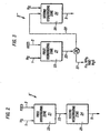
- Figure 2 illustrates a second embodiment of the hydrotreating zone shown in Figure 1 wherein a hydrogen containing gas stream is admixed with the hydrocarbon feedstock and passed, in series flow, to two hydrotreating zones employing two different hydrotreating catalysts contained within two different reactors.
- Figure 3 illustrates a third embodiment of the hydrotreating zone shown in Figure 1 wherein a hydrogen containing gas stream is admixed with the hydrocarbon feedstock and passed to two hydrotreating zones employing two different hydrotreating catalysts contained within two different reactors with an intervening product separation zone.
- C 1 -C 4 hydrocarbons refers to methane, ethane, ethylene, acetylene, propane, propylene, propadiene, methylacetylene, butane, isobutane, isobutylene, butene-1, cis-butene-2, trans-butene-2, butadiene, and C 4 -acetylenes.
- steam cracked naphtha refers to products boiling between C 5 and 220°C, including isoprene, cis-pentadiene, trans-pentadiene, cyclopentadiene, methylcyclopentadiene, and benzene.
- the hydrocarbon feedstock in the process of the present invention typically comprises a hydrocarbon fraction having a major proportion, i.e., greater than 95 percent, of its components boiling above 100°C, preferably above 150°C or higher.
- Suitable feedstocks of this type include straight run (virgin) naphtha, cracked naphthas (e.g. catalytically cracked, steam cracked, and coker naphthas and the like), straight run (virgin) kerosene, cracked kerosenes (e.g. catalytically cracked, steam cracked, and coker kerosenes and the like), straight run (virgin) gas oils (e.g. atmospheric and vacuum gas oil and the like), cracked gas oils (e.g.
- the feedstock will have an extended boiling range, e.g., up to 650°C or higher, but may be of more limited ranges with certain feedstocks. In general, the feedstocks will have a boiling range between 150°C and 650°C.
- the hydrocarbon feedstock and a hydrogen source are contacted with at least one hydrotreating catalyst to effect substantially complete decomposition of organic sulfur and/or nitrogen compounds in the feedstock, i.e., organic sulfur levels below about 100 parts per million, preferably below 50 parts per million, and more preferably below 25 parts per million, and organic nitrogen levels below 15 parts per million, preferably below 5 parts per million, and more preferably below 3 parts per million.
- the source of hydrogen will typically be hydrogen-containing mixtures of gases which normally contain 70 volume percent to 100 volume percent hydrogen.
- the catalyst will typically be one or more conventional hydrotreating catalysts having one or more Group VIB and/or Group VIII (Periodic Table of the Elements) metal compounds supported on an amorphous carrier such as alumina, silica-alumina, silica, zirconia or titania. Examples of such metals comprise nickel, cobalt, molybdenum and tungsten.
- the hydrotreating catalyst is preferably an oxide and/or sulfide of a Group VIII metal, preferably cobalt or nickel, mixed with an oxide and/or a sulfide of a Group VIB metal, preferably molybdenum or tungsten, supported on alumina or silica-alumina.
- the catalysts are preferably in sulfided form.
- the hydrotreating zone contains at least two hydrotreating catalysts in a stacked bed or layered arrangement.
- the first hydrotreating catalyst typically comprises one or more Group VIB and/or Group VIII metal compounds supported on an amorphous carrier such as alumina, silica-alumina, silica, zirconia or titania. Examples of such metals comprise nickel, cobalt, molybdenum and tungsten.
- the first hydrotreating catalyst is preferably an oxide and/or sulfide of a Group VIII metal, preferably cobalt or nickel, mixed with an oxide and/or a sulfide of a Group VIB metal, preferably molybdenum or tungsten, supported on alumina or silica-alumina.
- the second hydrotreating catalyst typically comprises one or more Group VIB and/or Group VIII metal components supported on an acidic porous support. From Group VIB, molybdenum, tungsten and mixtures thereof are preferred. From Group VIII, cobalt, nickel and mixtures thereof are preferred. Preferably, both Group VIB and Group VIII metals are present.
- the hydrotreating component of the second hydrotreating catalyst is nickel and/or cobalt combined with tungsten and/or molybdenum with nickel/tungsten or nickel/molybdenum being particularly preferred.
- the Group VIB and Group VIII metals are supported on an acidic carrier, such as, for example, silica-alumina, or a large pore molecular sieve, i.e. zeolites such as zeolite Y, particularly, ultrastable zeolite Y (zeolite USY), or other dealuminated zeolite Y.
- zeolites such as zeolite Y, particularly, ultrastable zeolite Y (zeolite USY), or other dealuminated zeolite Y.
- Mixtures of the porous amorphous inorganic oxide carriers and the molecular sieves can also be used.
- both the first and second hydrotreating catalysts in the stacked bed arrangement are sulfided prior to use.
- the hydrotreating zone is typically operated at temperatures in the range of from 200°C to 550°C, preferably from 250°C to 500°C, and more preferably from 275°C to 425°C.
- the pressure in the hydrotreating zone is generally in the range of from 400 psig to 3,000 psig (27 bar to 204 bar), preferably from 400 psig to 1,500 psig (27 bar to 102 bar).
- Liquid hourly space velocities will typically be in the range of from 0.1 to 10, preferably from 0.5 to 5 volumes of liquid hydrocarbon per hour per volume of catalyst, and hydrogen to oil ratios will be in the range of from 500 to 10,000 standard cubic feet of hydrogen per barrel of feed (SCF/BBL) (from 0.089 to 2.0 standard cubic meters per liter (m 3 /l)), preferably from 1,000 to 5,000 SCF/BBL (from 0.17 to 0.89 m 3 /l), most preferably from 2,000 to 3,000 SCF/BBL (from 0.35 to 0.53 m 3 /l).
- SCF/BBL standard cubic feet of hydrogen per barrel of feed
- m 3 /l standard cubic meters per liter
- the hydrotreating step may be carried out utilizing two or more hydrotreating zones.
- the hydrotreating step can be carried out in the manner described below in which two zones, a first hydrotreating zone and a second hydrotreating zone, are used.
- the hydrocarbon feedstock and a hydrogen source are contacted with a first hydrotreating catalyst.
- the source of hydrogen will typically be hydrogen-containing mixtures of gases which normally contain 70 volume percent to 100 volume percent hydrogen.
- the first hydrotreating catalyst will typically include one or more Group VIB and/or Group VIII metal compounds on an amorphous carrier such as alumina, silica-alumina, silica, zirconia or titania. Examples of such metals comprise nickel, cobalt, molybdenum and tungsten.
- the first hydrotreating catalyst is preferably an oxide and/or sulfide of a Group VIII metal, preferably cobalt or nickel, mixed with an oxide and/or a sulfide of a Group VIB metal, preferably molybdenum or tungsten, supported on alumina or silica-alumina.
- the catalysts are preferably in sulfided form.
- the first hydrotreating zone is generally operated at temperatures in the range of from 200°C to 550°C, preferably from 250°C to 500°C, and more preferably from 275°C to 425°C.
- the pressure in the first hydrotreating zone is generally in the range of from 400 psig to 3,000 psig (27 bar to 204 bar), preferably from 400 psig to 1,500 psig (27 bar to 102 bar).
- Liquid hourly space velocities will typically be in the range of from 0.2 to 2, preferably from 0.5 to 1 volumes of liquid hydrocarbon per hour per volume of catalyst, and hydrogen to oil ratios will be in the range of from 500 to 10,000 standard cubic feet of hydrogen per barrel of feed (SCP/BBL) (from 0.089 to 2.0 standard cubic meters per liter (m 3 /l)), preferably from 1,000 to 5,000 SCF/BBL (from 0.17 to 0.89 m 3 /l), most preferably from 2,000 to 3,000 SCF/BBL (from 0.35 to 0.53 m 3 /l). These conditions are adjusted to achieve the desired degree of desulfurization and denitrification. Typically, it is desirable in the first hydrotreating zone to reduce the organic sulfur level to below 500 parts per million, preferably below 200 parts per million, and the organic nitrogen level to below 50 parts per million, preferably below 25 parts per million.
- the product from the first hydrotreating zone may then, optionally, be passed to a means whereby ammonia and hydrogen sulfide are removed from the hydrocarbon product by conventional means.
- the hydrocarbon product from the first hydro treating zone is then sent to a second hydrotreating zone.
- the hydrocarbon product may also be passed to a fractionating zone prior to being sent to the second hydrotreating zone if removal of light hydrocarbon fractions is desired.
- the product from the first hydrotreating zone and a hydrogen source typically hydrogen, 70 volume percent to 100 volume percent, in admixture with other gases, are contacted with at least one second hydrotreating catalyst.
- the operating conditions normally used in the second hydrotreating reaction zone include a temperature in the range of from 200°C to 550°C, preferably from 250°C to 500°C, and more preferably, from 275°C to 425°C, a liquid hourly space velocity (LHSV) of 0.1 to 10 volumes of liquid hydrocarbon per hour per volume of catalyst, preferably an LHSV of 0.5 to 5, and a total pressure within the range of 400 psig to 3,000 psig (27 bar to 204 bar), preferably from 400 psig to 1,500 psig (27 bar to 102 bar).
- LHSV liquid hourly space velocity
- the hydrogen circulation rate is generally in the range of from 500 to 10,000 standard cubic feet per barrel (SCF/BBL) (from 0.089 to 2.0 standard cubic meters per liter (m 3 /l)), preferably from 1,000 to 5,000 SCF/BBL (from 0.17 to 0.89 m 3 /l), and more preferably from 2,000 to 3,000 SCF/BBL (from 0.35 to 0.53 m 3 /l). These conditions are adjusted to achieve substantially complete desulfurization and denitrification.
- SCF/BBL standard cubic feet per barrel
- the hydrotreated product obtained from the hydrotreating zone or zones have an organic sulfur level below 100 parts per million, preferably below 50 parts per million, and more preferably below 25 parts per million, and an organic nitrogen level below 15 parts per million, preferably below 5 parts per million and more preferably below 3 parts per million. It is understood that the severity of the operating conditions is decreased as the volume of the feedstock and/or the level of nitrogen and sulfur contaminants to the second hydrotreating zone is decreased. For example, if product gases, including H 2 S and NH 3 (ammonia), and, optionally, light hydrocarbon fractions are removed after the first hydrotreating zone, then the temperature in the second hydrotreating zone will be lower, or alternatively, the LHSV in the second hydrotreating zone will be higher.
- the catalysts typically utilized in the second hydrotreating zone comprise an active metals component supported on an acidic porous support.
- the active metal component, "the hydrotreating component", of the second hydrotreating catalyst is selected from a Group VIB and/or a Group VIII metal component. From Group VIB, molybdenum, tungsten and mixtures thereof are preferred. From Group VIII, cobalt, nickel and mixtures thereof are preferred. Preferably, both Group VIB and Group VIII metals are present.
- the hydrotreating component is nickel and/or cobalt combined with tungsten and/or molybdenum with nickel/tungsten or nickel/molybdenum being particularly preferred.
- the components are typically present in the sulfide form.
- the Group VIB and Group VIII metals are supported on an acidic carrier.
- Two main classes of carriers known in the art are typically utilized: (a) silica-alumina, and (b) the large pore molecular sieves, i.e. zeolites such as Zeolite Y, Mordenite, Zeolite Beta and the like. Mixtures of the porous amorphous inorganic oxide carriers and the molecular sieves are also used.
- sica-alumina refers to non-zeolitic aluminosilicates.
- the most preferred support comprises a zeolite Y, preferably a dealuminated zeolite Y such as an ultrastable zeolite Y (zeolite USY).
- zeolite USY ultrastable zeolite Y
- the ultrastable zeolites used herein are well known to those skilled in the art. They are generally prepared from sodium zeolite Y by dealumination.
- the zeolite is composited with a binder selected from alumina, silica, silica-alumina and mixtures thereof.
- a binder selected from alumina, silica, silica-alumina and mixtures thereof.
- the binder is alumina, preferably a gamma alumina binder or a precursor thereto, such as an alumina hydrogel, aluminum trihydroxide, aluminum oxyhydroxide or pseudoboehmite.
- the Group VIB/Group VIII second hydrotreating catalysts are preferably sulfided prior to use in the second hydrotreating zone.
- the catalysts are sulfided by heating the catalysts to elevated temperatures (e.g., 200-400°C) in the presence of hydrogen and sulfur or a sulfur-containing material.
- the product from the final hydrotreating zone is then necessarily passed to a. means whereby ammonia and hydrogen sulfide are removed from the liquid hydrocarbon product by conventional means.
- the liquid hydrocarbon product from the final hydratreating zone is then sent to an aromatics saturation zone. Prior to being sent to the aromatics saturation zone, however, the liquid hydrocarbon product may be passed to a fractionating zone for removal of product gases, and light hydrocarbon fractions.
- the product from the final hydrotreating zone and a hydrogen source typically hydrogen, 70 volume percent to 100 volume percent, in admixture with other gases, are contacted with at least one aromatics saturation catalyst.
- the operating conditions of the aromatics saturation zone generally include a temperature between 200°C and 370°C, preferably between 250°C and 350°C, and most preferably between 275°C and 350°C, and a pressure in the range of from 400 psig to 3,000 psig (from 27 bar to 204 bar), preferably in the range of from 400 psig to 1,500 psig (from 27 bar to 102 bar), more preferably in the range of from 400 psig to 1,000 psig (from 27 bar to 68 bar) and most preferably in the range of from 400 psig to 600 psig (from 27 bar to 41 bar).
- Space velocities between 0.1 and 10 volumes of liquid hydrocarbon per hour per volume of catalyst can be applied, preferably between 0.5 and 5 and most preferably between 1 and 3.
- Hydrogen/feedstock ratios between 2,000 and 15,000 SCF/BBL (0.35 to 2.67 m 3 /l), preferably between 3,000 and 10,000 SCF/BBL (0.53 to 1.78 m 3 /l), and most preferably between 4,000 and 8,000 SCF/BBL (0.71 to 1.42 m 3 /l), can be suitably applied.
- the temperature to be applied is dependent on the nature of the feedstock to be saturated and the volume of feedstock supplied to the aromatics saturation zone.
- a temperature will be chosen which allows substantial hydrogenation of the hydrogenatable components in the feedstock, i.e., at least 70% of the total amount of components to be hydrogenated. It is preferable to carry out aromatics saturation under conditions which allow at least 80% conversion by hydrogenation of the hydrogenatable components, with greater than 90% conversion by hydrogenation being particularly preferred.
- aromatics saturation zone By a proper choice of temperature and pressure for the aromatics saturation zone, more than 95% of the hydrogenatable components can be hydrogenated without causing substantial simultaneous molecular weight reduction due to hydrogenolysis of carbon - carbon single bonds.
- aromatics saturation is preferably performed at relatively low temperatures which favor the hydrogenation equilibrium while simultaneously minimizing undesirable molecular weight reduction reactions due to carbon - carbon bond scission.
- Aromatics saturation catalysts suitable, for this invention have been described by Minderhoud et. al. in U.S. Patent No. 4,960,505, and Winquist et. al. in U.S. Patent No. 5,391,291.
- the aromatics saturation catalysts typically used in the aromatics saturation (hydrogenation) zone of the present process comprise one or more Group VIII noble metal hydrogenation components supported on an amorphous support such as alumina, silica-alumina, silica, titania or zirconia, or mixtures thereof, or a crystalline support such as aluminosilicates, aluminophosphates, silicoaluminophosphates or borosilicates. Large pore zeolites such as Zeolite Y. Mordenite, Zeolite Beta, and the like and combinations thereof are preferred aluminosilicates.
- Catalysts which contain a crystalline support are generally formed with an amorphous binder such as alumina, silica, or silica-alumina, with preference being given to the use of alumina.
- the aromatics saturation catalysts are preferably based on or supported on certain modified Y-type zeolites having a unit cell size between 24.18 and 24.35 ⁇ .
- the modified Y-type materials also typically have an SiO 2 /Al 2 O 3 molar ratio of at least 25, preferably 35:1 and more preferably, 50:1.
- the Group VIII noble metals suitable for use in the aromatics saturation catalyst comprise ruthenium, rhodium, palladium, osmium, iridium, platinum and mixtures thereof. Very good results have been obtained with combinations of platinum and palladium.
- the use of aromatics saturation catalysts containing both platinum and palladium is preferred since such catalysts allow relatively low hydrogenation temperatures.
- the Group VIII noble metals are suitably applied in amounts between 0.05 percent by weight and 3 percent by weight, basis the carrier or support material. Preferably, the amounts of noble metals used are in the range between 0.2 percent by weight and 2 percent by weight, basis the support material. When two noble metals are utilized, the amount of the two metals normally ranges between 0.5 percent by weight and 3 percent by weight, basis the support material. When platinum and palladium are used as the noble metals, normally a platinum/palladium molar ratio of 0.25-0.75 is typically utilized.
- the hydrocarbon product from the aromatics saturation zone is then passed to a steam cracking (pyrolysis) zone.
- a steam cracking zone Prior to being sent to the steam cracking zone, however, if desired, the hydrocarbon product from the aromatics saturation zone may be passed to a fractionating zone for removal of product gases, and light hydrocarbon fractions.
- the operating conditions of the steam cracking zone normally include a coil outlet temperature greater than 700°C, in particular between 700°C and 925°C, and preferably between 750°C and 900°C, with steam present at a steam to hydrocarbon weight ratio in the range of from 0.1:1 to 2.0:1.
- the coil outlet pressure in the steam cracking zone is typically in the range of from 0 psig to 75 psig (0 bar to 5 bar), preferably in the range of from 0 psig to 50 psig 0 bar to 4 bar).
- the residence time for the cracking reaction is typically in the range of from 0.01 second to 5 seconds and preferably in the range of from 0.1 second to 1 second.
- the effluent from the steam cracking step may be sent to one or more fractionating zones wherein the effluent is separated into a fraction comprising hydrogen and C 1 -C 4 hydrocarbons, a steam cracked naphtha fraction boiling from C 5 to 220°C, a steam cracked gas oil fraction boiling in the range of from 220°C to 275°C and a steam cracked tar fraction boiling above 275°C.
- the amount of the undesirable steam cracked products, i.e., steam cracked gas oil and steam cracked tar, obtained utilizing the process of the present invention is quite low.
- the yield of steam cracked gas oil is reduced by at least 30 percent, relative to that obtained when either untreated or hydrotreated feedstock is subjected to steam cracking and product separation, and the yield of steam cracked tar is reduced by at least 40 percent, relative to that obtained when either untreated or hydrotreated feedstock is subjected to steam cracking and product separation.
- the process according to the present invention may be carried out in any suitable equipment.
- the various hydrotreating and saturation zones in the present invention typically comprise one or more vertical reactors containing at least one catalyst bed and are equipped with a means of injecting a hydrogen source into the reactors.
- a fixed bed hydrotreating and aromatics saturation reactor system wherein the feedstock is passed over one or more stationary beds of catalyst in each zone is particularly preferred.
- hydrotreating catalyst 4 in the hydrotreating zone 3 typically comprises one or more Group VIB and/or Group VIII metal compounds supported on an amorphous carrier such as alumina, silica-alumina, silica, zirconia or titania.
- hydrotreating zone 3 may also contain a second hydrotreating catalyst in addition to hydrotreating catalyst 4.
- the second hydrotreating catalyst typically comprises one or more Group VIB and or Group VIII metal compounds supported on an acidic porous support.
- the two hydrotreating catalysts are arranged in a stacked bed or layered configuration with hydrotreating catalyst 4 being on top and the second hydrotreating catalyst being on bottom.
- Hydrotreating zone 3 is typically operated at temperatures in the range of from 200°C to 550°C, preferably from 250°C to 500°C.
- the pressure in the hydrotreating zone is generally in the range of from 400 psig to 3,000 psig ( 27 bar to 204 bar), preferably from 400 psig to 1,500 psig (27 bar to 102 bar).
- Liquid hourly space velocities will typically be in the range of from 0.1 to 10, preferably from 0.5 to 5 volumes of liquid hydrocarbon per hour per volume of catalyst, and hydrogen to oil ratios will be in the range of from 500 to 10,000 standard cubic feet of hydrogen per barrel of feed (SCF/BBL) (from 0.089 to 2.0 standard cubic meters per liter (m 3 /l)), preferably from 1,000 to 5,000 SCF/BBL (from 0.17 to 0.89 m 3 /l), most preferably from 2,000 to 3,000 SCF/BBL (from 0.35 to 0.53 m 3 /l).
- SCF/BBL standard cubic feet of hydrogen per barrel of feed
- m 3 /l standard cubic meters per liter
- hydrotreating zone 3 It is desirable in hydrotreating zone 3 to reduce the organic sulfur level to below 100 parts per million, preferably below 50 parts per million, and more preferably below 25 parts per million, and the organic nitrogen level to below 15 parts per million, preferably below 5 parts per million, and more preferably below 3 parts per million.
- the total effluent from the hydrotreating zone 3 is withdrawn via line 5 and passed through a separator 6 where gaseous products i.e. hydrogen, ammonia and hydrogen sulfide are removed through line 7.
- gaseous products i.e. hydrogen, ammonia and hydrogen sulfide are removed through line 7.
- a light hydrocarbon fraction may also be removed before the liquid hydrocarbon stream is withdrawn from the separator 6 via line 8.
- the liquid hydrocarbon stream in line 8 and hydrogen via line 9 are then passed into aromatics saturation zone 10.
- the aromatics saturation catalyst 11 typically used in the aromatics saturation zone 10 of the present process comprises one or more Group VIII noble metal hydrogenation components supported on an amorphous or crystalline support.
- Aromatics saturation zone 10 is typically operated at temperatures between 200°C and 370°C, preferably between 250°C and 350°C, and most preferably between 275°C and 350°C, and a pressure in the range of from 400 psig to 3/000 psig (from 27 bar to 204 bar), preferably in the range of from 400 psig to 1,500 psig (from 27 bar to 102 bar), more preferably in the range of from 400 psig to 1,000 psig (from 27 bar to 68 bar), and most preferably in the range of from 400 psig to 600 psig (from 27 bar to 41 bar).
- Liquid hourly space velocities in the aromatics saturation zone are typically in the range of from 0.1 to 10 volumes of liquid hydrocarbon per hour per volume of catalyst, preferably from 0.5 to 5, and more preferably from 1 to 3. Hydrogen/feedstock ratios between 2,000 and 15,000 SCF/BBL (0.35 to 2.67 m 3 /l), preferably between 3,000 and 10,000 SCF/BBL (0.53 to 1.78 m 3 /l), and most preferably between 4,000 and 8,000 SCF/BBL ( 0.71 to 1.42 m 3 /l), can be suitably applied. Generally, a temperature will be chosen which allows substantial hydrogenation of the hydrogenatable components in the feedstock, i.e., at least 70% of the total amount of components to be hydrogenated. It is preferable to carry out aromatics saturation under conditions which allow at least 80% conversion by hydrogenation of the hydrogenatable components, with greater than 90% conversion by hydrogenation being particularly preferred.
- the total effluent from the aromatics saturation zone 10 is withdrawn via line 12.
- the product from aromatics saturation zone 10 may be passed to a separator where gaseous products i.e. hydrogen, ammonia and hydrogen sulfide, and a light hydrocarbon fraction can be removed.
- gaseous products i.e. hydrogen, ammonia and hydrogen sulfide, and a light hydrocarbon fraction can be removed.
- the product from the aromatics saturation zone in line. 12 and steam via line 13 are then passed into steam cracking zone 14.
- the operating conditions of the steam cracking zone normally include a coil outlet temperature greater than 700°C, in particular between 700°C and 925°C, and preferably between 750°C and 900°C, with steam present at a steam to hydrocarbon weight ratio in the range of from 0.1:1 to 2.0:1.
- the coil outlet pressure in the steam cracking zone is typically in the range of from 0 psig to 75 psig (0 bar to 5 bar), preferably in the range of from 0 psig to 50 psig (0 bar to 4 bar).
- the residence time for the cracking reaction is typically in the range of from 0.01 second to 5 seconds and preferably in the range of from 0.1 second to 1 second.
- the total effluent from the steam cracking zone 14 is withdrawn via line 15 and passed to fractionation zone 16 where a fraction comprising hydrogen and C 1 -C 4 hydrocarbons are removed through line 17, steam cracked naphtha (boiling between C 5 and 220°C) is removed through line 18, steam cracked gas oil boiling in the range of from 220°C to 275°C is removed through line 19 (the streams removed via line 18 and line 19 may optionally recycled to line 2 hydrocarbon feedstock to the hydrotreating zone 3), and steam cracked tar boiling above 275°C is removed through line 20.
- first hydrotreating zone 21 the hydrotreating portion of the process (hydrotreating zone 3 in Figure 1) is carried out using two hydrotreating zones, i.e., first hydrotreating zone 21 and second hydrotreating zone 24.
- the first hydrotreating catalyst 22 in first hydrotreating zone 21 will typically comprise one or more Group VIB and/or Group VIII metal compounds supported on an amorphous carrier such as alumina, silica-alumina, silica, zirconia or titania.
- First hydrotreating zone 21 is generally operated at temperatures in the range of from 200°C to 550°C, preferably from 250°C to 500°C, and more preferably from 275°C to 425°C.
- the pressure in the first hydrotreating zone is generally in the range of from 400 psig to 3,000 psig (27 bar to 204 bar), preferably from 400 psig to 1,500 psig (27 bar to 102 bar).
- Liquid hourly space velocities will typically be in the range of from 0.2 to 2, preferably from 0.5 to 1 volumes of liquid hydrocarbon per hour per volume of catalyst, and hydrogen to oil ratios will be in the range of from 500 to 10,000 standard cubic feet of hydrogen per barrel of feed (SCF/BBL) (from 0.089 to 2.0 standard cubic meters per liter (m 3 /l)), preferably from 1,000 to 5,000 SCF/BBL (from 0.17 to 0.89 m 3 /l), most preferably from 2,000 to 3,000 SCF/BBL (from 0.35 to 0.53 m 3 /l). These conditions are adjusted to achieve the desired degree of desulfurization and denitrification. Typically, it is desirable in the first hydrotreating zone to reduce the organic sulfur level to below 500 parts per million, preferably below 200 parts per million, and the organic nitrogen level to below 50 parts per million, preferably below 25 parts per million.
- Second hydrotreating catalyst 25 typically comprises one or more Group VIB and/or a Group VIII metals compounds supported on an acidic porous support.
- second hydrotreating zone 24 the total effluent from first hydrotreating zone 21 is contacted with second hydrotreating catalyst 25 at temperature in the range of from 200°C to 550°C, preferably from 250°C to 500°C, and more preferably, from 275°C to 425°C, a liquid hourly space velocity (LHSV) of 0.1 to 10 volumes of liquid hydrocarbon per hour per volume of catalyst, preferably 0.5 to 5, and a total pressure within the range of 400 psig to 3,000 psig (27 bar to 204 bar), preferably from 400 psig to 1,500 psig (27 bar to 102 bar).
- LHSV liquid hourly space velocity
- the hydrogen circulation rate is generally in the range of from 500 to 10,000 standard cubic feet per barrel (SCF/BBL) (from 0.089 to 2.0 standard cubic meters per liter (m 3 /l)), preferably from 1,000 to 5,000 SCF/BBL (from 0.17 to 0.89 m 3 /l), and most preferably from 2,000 to 3,000 SCF/BBL (from 0.35 to 0.53 m 3 /l). These conditions are adjusted to achieve substantially complete desulfurization and denitrification.
- SCF/BBL standard cubic feet per barrel
- the second hydrotreating zone it is desirable in the second hydrotreating zone to reduce the organic sulfur level to below 100 parts per million, preferably below 50 parts per million, and most preferably below 25 parts per million, and the organic nitrogen level to below 15 parts per million, preferably below 5 parts per million and most preferably below 3 parts per million.
- the total effluent from the second hydrotreating zone 24 is withdrawn via line 5 and passed to separator 6 where gaseous products, i.e. hydrogen, ammonia and hydrogen sulfide are removed via line 7.
- gaseous products i.e. hydrogen, ammonia and hydrogen sulfide are removed via line 7.
- a light hydrocarbon fraction may also be removed before the product from second hydrotreating zone 24 is passes via line 8 to the aromatics saturation zone 10.
- hydrotreating portion of the process is carried out using two hydrotreating zones, i.e., first hydrotreating zone 21 which contains first hydrotreating catalyst 22, and second hydrotreating zone 24 which contains second hydrotreating catalyst 25, as in Figure 2, with a separator 26 between the two hydrotreating zones.
- the total effluent from the first hydrotreating zone 21 which contains the first hydrotreating catalyst 22 is withdrawn via line 23 and passed to separator 26 where gaseous products, i.e. hydrogen, ammonia and hydrogen sulfide are removed through line 27.
- gaseous products i.e. hydrogen, ammonia and hydrogen sulfide
- a light hydrocarbon fraction may be removed before the product from the first hydrotreating zone is withdrawn from the separator 26 via line 28.
- the liquid hydrocarbon stream in line 28 is then passed to the second hydrotreating zone 24 which contains the second hydrotreating catalyst 25.
- the total effluent from the second hydrotreating zone 24 is then withdrawn via line 5 and passed to separator 6 where gaseous products i.e. hydrogen, ammonia and hydrogen sulfide are removed via line 7.
- gaseous products i.e. hydrogen, ammonia and hydrogen sulfide are removed via line 7.
- a light hydrocarbon fraction may also be removed before the product from second hydrotreating zone 24 is passed via line 8 to the aromatics saturation zone 10.
- Example 1 and Comparative Example 1-A below were each carried out using a 100% Atmospheric Gas Oil (AGO) feedstock having the properties shown in Table 1 below.
- Example 1 illustrates the process of the present invention.
- Comparative Example 1-A illustrates AGO which has been subjected to hydrotreating only prior to steam cracking.
- Example 1 describes the process of the present invention using a 100% Atmospheric Gas Oil (AGO) feed.
- AGO Atmospheric Gas Oil
- the catalysts A and B were operated in the hydrotreating zone as a "stacked bed" wherein the feedstock and hydrogen were contacted with catalyst A first and thereafter with catalyst B; the volume ratio of the catalysts (A:B) in the hydrotreating zone was 2:1.
- the feed stock was hydrotreated at 370°C (700°F), 600 psig (41 bar) total unit pressure, an overall LHSV of 0.33 hr -1 and a hydrogen flow rate cf 2,900 SCF/BBL (0.52 m 3 /l).
- the hydrocarbon produce was distilled to remove the liquid hydrocarbon fraction boiling below 185°C (365°F).
- the distilled hydrotreated feed was then passed to the aromatics saturation zone where it was contacted with hydrogen and a commercial zeolite supported platinum and palladium aromatics saturation catalyst (catalyst C), available under the name of Z-704C from Zeolyst International.
- the aromatics saturation zone was operated at 316°C (600°F), 600 psig (41 bar) total unit pressure, LHSV of 1.5 hr -1 and a hydrogen flow rate of 5,000 SCF/BBL (0.89 m 3 /l).
- Aromatics saturation of the distilled hydrotreated AGO feed consumed 420 SCF/BBL (0.084 m 3 /l) hydrogen and resulted in the production of 0.4 percent by weight of light gases (methane, ethane, propane and butane) and 5.6 percent by weight of liquid, hydrocarbon boiling between C 5 and 150°C (300°F).
- the distilled saturated AGO was then passed to the steam cracking zone where it was contacted with steam at a temperature of 775 to 780°C, a pressure of 10 to 15 psig (0.68 bar to 1 bar), and a steam to hydrocarbon weight ratio of 0.30:1 to 0.45:1.
- the residence time in the steam cracker was 0.4 to 0.6 seconds.
- the steam cracked product was then sent to a fractionating zone to quantify total hydrogen (H 2 ) and C 1 -C 4 hydrocarbors, steam cracked naphtha (SCN), steam cracked gas oil (SCGO), and steam cracked tar (SCT).
- SCN steam cracked naphtha
- SCGO steam cracked gas oil
- SCT steam cracked tar
- the yield of each of the particularly valuable steam cracked mono- and diolefin products in the H 2 and C 1 -C 4 hydrocarbons fraction i.e., ethylene, propylene, and butadiene
- the yield of each of the valuable steam cracked diolefin and aromatic products in the steam cracked naphtha fraction i.e., isoprene, cis-pentadiene, trans-pentadiene, cyclopentadiene, methylcyclopentadiene, and benzene
- the yield of the low value steam cracked gas oil product is decreased by about 54 percent
- the yield of the low value steam cracked tar product is decreased by about 62 percent when the process of the present invention comprising hydrotreating, aromatics saturation and steam cracking (Example 1) is utilized relative to the yields obtained when the feed is subjected to hydrotreating only prior to steam cracking (Comparative Example 1-A).
- Example 2 and Comparative Example 2-A below were each carried out using a hydrotreated 100% Heavy Atmospheric Gas Oil (HT-HAGO) feedstock having the properties shown in Table 4 below, and Comparative Examplas 2-B and 2-C were carried out using a 100% Heavy Atmospheric Gas Oil (HAGO) feedstock having the properties shown in Table 4 below.
- Example 2 illustrates the process of the present invention.
- Comparative Example 2-A illustrates HAGO which has been subjected to hydrotreating using a single hydrotreating catalyst, with no aromatics saturation, prior to steam cracking.
- Comparative Example 2-B illustrates untreated HAGO which has been steam cracked.
- Comparative Example 2-C illustrates HAGO which has been subjected to hydrotreating using a stacked bed of two hydrotreating catalysts with no aromatics saturation prior to steam cracking.
- the already hydrotreated feed (HT-HAGO) and hydrogen were passed to the aromatics saturation zone and contacted with catalyst C.
- the aromatics saturation zone was operated at 300°C (575°F), 600 psig (41 bar) total unit pressure, an LHSV of 1.5 hr -1 and a hydrogen flow rate of 5,000 SCF/B5L (0.89 m 3 /l).
- Aromatics saturation of the HT-HAGO feed consumed 520 SCF/BBL (0.09 m 3 /l) hydrogen and resulted in the production of 1.4 percent by weight of light gases (methane, ethane, propane and butane) and 13.3 percent by weight of liquid hydrocarbon boiling between C 5 and 150°C (300°F).
- the distilled saturated HT-HAGO was then passed to the steam cracking zone where it was contacted with steam at a temperature of 745 to 765°C, a pressure of 13 to 25.5 psig (0.88 bar to 1.7 bar), and a steam to hydrocarbon weight ratio of 0.3:1 to 0.45:1.
- the residence time in the steam cracker was 0.4 to 0.6 seconds.
- the steam cracked product was then sent to a fractionating zone to quantify total hydrogen (H 2 ) and C 1 -C 4 hydrocarbons, steam cracked naphtha (SCN), steam cracked gas oil (SCGO), and steam cracked tar (SCT).
- SCN steam cracked naphtha
- SCGO steam cracked gas oil
- SCT steam cracked tar
- Example 2 The hydrotreated 100% Heavy Atmospheric Gas Oil (HT-HAGO) feed of Example 2 above was treated in the same manner as set forth in Example 2 above, except that the HT-HAGO was not subjected to aromatics saturation.
- the steam cracking results are presented in Table 6 below.
- the untreated 100% Heavy Atmospheric Gas Oil (HAGO) feed of Comparative Example 2-B above was hydrotreated using two hydrotreating catalysts in a stacked bed system as follows.
- Catalysts A and B catalysts were operated as a "stacked bed" wherein the HAGO and hydrogen contacted catalyst A first and thereafter catalyst B, with the volume ratio of the catalysts (A:B) being 1:1.
- the HAGO was hydrotreated at 360°C (675°F), 585 psig (39.8 bar) total unit pressure, an overall LHSV of 0.5 hr -1 and a hydrogen flow rate of 3,000 SCF/BBL (0.53 m 3 /l).
- HT-HAGO (Comparative Example 2-A), HALO reed (Comparative Example 2-B), hydrotreated HAGO (Comparative Example 2-C) and distilled saturated HT-HAGO (Example 2) were analyzed by GC-MS in order to determine the structural types of the hydrocarbons present. These results are shown in Table 5 below. The results clearly show that the process of the present invention (Example 2) is effective at reducing the aromatic content of hydrocarbon feed streams with a concomitant rise in the quantity of both paraffins/isoparaffins and naphthenes.
- the yield of each of the particularly valuable steam cracked mono- and diolefin products in the H 2 and C 1 -C 4 hydrocarbons fraction, i.e., ethylene, propylene, and butadiene is increased by at least about 18 percent
- the yield of each of the valuable steam cracked diolefin and aromatic products in the steam cracked naphtha fraction i.e., isoprene, cis-pentadiene, trans-pentadiene, cyclopentadiene, methylcyclopentadiene, and benzene
- the yield of the low value steam cracked gas oil product is decreased by about 55 percent
- the yield of the low value steam cracked tar product is decreased by about 62 percent when the process of the present invention comprising hydrotreating, aromatics saturation and steam cracking (Example 2) is utilized relative to the yields obtained when the feed is subjected to hydrotreating only prior to steam cracking (Comparative Example 2-C
- the yield of each of the particularly valuable steam cracked mono- and diolefin products in the H 2 and C 1 -C 4 hydrocarbons fractions is increased at least about 5 percent
- the yield of each of the valuable steam cracked diolefin and aromatic products in the steam cracked naphtha fraction i.e., isoprene, cis-pentadiene, trans-pentadiene, cyclopentadiene, methylcyclopentadiene, and benzene
- the yield of the low value steam cracked gas oil product is decreased by about 53 percent
- the yield of the low value steam cracked tar product is decreased by about 63 percent when the process of the present invention comprising hydrotreating, aromatics saturation and steam cracking (Example 2) is utilized relative to the yields obtained when the feed is subjected to hydrotreating only prior to steam cracking
- Example 3 Comparative Example 3-B and Comparative Example 3-A below were each carried out using a 100% Catalytically Cracked Naphtha (CCN) feedstock having the properties shown in Table 7 below.
- CCN Catalytically Cracked Naphtha
- Example 3 illustrates the process of the present invention.
- Comparative Example 3-A is illustrative of untreated CCN.
- Comparative Example 3-B illustrates CCN which has been subjected to hydrotreating only prior to steam cracking.
- Example 3 describes the process of the present Invention using a 100% Catalytically Cracked Naphtha (CCN) feed.
- CCN Catalytically Cracked Naphtha
- the catalysts A and B were operated in the hydrotreating zone as a "stacked bed" wherein the feedstock and hydrogen were contacted with catalyst A first and thereafter with catalyst B; the volume ratio of the catalysts (A:B) in the hydrotreating zone was 2:1.
- the feed stock was hydrotreated at 370°C (700°F), 600 psig (41 bar) total unit pressure, an overall LHSV of 0.33 hr -1 and a hydrogen flow rate of 2,900 SCF/BBL (0.52 m 3 /l).
- the hydrotreated CCN was then passed to the aromatics saturation zone where it was contacted with hydrogen and a commercial zeolite supported platinum and palladium aromatics saturation catalyst (catalyst C), available under the name of Z-704C from Zeolyst International.
- Catalyst C commercial zeolite supported platinum and palladium aromatics saturation catalyst
- the aromatics saturation zone was operated at 316°C (600°F), 500 psig (41 bar) total unit pressure, LHSV of 1.5 hr -1 and a hydrogen flow rate of 5,000 SCF/BBL (0.89 m 3 /l).
- Aromatics saturation of the hydrotreated CCN feed consumed 1320 SCF/BBL (0.23 m 3 /l) hydrogen and resulted in the production of 1.9 percent by weight of light gases (methane, ethane, propane and butane) and 5,4 percent by weight of liquid hydrocarbon boiling between C 5 and 150°C (300°F). Following aromatics saturation, the saturated CCN had the properties shown in Table 7.
- the saturated CCN was then passed to the steam cracking zone where it was contacted with steam at a temperature of 790 to 805°C, a pressure of between 18.0 to 20.5 psig (1.22 bar to 1.39 bar), and a steam to hydrocarbon weight ratio of 0.3:1 to 0.45:1.
- the residence time in the steam cracker was 0.4 to 0.6 seconds.
- the steam cracked product was then sent to a fractionating zone to quantify total hydrogen (H2) and C 1 -C 4 ) hydrocarbons, steam cracked naphtha (SCN), steam cracked gas oil (SCGO), and steam cracked tar (SCT).
- H2 total hydrogen
- SCN steam cracked naphtha
- SCGO steam cracked gas oil
- SCT steam cracked tar
- a 100% Catalytically Cracked Naphtha (CCN) feed was treated in the same manner as set forth in Example 3 above, except that it was not subjected to hydrotreating or to aromatics saturation.
- the steam cracking results are presented in Table 9 below.
- CCN feed A 100% Catalytically Cracked Naphtha (CCN) feed was treated in the same manner as set forth in Example 3 above, except that it was not subjected to aromatics saturation.
- the steam cracking results are presented in Table 9 below.
- Properties of CCN Feed Comp. Ex. 3-A
- Hydrotreated CCN Camp. Ex. 3-B
- Saturated CCN Example 3)
- CCN Feed (3-A)
- the yield of each of the particularly valuable steam cracked mono- and diolefin products in the H 2 and C 1 -C 4 hydrocarbons fraction is increased by at least about 55.0 percent
- the yield of each of the valuable steam cracked diolefin and aromatic products in the steam cracked naphtha fraction i.e., isoprene, cis-pentadiene, trans-pentadiene, cyclopentadiene, methylcyclopentadiene, and benzene
- the yield of the low value steam cracked gas oil product is decreased by about 71 percent
- the yield of the low value steam cracked tar product is decreased by about 59 percent when the process of the present invention comprising hydrotreating, aromatics saturation and steam cracking (Example 3) is utilized relative to the yields obtained when the feed is subjected to hydrotreating only prior to steam cracking (Comparative
Description
| Molecular Structural Types Observed in AGO Feed, Distilled Hydrotreated AGO (Comp. Ex. 1-A), and Distilled Saturated AGO (Ex. 1) | |||
| Relative Abundance of Various Molecular Types, Vol. % | AGO Feed | Distilled Hydrotreated AGO (1-A) | Distilled Saturated AGO (Ex. 1) |
| Paraffins/Isoparaffins | 24.62 | 29.03 | 31.84 |
| Naphthenes | 41.64 | 45.76 | 64.13 |
| Aromatics | 33.73 | 25.22 | 4.03 |
| Laboratory Steam Cracking Yields for Gaseous Products, Naphtha, Gas Oil, and Tar | ||
| Product Yield wt. % Based on Feedstock | Distilled Hydrotreated AGO (1-A) | Distilled Saturated AGO (Ex. 1) |
| Total H2 and C1-C4 Hydrocarbons | 57.72 | 64.75 |
| Total Others C5 and Greater | 42.28 | 35.25 |
| SCN, C5-220°C (430°F) | 23.26 | 27.50 |
| SCGO, 220-275°C (430-525°F) | 7.13 | 3.22 |
| SCT, 275°C (526°F) and Above | 11.88 | 4.52 |
| Total | 100.00 | 100.00 |
| Selected Gaseous Products | ||
| Hydrogen | 0.52 | 0.55 |
| Methane | 9.18 | 10.33 |
| Ethane | 3.98 | 4.27 |
| Ethylene | 19.14 | 21.75 |
| Acetylene | 0.11 | 0.15 |
| Propane | 0.59 | 0.64 |
| Propylene | 13.91 | 15.12 |
| Propadiene & Methylacetylene | 0.25 | 0.32 |
| Butane & Isobutane | 0.14 | 0.16 |
| Isobutylene | 2.14 | 2.42 |
| Butene-1 | 2.30 | 2.67 |
| Butadiene-1,3 | 4.22 | 5.02 |
| Butene-2 (cis & trans) | 1.25 | 1.36 |
| C4 acetylenes | 0.00 | 0.02 |
| Selected Liquid Products | ||
| Isoprene | 0.88 | 1.20 |
| Pentadiene (cis & trans) | 0.70 | 0.93 |
| Cyclopentadiene | 1.51 | 1.89 |
| Methylcyclopentadiene | 0.86 | 1.08 |
| Benzene | 4.26 | 6.17 |
| Properties of HAGO Feed (Comp. Ex. 2-B), HT-HAGO (Comp, Ex. 2-A) Hydrotreated HAGO (Comp. Ex. 2-C) and Distilled Saturated HT-HAGO (Ex. 2) | ||||
| HAGO Feed (2-B) | HT-HAGO (2-A) | Hydrotreated HAGO (2-C) | Distilled Saturated HT-HAGO (Ex. 2) | |
| Wt. % H M | 12.76 | 13.31 | 13.47 | 14.15 |
| Ppm wt. s | 12,400 | 8 | 41 | -nil- |
| Ppm wt. N | 426 | <1 | 1 | -nil- |
| Density, G/cm3 @ 15°C | 0.8773 | 0.8383 | 0.8242 | 0.8285 |
| Simulated Distillation, D-2887 (ASTM), °C | ||||
| IBP | 99 | 41 | 37 | 162 |
| 5% | 200 | 112 | 99 | 196 |
| 10% | 238 | 146 | 124 | 209 |
| 30% | 304 | 255 | 200 | 272 |
| 50% | 341 | 316 | 261 | 318 |
| 70% | 374 | 374 | 337 | 359 |
| 90% | 421 | 463 | 389 | 412 |
| 95% | 443 | 489 | 413 | 434 |
| FBP | 491 | 496 | 485 | 488 |
| Molecular Structural Types observed in HAGO, HT-HAGO, Hydrotreated HAGO and Distilled Saturated HT-HAGO | ||||
| Relative Abundance of Various Molecular Types, Vol. % | HAGO (2-B) | HT-HAGO (2-A) | Hydrotreated HAGO (2-C) | Distilled Saturated HT-HAGO (Ex. 2) |
| Paraffins/Isoparaffins | 27.69 | 25.99 | 28.70 | 29.07 |
| Maphthenea | 38.87 | 46.16 | 41.29 | 67.25 |
| Aromatics | 33.46 | 27.84 | 30.00 | 3.67 |
| Laboratory Steam Cracking Yields for Gaseous Products, Naphtha, Gas Oil, and Tar | ||||
| Product Yield, wt. % Based on feedstock | HAGO (2-B) | HT-HAGO (2-A) | Hydrotreated HAGO (2-C) | Distilled Saturated HT-HAGO (Ex. 2) |
| Total H2 and C1-C4 | 48.73 | 59.75 | 52.66 | 64.76 |
| Hydrocarbons Total Others, C5 and Greater | 51.27 | 40.25 | 47.34 | 35.24 |
| SCN, C5-220°C (430°F) | 23.54 | 22.34 | 29.50 | 28.18 |
| SCGO, 220-275°C(430-525°F) | 4.83 | 5.80 | 6.06 | 2.69 |
| SCT, 275°C (526°F) and Above | 22.90 | 12.12 | 11.78 | 4.37 |
| Total | 100.0 | 100.00 | 100.0 | 100.0 |
| Selected Gaseous Products | ||||
| Hydrogen | 0.39 | 0.52 | 0.46 | 0.55 |
| Methane | 7.64 | 9.80 | 8.02 | 10.21 |
| Ethane | 4.03 | 4.24 | 3.91 | 4.44 |
| Ethylene | 14.39 | 20.08 | 16.54 | 21.25 |
| Acetylene | 0.06 | 0.15 | 0.07 | 0.16 |
| Propane | 0.72 | 0.64 | 0.62 | 0.66 |
| Propylene | 12.06 | 14.21 | 12.80 | 15.19 |
| Propadiene & Methylacetylene | 0.18 | 0.18 | 0.18 | 0.30 |
| Butane & Isobutane | 0.13 | 0.10 | 0.16 | 0.16 |
| Isobutylene | 1.88 | 1.98 | 2.16 | 2.35 |
| Butene-1 | 2.21 | 2.13 | 2.72 | 2.73 |
| Butadiene-1,3 | 3.32 | 4.54 | 3.74 | 5.36 |
| Butene-2 (cis & trans) | 1.25 | 1.11 | 1.27 | 1.38 |
| C4 acetylenes | 0.01 | 0.07 | 0.01 | 0.03 |
| Selected Liquid Products | ||||
| Isoprene | 0.89 | 0.83 | 1.08 | 1.29 |
| Pentadiene (cis & trans) | 0.74 | 0.47 | 0.95 | 1.01 |
| Cyclopentadiene | 1.19 | 1.40 | 1.48 | 2.14 |
| Methylcyclopentadiene | 0.81 | 0.74 | 1.06 | 1.20 |
| Benzene | 3.35 | 4.23 | 3.88 | 6.14 |
| Properties of CCN Feed (Comp. Ex. 3-A), Hydrotreated CCN (Camp. Ex. 3-B) and Saturated CCN (Ex. 3) | |||
| CCN Feed (3-A) | Hydrotreated CCN (3-B) | Saturated CCN (Ex. 3) | |
| wt. % C | 89.15 | 88.31 | 86.02 |
| wt. % H | 10.31 | 11.78 | 13.94 |
| ppm wt. S | 4,130 | 2 | -nil- |
| ppm wt. N | 217 | <1 | -nil- |
| Density, g/cm3 | 0.9071 | 0.8714 | 0.8208 |
| @15°C | |||
| Simulated Distillation, D-2887 (ASTM), °C | |||
| IBP | 189 | 75 | 72 |
| 5% | 202 | 161 | 134 |
| 10% | 205 | 183 | 158 |
| 30% | 212 | 204 | 186 |
| 50% | 221 | 212 | 198 |
| 70% | 230 | 223 | 208 |
| 90% | 236 | 235 | 226 |
| 95% | 242 | 244 | 233 |
| FBP | 376 | 341 | 280 |
| Molecular Structural Types Observed in CCN Feed (Comp. Ex. 3-A), Hydrotreated CCN (Comp. Ex. 3-B) and Saturated CCN (Ex. 3) | |||
| Relative Abundance of Various Molecular Types. Vol. % | CCM Feed (3-A) | Hydrotreated CCN (3-B) | Saturated CCN (Ex. 3) |
| Paraffins/Isoparaffins | 7.97 | 10.92 | 10.43 |
| Maphthenes | 5.19 | 26.79 | 88.39 |
| Aromatics | 86.83 | 62.27 | 1.18 |
| Laboratory Steam Cracking Yields for Gaseous Products Naphtha, Gas Oil, and Tar | |||
| Product Yield wt. % CCN Based on Feedstock | Feed (3-A) | Hydrotreated CCN (3-B) | Saturated CCN (Ex. 3) |
| Total H2 and C1-C4 Hydrocarbons | 27.67 | 33.32 | 54.05 |
| Total Others C5 and Greater | 72.33 | 66.68 | 45.95 |
| SCN, C5-220°C (430°F) | 40.85 | 35.79 | 34.96 |
| SCGO, 220-275°C(430-525°F) | 7.75 | 12.00 | 3.38 |
| SCT, 275°C (526°F) and Above | 23.73 | 18.89 | 7.61 |
| Total | 100.00 | 100.00 | 100.00 |
| Selected Gaseous Products | |||
| Hydrogen | 0.65 | 0.74 | 0.79 |
| Methane | 8.03 | 9.58 | 12.9 |
| Ethane | 1.91 | 2.66 | 3.76 |
| Ethylene | 9.09 | 10.81 | 16.76 |
| Acetylene | 0.08 | 0.09 | 0.20 |
| Propane | 0.07 | 0.07 | 0.15 |
| Propylene | 4.79 | 5.81 | 10.77 |
| Propadiene & Methylacetylene | 0.08 | 0.08 | 0.21 |
| Butane & Isobutane | 0.03 | 0.02 | 0.05 |
| Isobutylene | 0.87 | 0.91 | 2.00 |
| Butene-1 | 0.25 | 0.27 | 1.02 |
| Butadiene-1,3 | 1.28 | 1.53 | 3.80 |
| Butene-2 (cis & trans) | 0.32 | 0.43 | 1.17 |
| C4 acetylenes | 0.00 | 0.00 | 0.03 |
| Selected Liquid Products | |||
| Isoprene | 0.00 | 0.35 | 0.91 |
| Pentadiene (cis & trans) | 0.13 | 0.15 | 0.48 |
| Cyclopentadiene | 0.49 | 0.80 | 1.75 |
| methyloyclopentadiene | 0.10 | 0.00 | 0.76 |
| Benzene | 2.79 | 4.03 | 9.10 |
Claims (12)
- An integrated process for converting a hydrocarbon feedstock having components boiling above 100°C into steam cracked products, which process comprises:a) hydrotreating said hydrocarbon feedstock in the presence of a hydrogen source and a first hydrotreating catalyst and a second hydrotreating catalyst at an elevated temperature and pressure to effect substantially complete decomposition of organic sulfur and/or nitrogen compounds contained in said hydrocarbon feedstock to provide a product,b) treating said product at an elevated pressure and a temperature in the range of from 200°C to 370°C with a hydrogen source and an aromatics saturation catalyst comprising one or more Group VIII noble metal hydrogenation components on a support selected from the group consisting of an amorphous support, a zeolitic support, and mixtures thereof, to provide an at least 80% hydrogenated product,c) steam cracking said hydrogenated product with steam at temperatures greater than 700°C, andd) recovering hydrogen and C1-C4 hydrocarbons, steam cracked naphtha, steam cracked gas oil and steam cracked tar therefrom, wherein the amount of steam cracked tar produced is reduced by at least 40 percent, on the basis of the starting hydrocarbon feedstock which has not been subjected to hydrotreating and aromatics saturation.
- The process of claim 1 wherein said hydrocarbon feedstock has components boiling in the range of from 150°C to 650°C.
- The process of claim 1 or claim 2 wherein, said first hydrotreating catalyst and/or said second hydrotreating catalyst includes a component selected from the group consisting of Group VIB metals, or Group VIII metals, and mixtures thereof, supported on an amorphous carrier.
- The process of claim 3 wherein the selected component is in the sulfided form.
- The process of claim 1 or claim 2 wherein said first hydrotresting catalyst includes a component selected from the group consisting of Group VIB metals, oxides, sulfides, Group VIII metals, oxides, sulfides and mixtures thereof, supported on an amorphous carrier, and said second hydrotreating catalyst includes a group VIB component selected from the group consisting of tungsten, molybdenum and nintures thereof, a group VIII component selected from the group consisting of nickel, cobalt and mixtures thereof, and a carrier selected from the group consisting of amorphous silica-alumina and molecular sieves having a pore diameter greater than six angstroms admixed with an inorganic oxide binder selected from the group consisting of alumina, silica, silica-alumina and mixtures thereof.
- The process of any one of the preceding claims wherein said first hydrotreating catalyst and said second hydrotreating catalyst are arranged in a stacked bed configuration.
- The process of any one of the preceding claims wherein said hydrotreating occurs at a temperature ranging from 200°C to 550°C and a pressure ranging from 400 psig (27 bar) to 3,000 psig (204 bar).
- The process of any one of the preceding claims wherein said aromatics saturation catalyst includes one or more Group VIII noble metal(s) supported on a zeolitic support comprising a modified Y-type zeolite having a unit cell size between 24.18 and 24.35Å and a SiO2/Al2O3 molar ratio of at least 25.
- The process of claim 8 wherein said aromatics saturation catalyst is supported on a zeolitic support comprising a modified Y-type zeolite having a unit cell size between 24.18 and 24.35Å and a SiO2/Al2O3 molar ratio in the range of from 35:1 to about 50:1.
- The process of claim 9, wherein said Group VIII noble metal is selected from the group consisting of palladium and mixtures of platinum and palladium.
- The process of claim 1 wherein said aromatics saturation occurs at a temperature ranging from 250°C to 350°C and a pressure ranging from 400 psig (27 bar) to 1,500 psig (102 bar).
- The process of any one of the preceding claims wherein said hydrotreating occurs in a first hydrotreating zone which contains said first hydrotreating catalyst and in a second hydrotreating zone which contains said second hydrotreating catalyst.
Applications Claiming Priority (7)
| Application Number | Priority Date | Filing Date | Title |
|---|---|---|---|
| US2785996P | 1996-08-15 | 1996-08-15 | |
| US27859P | 1996-08-15 | ||
| US3461296P | 1996-12-31 | 1996-12-31 | |
| US34612P | 1996-12-31 | ||
| US08/848,438 US6190533B1 (en) | 1996-08-15 | 1997-05-08 | Integrated hydrotreating steam cracking process for the production of olefins |
| US848438 | 1997-05-08 | ||
| PCT/US1997/014416 WO1998006794A1 (en) | 1996-08-15 | 1997-08-15 | Hydrocarbon conversion process |
Publications (2)
| Publication Number | Publication Date |
|---|---|
| EP0948582A1 EP0948582A1 (en) | 1999-10-13 |
| EP0948582B1 true EP0948582B1 (en) | 2003-01-02 |
Family
ID=27363107
Family Applications (2)
| Application Number | Title | Priority Date | Filing Date |
|---|---|---|---|
| EP97937280A Expired - Lifetime EP0948582B1 (en) | 1996-08-15 | 1997-08-15 | Hydrocarbon conversion process |
| EP97937289A Expired - Lifetime EP0951524B1 (en) | 1996-08-15 | 1997-08-15 | Hydrocarbon conversion process |
Family Applications After (1)
| Application Number | Title | Priority Date | Filing Date |
|---|---|---|---|
| EP97937289A Expired - Lifetime EP0951524B1 (en) | 1996-08-15 | 1997-08-15 | Hydrocarbon conversion process |
Country Status (9)
| Country | Link |
|---|---|
| US (1) | US6190533B1 (en) |
| EP (2) | EP0948582B1 (en) |
| JP (2) | JP2001521556A (en) |
| CN (2) | CN1133730C (en) |
| AU (2) | AU717657B2 (en) |
| CA (1) | CA2262492C (en) |
| DE (2) | DE69707709T2 (en) |
| ES (2) | ES2185978T3 (en) |
| WO (2) | WO1998006795A1 (en) |
Families Citing this family (99)
| Publication number | Priority date | Publication date | Assignee | Title |
|---|---|---|---|---|
| JPS6444250A (en) * | 1987-08-10 | 1989-02-16 | Kawasaki Refractories Co Ltd | Continuous casting nozzle for stainless steel |
| JPH0489981A (en) * | 1990-07-31 | 1992-03-24 | Hitachi Building Syst Eng & Service Co Ltd | Door unlocking method |
| KR100419065B1 (en) * | 2001-03-07 | 2004-02-19 | 주식회사 엘지화학 | Pyrolysis Tube and Pyrolysis Method for using the same |
| GB0126643D0 (en) * | 2001-11-06 | 2002-01-02 | Bp Exploration Operating | Composition and process |
| US6783659B2 (en) | 2001-11-16 | 2004-08-31 | Chevron Phillips Chemical Company, L.P. | Process to produce a dilute ethylene stream and a dilute propylene stream |
| US7138047B2 (en) * | 2002-07-03 | 2006-11-21 | Exxonmobil Chemical Patents Inc. | Process for steam cracking heavy hydrocarbon feedstocks |
| US7097758B2 (en) * | 2002-07-03 | 2006-08-29 | Exxonmobil Chemical Patents Inc. | Converting mist flow to annular flow in thermal cracking application |
| US7090765B2 (en) * | 2002-07-03 | 2006-08-15 | Exxonmobil Chemical Patents Inc. | Process for cracking hydrocarbon feed with water substitution |
| JP2004269685A (en) * | 2003-03-07 | 2004-09-30 | Nippon Oil Corp | Gas oil composition and its manufacturing method |
| EP1614739A4 (en) * | 2003-03-07 | 2012-11-21 | Nippon Oil Corp | Method of hydrotreating gas oil fraction |
| US20050038304A1 (en) * | 2003-08-15 | 2005-02-17 | Van Egmond Cor F. | Integrating a methanol to olefin reaction system with a steam cracking system |
| WO2005095548A1 (en) * | 2004-03-22 | 2005-10-13 | Exxonmobil Chemical Patents Inc. | Process for steam cracking heavy hydrocarbon feedstocks |
| US7358413B2 (en) * | 2004-07-14 | 2008-04-15 | Exxonmobil Chemical Patents Inc. | Process for reducing fouling from flash/separation apparatus during cracking of hydrocarbon feedstocks |
| US7235705B2 (en) * | 2004-05-21 | 2007-06-26 | Exxonmobil Chemical Patents Inc. | Process for reducing vapor condensation in flash/separation apparatus overhead during steam cracking of hydrocarbon feedstocks |
| US7220887B2 (en) * | 2004-05-21 | 2007-05-22 | Exxonmobil Chemical Patents Inc. | Process and apparatus for cracking hydrocarbon feedstock containing resid |
| US7193123B2 (en) * | 2004-05-21 | 2007-03-20 | Exxonmobil Chemical Patents Inc. | Process and apparatus for cracking hydrocarbon feedstock containing resid to improve vapor yield from vapor/liquid separation |
| US7297833B2 (en) * | 2004-05-21 | 2007-11-20 | Exxonmobil Chemical Patents Inc. | Steam cracking of light hydrocarbon feedstocks containing non-volatile components and/or coke precursors |
| US7481871B2 (en) * | 2004-12-10 | 2009-01-27 | Exxonmobil Chemical Patents Inc. | Vapor/liquid separation apparatus |
| US7311746B2 (en) * | 2004-05-21 | 2007-12-25 | Exxonmobil Chemical Patents Inc. | Vapor/liquid separation apparatus for use in cracking hydrocarbon feedstock containing resid |
| US7408093B2 (en) * | 2004-07-14 | 2008-08-05 | Exxonmobil Chemical Patents Inc. | Process for reducing fouling from flash/separation apparatus during cracking of hydrocarbon feedstocks |
| US7285697B2 (en) * | 2004-07-16 | 2007-10-23 | Exxonmobil Chemical Patents Inc. | Reduction of total sulfur in crude and condensate cracking |
| US7312371B2 (en) * | 2004-05-21 | 2007-12-25 | Exxonmobil Chemical Patents Inc. | Steam cracking of hydrocarbon feedstocks containing non-volatile components and/or coke precursors |
| US7244871B2 (en) * | 2004-05-21 | 2007-07-17 | Exxonmobil Chemical Patents, Inc. | Process and apparatus for removing coke formed during steam cracking of hydrocarbon feedstocks containing resids |
| US7247765B2 (en) * | 2004-05-21 | 2007-07-24 | Exxonmobil Chemical Patents Inc. | Cracking hydrocarbon feedstock containing resid utilizing partial condensation of vapor phase from vapor/liquid separation to mitigate fouling in a flash/separation vessel |
| US7351872B2 (en) * | 2004-05-21 | 2008-04-01 | Exxonmobil Chemical Patents Inc. | Process and draft control system for use in cracking a heavy hydrocarbon feedstock in a pyrolysis furnace |
| US7402237B2 (en) * | 2004-10-28 | 2008-07-22 | Exxonmobil Chemical Patents Inc. | Steam cracking of hydrocarbon feedstocks containing salt and/or particulate matter |
| US7488459B2 (en) * | 2004-05-21 | 2009-02-10 | Exxonmobil Chemical Patents Inc. | Apparatus and process for controlling temperature of heated feed directed to a flash drum whose overhead provides feed for cracking |
| JP4987485B2 (en) * | 2004-12-28 | 2012-07-25 | Jx日鉱日石エネルギー株式会社 | Method for producing ultra-low sulfur gas oil base or ultra-low sulfur gas oil composition and ultra-low sulfur gas oil composition |
| US8173854B2 (en) * | 2005-06-30 | 2012-05-08 | Exxonmobil Chemical Patents Inc. | Steam cracking of partially desalted hydrocarbon feedstocks |
| US8696888B2 (en) * | 2005-10-20 | 2014-04-15 | Exxonmobil Chemical Patents Inc. | Hydrocarbon resid processing |
| US8709233B2 (en) * | 2006-08-31 | 2014-04-29 | Exxonmobil Chemical Patents Inc. | Disposition of steam cracked tar |
| JP5105326B2 (en) * | 2007-04-19 | 2012-12-26 | 昭和電工株式会社 | Hydrogenation method and petrochemical process |
| US7871510B2 (en) * | 2007-08-28 | 2011-01-18 | Exxonmobil Research & Engineering Co. | Production of an enhanced resid coker feed using ultrafiltration |
| US8864996B2 (en) * | 2007-08-28 | 2014-10-21 | Exxonmobil Research And Engineering Company | Reduction of conradson carbon residue and average boiling points utilizing high pressure ultrafiltration |
| US7815790B2 (en) * | 2007-08-28 | 2010-10-19 | Exxonmobil Research And Engineering Company | Upgrade of visbroken residua products by ultrafiltration |
| US7897828B2 (en) * | 2007-08-28 | 2011-03-01 | Exxonmobile Research And Engineering Company | Process for separating a heavy oil feedstream into improved products |
| US7867379B2 (en) * | 2007-08-28 | 2011-01-11 | Exxonmobil Research And Engineering Company | Production of an upgraded stream from steam cracker tar by ultrafiltration |
| US8177965B2 (en) * | 2007-08-28 | 2012-05-15 | Exxonmobil Research And Engineering Company | Enhancement of saturates content in heavy hydrocarbons utilizing ultrafiltration |
| US7815791B2 (en) * | 2008-04-30 | 2010-10-19 | Exxonmobil Chemical Patents Inc. | Process and apparatus for using steam cracked tar as steam cracker feed |
| US9458390B2 (en) * | 2009-07-01 | 2016-10-04 | Exxonmobil Chemical Patents Inc. | Process and system for preparation of hydrocarbon feedstocks for catalytic cracking |
| US8197668B2 (en) * | 2009-07-09 | 2012-06-12 | Exxonmobil Chemical Patents Inc. | Process and apparatus for upgrading steam cracker tar using hydrogen donor compounds |
| US9005430B2 (en) * | 2009-12-10 | 2015-04-14 | IFP Energies Nouvelles | Process and apparatus for integration of a high-pressure hydroconversion process and a medium-pressure middle distillate hydrotreatment process, whereby the two processes are independent |
| US8821713B2 (en) | 2009-12-17 | 2014-09-02 | H R D Corporation | High shear process for processing naphtha |
| US8597498B2 (en) | 2010-01-21 | 2013-12-03 | Shell Oil Company | Process for treating a hydrocarbon-containing feed |
| EP2526167A2 (en) | 2010-01-21 | 2012-11-28 | Shell Oil Company | Hydrocarbon composition |
| US8679319B2 (en) | 2010-01-21 | 2014-03-25 | Shell Oil Company | Hydrocarbon composition |
| SG181825A1 (en) | 2010-01-21 | 2012-07-30 | Shell Int Research | Process for treating a hydrocarbon-containing feed |
| JP5318019B2 (en) * | 2010-03-30 | 2013-10-16 | Jx日鉱日石エネルギー株式会社 | Treatment method of HAR oil in steam cracker |
| US8658022B2 (en) * | 2010-11-23 | 2014-02-25 | Equistar Chemicals, Lp | Process for cracking heavy hydrocarbon feed |
| CN101976924B (en) * | 2010-12-02 | 2013-07-24 | 石云艾 | Single-phase multi-pole switched reluctance motor |
| US9382486B2 (en) | 2012-01-27 | 2016-07-05 | Saudi Arabian Oil Company | Integrated hydrotreating, solvent deasphalting and steam pyrolysis process for direct processing of a crude oil |
| US9284502B2 (en) | 2012-01-27 | 2016-03-15 | Saudi Arabian Oil Company | Integrated solvent deasphalting, hydrotreating and steam pyrolysis process for direct processing of a crude oil |
| EP2807236B1 (en) * | 2012-01-27 | 2020-12-09 | Saudi Arabian Oil Company | Integrated hydrotreating and steam pyrolysis process for direct processing of a crude oil |
| US9279088B2 (en) | 2012-01-27 | 2016-03-08 | Saudi Arabian Oil Company | Integrated hydrotreating and steam pyrolysis process including hydrogen redistribution for direct processing of a crude oil |
| US9255230B2 (en) | 2012-01-27 | 2016-02-09 | Saudi Arabian Oil Company | Integrated hydrotreating and steam pyrolysis process for direct processing of a crude oil |
| US9296961B2 (en) | 2012-01-27 | 2016-03-29 | Saudi Arabian Oil Company | Integrated hydrotreating and steam pyrolysis process including residual bypass for direct processing of a crude oil |
| US9284497B2 (en) | 2012-01-27 | 2016-03-15 | Saudi Arabian Oil Company | Integrated solvent deasphalting and steam pyrolysis process for direct processing of a crude oil |
| US9228140B2 (en) | 2012-03-20 | 2016-01-05 | Saudi Arabian Oil Company | Integrated hydroprocessing, steam pyrolysis and catalytic cracking process to produce petrochemicals from crude oil |
| SG11201405868YA (en) | 2012-03-20 | 2014-11-27 | Saudi Arabian Oil Co | Steam cracking process and system with integral vapor-liquid separation |
| JP6185552B2 (en) | 2012-03-20 | 2017-08-23 | サウジ アラビアン オイル カンパニー | Integrated, crude slurry hydroprocessing and steam pyrolysis to produce petrochemical products |
| WO2013142617A1 (en) | 2012-03-20 | 2013-09-26 | Saudi Arabian Oil Company | Integrated hydroprocessing, steam pyrolysis and slurry hydroprocessing of crude oil to produce petrochemicals |
| EP2828356B1 (en) | 2012-03-20 | 2020-10-28 | Saudi Arabian Oil Company | Integrated hydroprocessing and steam pyrolysis of crude oil to produce light olefins and coke |
| US10603657B2 (en) | 2016-04-11 | 2020-03-31 | Saudi Arabian Oil Company | Nano-sized zeolite supported catalysts and methods for their production |
| US11084992B2 (en) | 2016-06-02 | 2021-08-10 | Saudi Arabian Oil Company | Systems and methods for upgrading heavy oils |
| US10301556B2 (en) | 2016-08-24 | 2019-05-28 | Saudi Arabian Oil Company | Systems and methods for the conversion of feedstock hydrocarbons to petrochemical products |
| US10472579B2 (en) * | 2016-11-21 | 2019-11-12 | Saudi Arabian Oil Company | Process and system for conversion of crude oil to petrochemicals and fuel products integrating vacuum gas oil hydrocracking and steam cracking |
| US10689587B2 (en) | 2017-04-26 | 2020-06-23 | Saudi Arabian Oil Company | Systems and processes for conversion of crude oil |
| CN110753742A (en) * | 2017-05-17 | 2020-02-04 | 埃克森美孚化学专利公司 | Upgrading hydrocarbon pyrolysis products |
| WO2019014010A1 (en) * | 2017-07-14 | 2019-01-17 | Exxonmobil Chemical Patents Inc. | Multi-stage upgrading of hydrocarbon pyrolysis tar using recycled interstage product |
| JP2020527454A (en) | 2017-07-17 | 2020-09-10 | サウジ アラビアン オイル カンパニーSaudi Arabian Oil Company | Systems and methods for treating heavy oils by refining following oil refinement |
| DE112018004190B4 (en) | 2017-08-15 | 2021-08-26 | Sabic Global Technologies B.V. | PRODUCTION OF LIGHT OLEFINS VIA AN INTEGRATED STEAM AND HYDROCRACKING PROCESS |
| WO2019036291A1 (en) | 2017-08-15 | 2019-02-21 | Sabic Global Technologies B.V. | Shale gas and condensate to chemicals |
| WO2020033065A1 (en) | 2018-08-09 | 2020-02-13 | Exxonmobil Research And Engineering Company | Advanced steam cracking |
| CN110129088B (en) * | 2019-05-06 | 2021-03-30 | 盘锦北方沥青燃料有限公司 | Method for producing ethylene cracking raw material by low-carbon hydrocarbon mixed hydrogenation |
| US11680521B2 (en) | 2019-12-03 | 2023-06-20 | Saudi Arabian Oil Company | Integrated production of hydrogen, petrochemicals, and power |
| US11572517B2 (en) | 2019-12-03 | 2023-02-07 | Saudi Arabian Oil Company | Processing facility to produce hydrogen and petrochemicals |
| US11193072B2 (en) | 2019-12-03 | 2021-12-07 | Saudi Arabian Oil Company | Processing facility to form hydrogen and petrochemicals |
| US11426708B2 (en) | 2020-03-02 | 2022-08-30 | King Abdullah University Of Science And Technology | Potassium-promoted red mud as a catalyst for forming hydrocarbons from carbon dioxide |
| US11279891B2 (en) | 2020-03-05 | 2022-03-22 | Saudi Arabian Oil Company | Systems and processes for direct crude oil upgrading to hydrogen and chemicals |
| US11492255B2 (en) | 2020-04-03 | 2022-11-08 | Saudi Arabian Oil Company | Steam methane reforming with steam regeneration |
| US11420915B2 (en) | 2020-06-11 | 2022-08-23 | Saudi Arabian Oil Company | Red mud as a catalyst for the isomerization of olefins |
| US11495814B2 (en) | 2020-06-17 | 2022-11-08 | Saudi Arabian Oil Company | Utilizing black powder for electrolytes for flow batteries |
| US11583824B2 (en) | 2020-06-18 | 2023-02-21 | Saudi Arabian Oil Company | Hydrogen production with membrane reformer |
| US11492254B2 (en) | 2020-06-18 | 2022-11-08 | Saudi Arabian Oil Company | Hydrogen production with membrane reformer |
| US11332678B2 (en) | 2020-07-23 | 2022-05-17 | Saudi Arabian Oil Company | Processing of paraffinic naphtha with modified USY zeolite dehydrogenation catalyst |
| US11274068B2 (en) | 2020-07-23 | 2022-03-15 | Saudi Arabian Oil Company | Process for interconversion of olefins with modified beta zeolite |
| US11154845B1 (en) | 2020-07-28 | 2021-10-26 | Saudi Arabian Oil Company | Hydrocracking catalysts containing USY and beta zeolites for hydrocarbon oil and method for hydrocracking hydrocarbon oil with hydrocracking catalysts |
| US11420192B2 (en) | 2020-07-28 | 2022-08-23 | Saudi Arabian Oil Company | Hydrocracking catalysts containing rare earth containing post-modified USY zeolite, method for preparing hydrocracking catalysts, and methods for hydrocracking hydrocarbon oil with hydrocracking catalysts |
| US11142703B1 (en) | 2020-08-05 | 2021-10-12 | Saudi Arabian Oil Company | Fluid catalytic cracking with catalyst system containing modified beta zeolite additive |
| US11718522B2 (en) | 2021-01-04 | 2023-08-08 | Saudi Arabian Oil Company | Black powder catalyst for hydrogen production via bi-reforming |
| US11427519B2 (en) | 2021-01-04 | 2022-08-30 | Saudi Arabian Oil Company | Acid modified red mud as a catalyst for olefin isomerization |
| US11814289B2 (en) | 2021-01-04 | 2023-11-14 | Saudi Arabian Oil Company | Black powder catalyst for hydrogen production via steam reforming |
| US11820658B2 (en) | 2021-01-04 | 2023-11-21 | Saudi Arabian Oil Company | Black powder catalyst for hydrogen production via autothermal reforming |
| US11724943B2 (en) | 2021-01-04 | 2023-08-15 | Saudi Arabian Oil Company | Black powder catalyst for hydrogen production via dry reforming |
| US11787759B2 (en) | 2021-08-12 | 2023-10-17 | Saudi Arabian Oil Company | Dimethyl ether production via dry reforming and dimethyl ether synthesis in a vessel |
| US11578016B1 (en) | 2021-08-12 | 2023-02-14 | Saudi Arabian Oil Company | Olefin production via dry reforming and olefin synthesis in a vessel |
| US11718575B2 (en) | 2021-08-12 | 2023-08-08 | Saudi Arabian Oil Company | Methanol production via dry reforming and methanol synthesis in a vessel |
| US11618858B1 (en) | 2021-12-06 | 2023-04-04 | Saudi Arabian Oil Company | Hydrodearylation catalysts for aromatic bottoms oil, method for producing hydrodearylation catalysts, and method for hydrodearylating aromatic bottoms oil with hydrodearylation catalysts |
| US11617981B1 (en) | 2022-01-03 | 2023-04-04 | Saudi Arabian Oil Company | Method for capturing CO2 with assisted vapor compression |
Family Cites Families (18)
| Publication number | Priority date | Publication date | Assignee | Title |
|---|---|---|---|---|
| NL6503410A (en) | 1963-02-21 | 1965-09-20 | ||
| US3293192A (en) | 1965-08-23 | 1966-12-20 | Grace W R & Co | Zeolite z-14us and method of preparation thereof |
| US3513217A (en) * | 1966-09-16 | 1970-05-19 | Universal Oil Prod Co | Olefin producing process |
| US3511771A (en) * | 1967-07-24 | 1970-05-12 | Exxon Research Engineering Co | Integrated hydrofining,hydrodesulfurization and steam cracking process |
| US3617501A (en) * | 1968-09-06 | 1971-11-02 | Exxon Research Engineering Co | Integrated process for refining whole crude oil |
| US3644197A (en) * | 1969-01-31 | 1972-02-22 | Union Oil Co | Dual-catalyst hydrofining process |
| GB1383229A (en) * | 1972-11-08 | 1975-02-05 | Bp Chem Int Ltd | Production of gaseous olefins from petroleum residue feedstocks |
| US3855113A (en) * | 1972-12-21 | 1974-12-17 | Chevron Res | Integrated process combining hydrofining and steam cracking |
| US3907920A (en) * | 1974-03-25 | 1975-09-23 | Continental Oil Co | Two-stage hydropyrolysis-cracking process for producing ethylene |
| FR2380337A1 (en) * | 1977-02-11 | 1978-09-08 | Inst Francais Du Petrole | HEAVY LOAD VAPOCRAQUAGE PROCESS PRECEDED BY A HYDROTREATMENT |
| FR2390493B1 (en) * | 1977-05-12 | 1985-04-26 | Linde Ag | PROCESS FOR THE PREPARATION OF OLEFINS |
| US4447314A (en) * | 1982-05-05 | 1984-05-08 | Mobil Oil Corporation | Demetalation, desulfurization, and decarbonization of petroleum oils by hydrotreatment in a dual bed system prior to cracking |
| DE3232395A1 (en) | 1982-08-31 | 1984-03-01 | Linde Ag, 6200 Wiesbaden | METHOD FOR PRODUCING OLEFINS |
| US4446004A (en) * | 1982-12-23 | 1984-05-01 | Mobil Oil Corporation | Process for upgrading vacuum resids to premium liquid products |
| FR2619390A1 (en) | 1987-08-14 | 1989-02-17 | Shell Int Research | PROCESS FOR HYDROGENATION OF HYDROCARBON OILS |
| US5472928A (en) * | 1989-07-19 | 1995-12-05 | Scheuerman; Georgieanna L. | Catalyst, method and apparatus for an on-stream particle replacement system for countercurrent contact of a gas and liquid feed stream with a packed bed |
| DK0519573T3 (en) | 1991-06-21 | 1995-07-03 | Shell Int Research | Hydrogenation catalyst and process |
| EP0584879B1 (en) * | 1992-08-25 | 1997-10-29 | Shell Internationale Researchmaatschappij B.V. | Process for the preparation of lower olefins |
-
1997
- 1997-05-08 US US08/848,438 patent/US6190533B1/en not_active Expired - Lifetime
- 1997-08-15 JP JP51007998A patent/JP2001521556A/en active Pending
- 1997-08-15 DE DE69707709T patent/DE69707709T2/en not_active Expired - Fee Related
- 1997-08-15 ES ES97937280T patent/ES2185978T3/en not_active Expired - Lifetime
- 1997-08-15 CN CNB971980748A patent/CN1133730C/en not_active Expired - Fee Related
- 1997-08-15 JP JP51006898A patent/JP2002501551A/en not_active Ceased
- 1997-08-15 AU AU39841/97A patent/AU717657B2/en not_active Ceased
- 1997-08-15 ES ES97937289T patent/ES2165624T3/en not_active Expired - Lifetime
- 1997-08-15 EP EP97937280A patent/EP0948582B1/en not_active Expired - Lifetime
- 1997-08-15 WO PCT/US1997/014437 patent/WO1998006795A1/en active IP Right Grant
- 1997-08-15 CA CA002262492A patent/CA2262492C/en not_active Expired - Fee Related
- 1997-08-15 DE DE69718203T patent/DE69718203T2/en not_active Expired - Fee Related
- 1997-08-15 EP EP97937289A patent/EP0951524B1/en not_active Expired - Lifetime
- 1997-08-15 AU AU39834/97A patent/AU719599B2/en not_active Ceased
- 1997-08-15 WO PCT/US1997/014416 patent/WO1998006794A1/en active IP Right Grant
- 1997-08-15 CN CNB971979812A patent/CN1133729C/en not_active Expired - Fee Related
Also Published As
| Publication number | Publication date |
|---|---|
| CN1230975A (en) | 1999-10-06 |
| AU717657B2 (en) | 2000-03-30 |
| ES2165624T3 (en) | 2002-03-16 |
| CN1133729C (en) | 2004-01-07 |
| DE69718203T2 (en) | 2003-11-13 |
| ES2185978T3 (en) | 2003-05-01 |
| CA2262492C (en) | 2006-04-11 |
| WO1998006795A1 (en) | 1998-02-19 |
| EP0951524B1 (en) | 2001-10-24 |
| JP2001521556A (en) | 2001-11-06 |
| EP0951524A1 (en) | 1999-10-27 |
| CN1230976A (en) | 1999-10-06 |
| AU719599B2 (en) | 2000-05-11 |
| JP2002501551A (en) | 2002-01-15 |
| DE69707709D1 (en) | 2001-11-29 |
| DE69707709T2 (en) | 2002-06-20 |
| AU3984197A (en) | 1998-03-06 |
| CA2262492A1 (en) | 1998-02-19 |
| WO1998006794A1 (en) | 1998-02-19 |
| US6190533B1 (en) | 2001-02-20 |
| EP0948582A1 (en) | 1999-10-13 |
| CN1133730C (en) | 2004-01-07 |
| DE69718203D1 (en) | 2003-02-06 |
| AU3983497A (en) | 1998-03-06 |
Similar Documents
| Publication | Publication Date | Title |
|---|---|---|
| EP0948582B1 (en) | Hydrocarbon conversion process | |
| US6210561B1 (en) | Steam cracking of hydrotreated and hydrogenated hydrocarbon feeds | |
| US6149800A (en) | Process for increased olefin yields from heavy feedstocks | |
| RU2149172C1 (en) | Gasoline desulfurization process | |
| EP1216218B1 (en) | Hydrocarbon upgrading process | |
| KR101322011B1 (en) | Process for direct conversion of a feed comprising olefins containing four and/or five carbon atoms, for the production of propylene with co-production of desulphurized gasoline with a high octane number | |
| US8933283B2 (en) | Process for the preparation of clean fuel and aromatics from hydrocarbon mixtures catalytic cracked on fluid bed | |
| KR101958512B1 (en) | Improved process for converting a heavy feedstock into middle distillates using a pretreatment upstream of the catalytic cracking unit | |
| KR20010012699A (en) | Hydrocarbon upgrading process | |
| JPH05247474A (en) | Process for upgrading hydrocarbon | |
| KR20080084746A (en) | Method for desulfurization hydrocarbon fractions from steam cracking effluents | |
| WO2021162898A1 (en) | Process and system for hydrogenation of aromatic complex bottoms | |
| US11767479B2 (en) | Two-stage hydrocracking process for producing naphtha, comprising a hydrogenation stage implemented downstream of the second hydrocracking stage | |
| CA2262392C (en) | Hydrocarbon conversion process | |
| US5045174A (en) | Process for the production of heartcut distillate resin precursors | |
| CN112166173B (en) | Hydrocracking process for the production of middle distillates from light hydrocarbon feedstocks | |
| RU2796569C2 (en) | Method of cracking in hydrogen environment for producing middle distillate from light hydrocarbon feed materials | |
| CN112166172B (en) | Hydrocracking process for the production of middle distillates from light hydrocarbon feedstocks |
Legal Events
| Date | Code | Title | Description |
|---|---|---|---|
| PUAI | Public reference made under article 153(3) epc to a published international application that has entered the european phase |
Free format text: ORIGINAL CODE: 0009012 |
|
| 17P | Request for examination filed |
Effective date: 19990303 |
|
| AK | Designated contracting states |
Kind code of ref document: A1 Designated state(s): BE DE ES FR GB IT NL SE |
|
| 17Q | First examination report despatched |
Effective date: 20000721 |
|
| RAP1 | Party data changed (applicant data changed or rights of an application transferred) |
Owner name: EXXONMOBIL CHEMICAL PATENTS INC. |
|
| GRAG | Despatch of communication of intention to grant |
Free format text: ORIGINAL CODE: EPIDOS AGRA |
|
| GRAG | Despatch of communication of intention to grant |
Free format text: ORIGINAL CODE: EPIDOS AGRA |
|
| GRAG | Despatch of communication of intention to grant |
Free format text: ORIGINAL CODE: EPIDOS AGRA |
|
| GRAH | Despatch of communication of intention to grant a patent |
Free format text: ORIGINAL CODE: EPIDOS IGRA |
|
| GRAH | Despatch of communication of intention to grant a patent |
Free format text: ORIGINAL CODE: EPIDOS IGRA |
|
| GRAA | (expected) grant |
Free format text: ORIGINAL CODE: 0009210 |
|
| AK | Designated contracting states |
Kind code of ref document: B1 Designated state(s): BE DE ES FR GB IT NL SE |
|
| REG | Reference to a national code |
Ref country code: GB Ref legal event code: FG4D Free format text: 20030102 |
|
| REF | Corresponds to: |
Ref document number: 69718203 Country of ref document: DE Date of ref document: 20030206 Kind code of ref document: P |
|
| GRAH | Despatch of communication of intention to grant a patent |
Free format text: ORIGINAL CODE: EPIDOS IGRA |
|
| REG | Reference to a national code |
Ref country code: SE Ref legal event code: TRGR |
|
| REG | Reference to a national code |
Ref country code: ES Ref legal event code: FG2A Ref document number: 2185978 Country of ref document: ES Kind code of ref document: T3 |
|
| ET | Fr: translation filed | ||
| PLBE | No opposition filed within time limit |
Free format text: ORIGINAL CODE: 0009261 |
|
| STAA | Information on the status of an ep patent application or granted ep patent |
Free format text: STATUS: NO OPPOSITION FILED WITHIN TIME LIMIT |
|
| 26N | No opposition filed |
Effective date: 20031003 |
|
| PGFP | Annual fee paid to national office [announced via postgrant information from national office to epo] |
Ref country code: ES Payment date: 20070810 Year of fee payment: 11 |
|
| PGFP | Annual fee paid to national office [announced via postgrant information from national office to epo] |
Ref country code: DE Payment date: 20070831 Year of fee payment: 11 |
|
| PGFP | Annual fee paid to national office [announced via postgrant information from national office to epo] |
Ref country code: GB Payment date: 20070705 Year of fee payment: 11 |
|
| PGFP | Annual fee paid to national office [announced via postgrant information from national office to epo] |
Ref country code: SE Payment date: 20060804 Year of fee payment: 10 Ref country code: NL Payment date: 20070710 Year of fee payment: 11 Ref country code: IT Payment date: 20070813 Year of fee payment: 11 Ref country code: BE Payment date: 20070830 Year of fee payment: 11 |
|
| EUG | Se: european patent has lapsed | ||
| PG25 | Lapsed in a contracting state [announced via postgrant information from national office to epo] |
Ref country code: SE Free format text: LAPSE BECAUSE OF NON-PAYMENT OF DUE FEES Effective date: 20070816 |
|
| PGFP | Annual fee paid to national office [announced via postgrant information from national office to epo] |
Ref country code: FR Payment date: 20070803 Year of fee payment: 11 |
|
| GBPC | Gb: european patent ceased through non-payment of renewal fee |
Effective date: 20080815 |
|
| NLV4 | Nl: lapsed or anulled due to non-payment of the annual fee |
Effective date: 20090301 |
|
| PG25 | Lapsed in a contracting state [announced via postgrant information from national office to epo] |
Ref country code: NL Free format text: LAPSE BECAUSE OF NON-PAYMENT OF DUE FEES Effective date: 20090301 |
|
| REG | Reference to a national code |
Ref country code: FR Ref legal event code: ST Effective date: 20090430 |
|
| PG25 | Lapsed in a contracting state [announced via postgrant information from national office to epo] |
Ref country code: BE Free format text: LAPSE BECAUSE OF NON-PAYMENT OF DUE FEES Effective date: 20080831 |
|
| PG25 | Lapsed in a contracting state [announced via postgrant information from national office to epo] |
Ref country code: IT Free format text: LAPSE BECAUSE OF NON-PAYMENT OF DUE FEES Effective date: 20080815 Ref country code: FR Free format text: LAPSE BECAUSE OF NON-PAYMENT OF DUE FEES Effective date: 20080901 Ref country code: DE Free format text: LAPSE BECAUSE OF NON-PAYMENT OF DUE FEES Effective date: 20090303 |
|
| REG | Reference to a national code |
Ref country code: ES Ref legal event code: FD2A Effective date: 20080816 |
|
| PG25 | Lapsed in a contracting state [announced via postgrant information from national office to epo] |
Ref country code: GB Free format text: LAPSE BECAUSE OF NON-PAYMENT OF DUE FEES Effective date: 20080815 |
|
| PG25 | Lapsed in a contracting state [announced via postgrant information from national office to epo] |
Ref country code: ES Free format text: LAPSE BECAUSE OF NON-PAYMENT OF DUE FEES Effective date: 20080816 |