EP0948275B1 - Door handle for furniture unit, specially a refrigerator - Google Patents
Door handle for furniture unit, specially a refrigerator Download PDFInfo
- Publication number
- EP0948275B1 EP0948275B1 EP97952842A EP97952842A EP0948275B1 EP 0948275 B1 EP0948275 B1 EP 0948275B1 EP 97952842 A EP97952842 A EP 97952842A EP 97952842 A EP97952842 A EP 97952842A EP 0948275 B1 EP0948275 B1 EP 0948275B1
- Authority
- EP
- European Patent Office
- Prior art keywords
- door
- receiving space
- door handle
- holding
- grip part
- Prior art date
- Legal status (The legal status is an assumption and is not a legal conclusion. Google has not performed a legal analysis and makes no representation as to the accuracy of the status listed.)
- Expired - Lifetime
Links
Images

Classifications
-
- A—HUMAN NECESSITIES
- A47—FURNITURE; DOMESTIC ARTICLES OR APPLIANCES; COFFEE MILLS; SPICE MILLS; SUCTION CLEANERS IN GENERAL
- A47B—TABLES; DESKS; OFFICE FURNITURE; CABINETS; DRAWERS; GENERAL DETAILS OF FURNITURE
- A47B95/00—Fittings for furniture
- A47B95/02—Handles
-
- F—MECHANICAL ENGINEERING; LIGHTING; HEATING; WEAPONS; BLASTING
- F25—REFRIGERATION OR COOLING; COMBINED HEATING AND REFRIGERATION SYSTEMS; HEAT PUMP SYSTEMS; MANUFACTURE OR STORAGE OF ICE; LIQUEFACTION SOLIDIFICATION OF GASES
- F25D—REFRIGERATORS; COLD ROOMS; ICE-BOXES; COOLING OR FREEZING APPARATUS NOT OTHERWISE PROVIDED FOR
- F25D23/00—General constructional features
- F25D23/02—Doors; Covers
- F25D23/028—Details
-
- A—HUMAN NECESSITIES
- A47—FURNITURE; DOMESTIC ARTICLES OR APPLIANCES; COFFEE MILLS; SPICE MILLS; SUCTION CLEANERS IN GENERAL
- A47B—TABLES; DESKS; OFFICE FURNITURE; CABINETS; DRAWERS; GENERAL DETAILS OF FURNITURE
- A47B95/00—Fittings for furniture
- A47B95/02—Handles
- A47B2095/023—Handles having blind holes at both end sections
-
- F—MECHANICAL ENGINEERING; LIGHTING; HEATING; WEAPONS; BLASTING
- F25—REFRIGERATION OR COOLING; COMBINED HEATING AND REFRIGERATION SYSTEMS; HEAT PUMP SYSTEMS; MANUFACTURE OR STORAGE OF ICE; LIQUEFACTION SOLIDIFICATION OF GASES
- F25D—REFRIGERATORS; COLD ROOMS; ICE-BOXES; COOLING OR FREEZING APPARATUS NOT OTHERWISE PROVIDED FOR
- F25D2400/00—General features of, or devices for refrigerators, cold rooms, ice-boxes, or for cooling or freezing apparatus not covered by any other subclass
- F25D2400/08—Refrigerator tables
-
- F—MECHANICAL ENGINEERING; LIGHTING; HEATING; WEAPONS; BLASTING
- F25—REFRIGERATION OR COOLING; COMBINED HEATING AND REFRIGERATION SYSTEMS; HEAT PUMP SYSTEMS; MANUFACTURE OR STORAGE OF ICE; LIQUEFACTION SOLIDIFICATION OF GASES
- F25D—REFRIGERATORS; COLD ROOMS; ICE-BOXES; COOLING OR FREEZING APPARATUS NOT OTHERWISE PROVIDED FOR
- F25D2500/00—Problems to be solved
- F25D2500/02—Geometry problems
Definitions
- the invention relates to a door handle for a refrigerator door, in particular one Refrigerator door with holding elements that can be fixed to the door and an elongated one trained, one-piece handle part, which has receptacles with which it the holding elements is held, the receptacles through a guide slot and one extending to the longitudinal axis of the handle part, from the free ends thereof open-formed receiving space are formed, in which on the free End portions of the holding elements provided holding parts are arranged.
- Such a door handle is known from DE-U-94 09 850.
- This well-known door handle Requires one in the receiving space of the handle part to hold its holding parts Inserting mandrel, which together with a clamping nut to hold the Holding parts within the receiving space of the handle part is used.
- the spreading mandrel that can be achieved is only that of the mandrel flared end in contact with the inner walls of the receiving space of the handle part brought. The other end section of the mandrel is therefore inevitable Game arranged within the recording room.
- a handle for a piece of furniture which has a holding plate and has a handle part carried on the inside by the holding plate, the holding plate being attached is adapted to the shape of the furniture part to be operated.
- the invention has for its object the door handle according to the preamble of Claim 1 to improve with simple constructive measures.
- the solution according to the invention enables a seamless transition of the handle part to the Holding elements trained and the use of one beyond its stops continuous handle part possible, so that through the holding measures the handle part generated, suitable for the preferred deposition of dirt Transitions are avoided. Furthermore, processing operations for Eliminate any sharp-edged and therefore injured transitions between the handle and the holding elements. In addition, is by Such a solution ensures that the handle part even in mass production in the consumer goods industry consistently occurring inadmissible Tolerance deviations are always non-rotatably connected to the holding elements. In addition, the handle part is particularly robust and by the solution according to the invention long-term stable connected with the holding elements. There is no need for a separate one Holding measure between the holding elements and the handle part, since this Holding measure through the inserted in the recording space, perpendicular to Joining direction in the guide slot arranged holding parts is generated.
- the object of the invention is that the receiving space as one of the free ends of the handle part introduced circular cylindrical blind hole is trained.
- the grip part has a circular cross section.
- Such a design of the handle part allows inexpensive, deflected semi-finished products according to the desired handle length different materials are used.
- the receptacles have a rectangular shape to match the contour of the holding elements have adapted longitudinal section, the longer Rectangular sides essentially in the direction of the longitudinal axis of the handle part are aligned.
- the handle part made of materials such as metal, wood or plastic is formed, but preferably consists of metal.
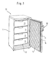
- a household freezer 10 is shown, the heat-insulating Housing 11 has a freezer compartment 12, which for receiving Frozen food containers 13 arranged one above the other in a drawer-like manner serves, and which is accessible via an access opening in the housing 11.
- the access opening can be covered by a door 14 attached to the housing 11, which in the covered state via a magnetic seal 15 elastic on the edge of the Access opening rests.
- a door handle 20 is provided to open the door 14 is on the stop side opposite side wall 16 .
- the door handle 20 has a straight circular cylinder trained grip part 21, which at its free ends with as recordings 22 serving, in the present case designed as insertion slots-like Exemptions are provided, which are in the direction of the longitudinal axis of the grip part 21 extend and formed open to the end faces 23 thereof are.
- the receptacles 22 are with their extending in the longitudinal direction of the handle part 21 lateral boundary surfaces to an imaginary center axis of the handle part 21 largely arranged at the same distance and dimensioned with respect to their width b that they cut through the lateral surface of the grip part 21 on one side. Across from the severing point remains a wall that serves as a stop 24.
- the Recordings 22 are used for the guided insertion and holding of flat metal profiles with rectangular cross-section holding elements 27, the Material thickness s to the height h of the receptacles 22 and their width x to the length l the recordings 22 is coordinated.
- the holding elements 27 have approximately in the middle of it Length an angled, whereby a holding portion 28 and a fastening portion 29 is formed, of which the fastening portion 29 with two at a distance mutually arranged, formed as through holes mounting holes 30 is provided, with the help of which the door handle 20 with not shown Fasteners on the door body of the door 14 can be fixed.
- the mounting section 29 opposite holding section 28 serves to hold the handle part 21 on the holding elements 27.
- the free end of the holding section 28 is in the Recordings 22 inserted, the depth of insertion by striking the front of the holding section 28 is limited to the stop wall 24.
- the handle part 41 is formed as a straight circular cylinder and at its free Provide ends with receptacles 42 designed as blind-hole-like recesses is.
- the receptacles 42 consist of a radially inserted into the handle part 41 Guide slot 43 and an immediately following, in the present Case, a receiving space 44 having a circular cross section, which is arranged concentrically to the central axis of the handle part 41. Both the Receiving space 44 and the guide slot 43 are to the end faces of the Handle part 41 formed open edge.
- the handle part 41 is for forming the door handle 40 can be joined together with holding elements 45, which have an angled one, for example have made of a flat metal section, which by the angling into a holding section 46 and a fastening section 47 is divided, of which the latter with two spaced apart, as Through holes trained mounting holes 48 is provided.
- the holding section 46 is cylindrical at its free end with a cross section trained, provided as a holding part 49 bolt, which is radial to it Central axis is fixed at the free end of the holding section 46 and which with its end face facing away from the grip part 41 is flush with the corresponding end face Side surface of the handle part 41 completes.
- the holding part 49 has a length I, which is larger than the width b of the holding element 45, so that a certain Protrusion is formed, which essentially corresponds to the length of the blind hole adapted with a circular cross-section receiving space 44 is. Furthermore, the circular cylindrical holding part 49 is in terms of its outer diameter matched to the inside diameter of the receiving space 44 so that that in the inserted state within the receiving space 44 section of the Holding part 49 is held therein essentially free of play.
- the focus on the recording room 44 subsequent guide slot 43 is essentially in terms of its height h also matched to the material thickness s of the holding element 45, so that when Insertion process of the holding element 45 (in the direction of the arrow) is a kind of guide for the holding section 46 is formed within the guide slot 43, the slot length I is adapted to the width b of the holding element 45.
Description
Die Erfindung betrifft einen Türgriff für eine Kühlmöbeltür, insbesondere eine Kühlmöbeltür mit an der Tür festsetzbaren Halteelementen und einem länglich ausgebildeten, einstückigen Griffteil, welches Aufnahmen aufweist, mit welchen es an den Halteelementen gehaltert ist, wobei die Aufnahmen durch einen Führungsschlitz und einen zur Längsachse des Griffteils sich erstreckende, aus dessen freien Enden randoffen ausgebildeten Aufnahmeraum gebildet sind, in welchem an dem freien Endabschnitten der Halteelemente vorgesehene Halteteile angeordnet sind.The invention relates to a door handle for a refrigerator door, in particular one Refrigerator door with holding elements that can be fixed to the door and an elongated one trained, one-piece handle part, which has receptacles with which it the holding elements is held, the receptacles through a guide slot and one extending to the longitudinal axis of the handle part, from the free ends thereof open-formed receiving space are formed, in which on the free End portions of the holding elements provided holding parts are arranged.
Ein derartiger Türgriff ist aus der DE-U-94 09 850 bekannt. Dieser bekannte Türgriff benötigt zur Halterung seiner Halteteile einen in den Aufnahmeraum des Griffteils einzubringenden Spanndorn, der zusammen mit einer Spannmutter zur Halterung der Halteteile innerhalb des Aufnahmeraums des Griffteils dient. Durch die mit Hilfe des Spanndorns erzielbare Aufspreizung wird aber lediglich das von Spanndorn aufgeweitete Ende in Anlage mit den Innenwänden des Aufnahmeraums des Griffteils gebracht. Der andere Endabschnitt des Spanndorns ist demzufolge zwangsläufig mit Spiel innerhalb des Aufnahmeraums angeordnet.Such a door handle is known from DE-U-94 09 850. This well-known door handle Requires one in the receiving space of the handle part to hold its holding parts Inserting mandrel, which together with a clamping nut to hold the Holding parts within the receiving space of the handle part is used. By using the The spreading mandrel that can be achieved is only that of the mandrel flared end in contact with the inner walls of the receiving space of the handle part brought. The other end section of the mandrel is therefore inevitable Game arranged within the recording room.
Weiterhin ist es bei Kühlgeräten wie Kühl- oder Gefrierschränken zum Einsatz kommenden Türgriffen in die Praxis umgesetzt, Türgriffe zu deren Befestigung an den Türen der Kältegeräte mit Halteelementen auszustatten, die ein kreiszylindrisch ausgebildetes Griffteil des Türgriffes an deren freien Enden aufnehmen. Hierzu sind an den freien Enden des Griffteils Aufnahmen in Form von stufenartig zurückgesetzten Ansätzen vorgesehen, welche von an den Halteelementen vorgesehenen hülsenähnlichen Rohrstützen zur Halterung des Griffteils manchettenartig umgriffen sind, so dass leicht zur Verschmutzung neigende, fugenbehaftete Übergänge zwischen dem Griffteil und den Halteelementen erzeugt sind.It is also used in cooling devices such as refrigerators or freezers coming door handles put into practice, door handles for their attachment to the Equip the doors of the refrigeration devices with holding elements, which are circular cylindrical Take up trained handle part of the door handle at its free ends. For this are on the free ends of the handle part recordings in the form of step-like reset Approaches provided, which are provided on the holding elements sleeve-like pipe supports for holding the grip part encircled like a cuff are, so that the joints are slightly prone to contamination are generated between the handle part and the holding elements.
Aus der DE-U-91 14 753 ist ein Griff für ein Möbel bekannt, der eine Halteplatte und ein von der Halteplatte innenseitig getragenes Griffteil besitzt, wobei die Halteplatte an der Form des zu betätigenden Möbelteils angepaßt ist.From DE-U-91 14 753 a handle for a piece of furniture is known which has a holding plate and has a handle part carried on the inside by the holding plate, the holding plate being attached is adapted to the shape of the furniture part to be operated.
Der Erfindung liegt die Aufgabe zugrunde, den Türgriff gemäß des Oberbegriffs des Anspruchs 1 mit einfachen konstruktiven Maßnahmen zu verbessern.The invention has for its object the door handle according to the preamble of Claim 1 to improve with simple constructive measures.
Diese Aufgabe wird gemäß der Erfindung dadurch gelöst, daß die Halteteile in den Aufnahmeraum zumindest weitestgehend konturenangepaßt derart einfügbar sind, dass die Halteteile innerhalb des Aufnahmeraums im wesentlichen spielfrei gehalten sind.This object is achieved according to the invention in that the holding parts in the Recording space can be inserted at least as far as possible in line with the contours, that the holding parts are kept essentially free of play within the receiving space are.
Durch die erfindungsgemäße Lösung ist ein fugenfreier Übergang des Griffteils zu den Halteelementen ausgebildet und der Einsatz eines über seine Haltestellen hinaus durchgehend verlaufenden Griffteiles möglich, so dass durch die Haltemaßnahmen des Griffteiles erzeugte, zur bevorzugten Ablagerung von Schmutz geeignete Übergänge vermieden sind. Des weiteren können Bearbeitungsvorgänge zur Beseitigung gegebenfalls scharfkantiger und somit verletzungsträchtiger Übergänge zwischen dem Griffteil und den Halteelementen entfallen. Darüber hinaus ist durch eine derartige Lösung sichergestellt, dass das Griffteil auch bei in der Massenfertigung der Konsumgüterbranche durchwegs auftretenden unzulässigen Toleranzabweichungen stets verdrehsicher mit den Halteelementen verbunden ist. Außerdem ist durch die erfindungsgemäße Lösung das Griffteil besonders robust und langzeitstabil mit den Halteelementen verbunden. Dabei erübrigt sich eine gesonderte Haltemaßnahme zwischen den Halteelementen und dem Griffteil, da diese Haltemaßnahme durch die in den Aufnahmeraum eingefügten, senkrecht zur Fügerichtung in den Führungsschlitz angeordneten Halteteilen erzeugt ist.The solution according to the invention enables a seamless transition of the handle part to the Holding elements trained and the use of one beyond its stops continuous handle part possible, so that through the holding measures the handle part generated, suitable for the preferred deposition of dirt Transitions are avoided. Furthermore, processing operations for Eliminate any sharp-edged and therefore injured transitions between the handle and the holding elements. In addition, is by Such a solution ensures that the handle part even in mass production in the consumer goods industry consistently occurring inadmissible Tolerance deviations are always non-rotatably connected to the holding elements. In addition, the handle part is particularly robust and by the solution according to the invention long-term stable connected with the holding elements. There is no need for a separate one Holding measure between the holding elements and the handle part, since this Holding measure through the inserted in the recording space, perpendicular to Joining direction in the guide slot arranged holding parts is generated.
Fertigungstechnisch besonders einfach und kostengünstig herstellbar sind die Halteelemente, wenn nach einer nächsten vorteilhaften Ausgestaltung des Gegenstandes der Erfindung vorgesehen ist, dass die Halteelemente aus flachprofiligen Halbzeugen gebildet sind.The are technically particularly simple and inexpensive to manufacture Holding elements if, according to a next advantageous embodiment of the The object of the invention is that the holding elements flat-profile semi-finished products are formed.
Fertigungstechnisch besonders einfach in unterschiedlichen Größen herstellbar ist der Aufnahmeraum, wenn nach einer weiteren bevorzugten Ausführungsform des Gegenstandes der Erfindung vorgesehen ist, dass der Aufnahmeraum als eine von den freien Enden des Griffteiles her eingebrachte kreiszylindrische Sacklochbohrung ausgebildet ist.In terms of manufacturing technology, it is particularly easy to produce in different sizes Recording room if, according to a further preferred embodiment of the The object of the invention is that the receiving space as one of the free ends of the handle part introduced circular cylindrical blind hole is trained.
Nach einer weiteren bevorzugten Ausführungsform des Gegenstandes der Erfindung ist vorgesehen, dass das Griffteil einen kreisförmigen Querschnitt aufweist.According to a further preferred embodiment of the subject of the invention it is provided that the grip part has a circular cross section.
Durch eine derartige Ausgestaltung des Griffteiles können preisgünstige, entsprechend der gewünschten Grifflänge abgelenkte Halbzeuge aus unterschiedlichem Materialien zum Einsatz kommen.Such a design of the handle part allows inexpensive, deflected semi-finished products according to the desired handle length different materials are used.
Entsprechend einer weiteren bevorzugten Ausführungsform des Gegenstandes der Erfindung ist vorgesehen, dass die Aufnahmen einen rechteckförmigen, an die Kontur der Halteelemente angepaßten Längsschnitt aufweisen, dessen längere Rechteckseiten im wesentlichen in Richtung zur Längsachse des Griffteiles ausgerichtet sind.According to a further preferred embodiment of the subject of The invention provides that the receptacles have a rectangular shape to match the contour of the holding elements have adapted longitudinal section, the longer Rectangular sides essentially in the direction of the longitudinal axis of the handle part are aligned.
Gemäß einer letzten bevorzugten Ausführungsform des Gegenstandes der Erfindung ist vorgesehen, dass das Griffteil aus Werkstoffen wie Metall, Holz oder Kunststoff gebildet ist, jedoch vorzugsweise aus Metall besteht.According to a last preferred embodiment of the subject of the invention it is provided that the handle part made of materials such as metal, wood or plastic is formed, but preferably consists of metal.
Die Erfindung ist in der nachfolgenden Beschreibung anhand von zwei in der beigefügten Zeichnung vereinfacht dargestellten Ausführungsbeispielen erläutert.
- Fig. 1
- einen Haushaltsgefrierschrank mit an seiner geöffneten Tür angeordneten Türgriff in raumbildlicher Darstellung von vorne,
- Fig. 2
- eine erste Ausführungsform des Türgriffes mit einem einseitig von einer seiner Aufnahmen abgezogenen Halteelement, in raumbildlicher Ansicht von oben und
- Fig. 3
- eine alternative Ausführungsform des Türgriffes mit einem einseitig von einer seiner Aufnahmen abgezogenen Halteelement, in raumbildlicher Ansicht von oben.
- Fig. 1
- a household freezer with a door handle arranged on its open door in a spatial representation from the front,
- Fig. 2
- a first embodiment of the door handle with a holding element pulled off on one side from one of its receptacles, in a spatial view from above and
- Fig. 3
- an alternative embodiment of the door handle with a holding element pulled off on one side from one of its receptacles, in a spatial view from above.
Gemäß Fig.1 ist ein Haushaltsgefrierschrank 10 gezeigt, dessen wärmeisolierend ausgebildetes
Gehäuse 11 einen Gefrierraum 12 aufweist, welcher zur Aufnahme von
übereinander angeordneten, schubladenartig ausgebildeten Gefriergutbehältern 13
dient, und welcher über eine Zugangsöffnung im Gehäuse 11 zugänglich ist. Die Zugangsöffnung
ist von einer am Gehäuse 11 angeschlagenen Tür 14 abdeckbar,
welche im abgedeckten Zustand über eine Magnetdichtung 15 elastisch am Rand der
Zugangsöffnung aufliegt. Zum Öffnen der Tür 14 ist an seiner der Anschlagseite
gegenüberliegenden Seitenwange 16 ein Türgriff 20 vorgesehen.According to Figure 1, a
Wie insbesondere aus Fig.2 hervorgeht, weist der Türgriff 20 ein als gerader Kreiszylinder
ausgebildetes Griffteil 21 auf, welches an seinen freien Enden mit als Aufnahmen
22 dienenden, im vorliegenden Fall als Einführschlitze ausgebildeten sacklochähnlichen
Freisparungen versehen ist, welche sich in Richtung der Längsachse
des Griffteiles 21 erstrecken und randoffen zu dessen Stirnseiten 23 hin ausgebildet
sind. Die Aufnahmen 22 sind mit ihren in Längsrichtung des Griffteiles 21 verlaufenden
seitlichen Begrenzungsflächen zu einer gedachten Zentrumsachse des Griffteiles 21
weitestgehend in gleichem Abstand angeordnet und hinsichtlich ihrer Breite b so bemessen,
daß sie einseitig die Mantelfläche des Griffteiles 21 durchtrennen. Gegenüber
der Durchtrennstelle bleibt eine Wandung bestehen, die als Anschlag 24 dient. Senkrecht
zu den im Längsschnitt rechteckförmig ausgebildeten Aufnahmen 22 ist eine mit
Abstand von den Stirnseiten 23 zurückversetzte Gewindebohrung 25 vorgesehen, welche
von der Mantelfläche des Griffteiles 21 bis hin zu den Aufnahmen 22 verläuft und
in welche eine als Klemmschraube 26 dienende Madenschraube einbringbar ist. Die
Aufnahmen 22 dienen zur geführten Einbringung und Halterung von aus Metallflachprofilen
mit rechteckförmigem Querschnitt hergestellten Halteelementen 27, deren
Materialstärke s auf die Höhe h der Aufnahmen 22 und deren Breite x auf die Länge l
der Aufnahmen 22 abgestimmt ist. Die Halteelemente 27 weisen etwa in der Mitte ihrer
Länge eine Abwinklung auf, wodurch ein Halteabschnitt 28 und ein Befestigungsabschnitt
29 gebildet ist, von denen der Befestigungsabschnitt 29 mit zwei im Abstand
zueinander angeordneten, als Durchgangsbohrungen ausgebildete Befestigungsbohrungen
30 versehen ist, mit deren Hilfe der Türgriff 20 mit nicht näher dargestellten
Befestigungsmitteln am Türkorpus der Tür 14 festsetzbar ist. Der dem Befestigungsabschnitt
29 gegenüberliegende Halteabschnitt 28 dient zur Halterung des Griffteiles
21 an den Halteelementen 27. Hierzu ist das freie Ende des Halteabschnitts 28 in die
Aufnahmen 22 eingefügt, wobei die Einfügetiefe durch das Anschlagen der Stirnseite
des Halteabschnittes 28 an der Anschlagwand 24 begrenzt ist. Im positionsrichtigen
Fügezustand, in welchem der Halteabschnitt 28 mit seiner außenliegenden Längsseite
flächenbündig mit der Stirnseite 23 des Griffteiles 21 abschließt, wird das Halteelement
mittels den form- und/oder kraftschlüssig am Halteabschnitt 28 angreifenden
Klemmschrauben 26 fixiert, wobei die Klemmschrauben im Fixierzustand vollkommen
von der Gewindebohrung 25 aufgenommen sind, so daß eine weitestgehend glattflächige
Oberfläche für das Griffteil 21 gebildet ist.As can be seen in particular from Figure 2, the
In Fig. 3 ist entsprechend einem zweiten Ausführungsbeispiel ein Türgriff 40 gezeigt,
dessen Griffteil 41 als gerader Kreiszylinder ausgebildet ist und an seinen freien
Enden mit als sacklochähnliche Freisparungen ausgebildete Aufnahmen 42 versehen
ist. Die Aufnahmen 42 setzen sich aus einem radial in das Griffteil 41 eingebrachten
Führungsschlitz 43 und einen unmittelbar sich daran anschließenden, im vorliegenden
Fall, einen kreisförmigen Querschnitt aufweisenden Aufnahmeraum 44 zusammen,
welcher konzentrisch zur Mittelachse des Griffteiles 41 angeordnet ist. Sowohl der
Aufnahmeraum 44 als auch der Führungsschlitz 43 sind zu den Stirnflächen des
Griffteiles 41 hin randoffen ausgebildet. Das Griffteil 41 ist zur Ausbildung des Türgriffes
40 mit Halteelementen 45 zusammenfügbar, welche einen abgewinkelten, beispielsweise
aus einem Metallflachprofil gefertigten Abschnitt aufweisen, welcher durch
die Abwinklung in einen Halteabschnitt 46 und einen Befestigungsabschnitt 47
unterteilt ist, von denen letzterer mit zwei im Abstand zueinander angeordneten, als
Durchgangsbohrungen ausgebildeten Befestigungsbohrungen 48 versehen ist. Der
Halteabschnitt 46 ist an seinem freien Ende mit einem im Querschnitt kreiszylindrisch
ausgebildeten, als Halteteil 49 dienenden Bolzen versehen, welcher radial zu seiner
Mittelachse am freien Ende des Halteabschnitts 46 festgesetzt ist und welcher mit seiner
vom Griffteil 41 abgewandten Stirnfläche bündig mit der dazu korrespondierenden
Seitenfläche des Griffteiles 41 abschließt. Das Halteteil 49 weist eine Länge I auf,
welche größer als die Breite b des Halteelementes 45 bemessen ist, so daß ein gewisser
Überstand gebildet ist, welcher im wesentlichen an die Länge des als Sacklochbohrung
mit kreisförmigem Querschnitt ausgebildeten Aufnahmeraumes 44 angepaßt
ist. Weiterhin ist das kreiszylindrische Halteteil 49 hinsichtlich seines Außendurchmessers
auf den Innendurchmesser des Aufnahmeraums 44 so abgestimmt, daß
der im Einfügezustand innerhalb des Aufnahmeraumes 44 befindliche Abschnitt des
Halteteiles 49 darin im wesentlichen spielfrei gehalten ist. Der sich an den Aufnahmeraum
44 anschließende Führungsschlitz 43 ist hinsichtlich seiner Höhe h im wesentlichen
auch auf die Materialstärke s des Halteelementes 45 abgestimmt, so daß beim
Einführvorgang des Halteelementes 45 (in Pfeilrichtung) eine Art Führung für den Halteabschnitt
46 innerhalb des Führungsschlitzes 43 gebildet ist, dessen Schlitzlänge I
an die Breite b des Halteelementes 45 angepaßt ist. Hierdurch schließt das Halteelement
45 im Einfügezustand mit seiner vom Griffteil 41 abgewandten Außenseite im
wesentlichen flächenbündig mit der korrespondierenden Stirnfläche des Griffteiles 41
ab. Nach dem Einfügen der Halteelemente 45 in die Aufnahmen 42 des Griffteiles 41
wird der somit komplettierte Türgriff 40 mittels der am Befestigungsabschnitt 47 vorgesehenen
Befestigungsbohrungen 48 am Türkorpus der Tür 14 mittels nicht näher
dargestellter Befestigungsmittel festgesetzt.3 shows a
Für die Griffteile 41 eignen sich neben verschiedenen Metallen auch Werkstoffe wie
Holz oder Kunststoff.In addition to various metals, materials such as are also suitable for the
Claims (5)
- Door handle (20, 40) for a door of an item of furniture, particularly a door (14) of an item of cooling furniture, with retaining elements (27, 45) fixable to the door (14) and a grip part (21, 41) of integral construction which is formed to be elongate and which has receptacles (22, 42) by which it is retained at the retaining elements (27, 45), wherein the receptacles (22, 42) are formed by a guide slot (22, 43) and a receiving space (22, 44) which extends relative to the longitudinal axis of the grip part (21, 41), is formed to be open at the edge at the free ends of the grip part and in which retaining members (28, 49) provided at the free end portions of the retaining elements (27, 45) are arranged, characterised in that the retaining members (28, 49) are inserted into the receiving space (22, 44) to be at least substantially matched in contour to the receiving space in such a manner that the retaining members (28, 49) are held substantially free of play within the receiving space (22, 44) by the wall of the receiving space.
- Door handle according to claim 1, characterised in that the retaining elements (45) are formed from a flat-profiled semi-finished component.
- Door handle according to claim 1, characterised in that the receiving space (44) is formed as a circularly cylindrical blind bore produced from the free ends of the grip part (41).
- Door handle according to one of claims 1 to 3, characterised in that the grip part (41) has a circular cross-section.
- Door handle according to one of claims 1 to 4, characterised in that the grip part (41) is formed from materials such as metal, wood or synthetic material, but preferably consists of metal.
Applications Claiming Priority (3)
| Application Number | Priority Date | Filing Date | Title |
|---|---|---|---|
| DE19650776A DE19650776A1 (en) | 1996-12-06 | 1996-12-06 | Door handle for a furniture door, in particular a refrigerator door |
| DE19650776 | 1996-12-06 | ||
| PCT/EP1997/006722 WO1998024343A1 (en) | 1996-12-06 | 1997-12-01 | Door handle for furniture unit, specially a refrigerator |
Publications (2)
| Publication Number | Publication Date |
|---|---|
| EP0948275A1 EP0948275A1 (en) | 1999-10-13 |
| EP0948275B1 true EP0948275B1 (en) | 2003-04-02 |
Family
ID=7813909
Family Applications (1)
| Application Number | Title | Priority Date | Filing Date |
|---|---|---|---|
| EP97952842A Expired - Lifetime EP0948275B1 (en) | 1996-12-06 | 1997-12-01 | Door handle for furniture unit, specially a refrigerator |
Country Status (7)
| Country | Link |
|---|---|
| EP (1) | EP0948275B1 (en) |
| BR (1) | BR9713566A (en) |
| DE (2) | DE19650776A1 (en) |
| DK (1) | DK0948275T3 (en) |
| ES (1) | ES2196387T3 (en) |
| TR (1) | TR199901252T2 (en) |
| WO (1) | WO1998024343A1 (en) |
Cited By (2)
| Publication number | Priority date | Publication date | Assignee | Title |
|---|---|---|---|---|
| WO2010139537A1 (en) * | 2009-06-03 | 2010-12-09 | BSH Bosch und Siemens Hausgeräte GmbH | Handle for an appliance housing |
| DE102011087757A1 (en) * | 2011-12-05 | 2013-06-06 | BSH Bosch und Siemens Hausgeräte GmbH | Door handle for door of household appliance e.g. microwave oven,, has gripping blocks that are inserted into open ends of profiled handlebar |
Families Citing this family (14)
| Publication number | Priority date | Publication date | Assignee | Title |
|---|---|---|---|---|
| DE20007765U1 (en) * | 2000-04-28 | 2001-09-13 | Liebherr Hausgeraete | Door handle, preferably handle for the door of a refrigerator or freezer |
| DE20012698U1 (en) * | 2000-07-21 | 2001-11-29 | Liebherr Hausgeraete | Fridge or freezer with a door with a handle |
| DE10303734B4 (en) * | 2003-01-30 | 2009-05-07 | BSH Bosch und Siemens Hausgeräte GmbH | Handle for a household appliance |
| DE10308629A1 (en) | 2003-02-27 | 2004-09-09 | BSH Bosch und Siemens Hausgeräte GmbH | door handle |
| DE602004009183T2 (en) * | 2003-06-30 | 2008-07-03 | Arcelik Anonim Sirketi, Tuzla | HANDLE |
| KR100555804B1 (en) * | 2004-08-11 | 2006-03-03 | 엘지전자 주식회사 | Door handle for refrigerator |
| DE202005014384U1 (en) * | 2005-09-12 | 2005-11-17 | BSH Bosch und Siemens Hausgeräte GmbH | A door grip for refrigeration appliances is assembled from two components which may be assembled by a user to suit left or right hand opening |
| DE102006042176A1 (en) * | 2006-09-08 | 2008-03-27 | BSH Bosch und Siemens Hausgeräte GmbH | Handle for a household appliance |
| DE202007013032U1 (en) * | 2007-09-17 | 2007-12-27 | BSH Bosch und Siemens Hausgeräte GmbH | Door handle for a household appliance |
| KR101639437B1 (en) * | 2009-11-12 | 2016-07-13 | 엘지전자 주식회사 | A structure for assembling door handle of home appliance |
| DE102011087754A1 (en) * | 2011-12-05 | 2013-06-06 | BSH Bosch und Siemens Hausgeräte GmbH | Door handle secured at front of door in cooking appliance e.g. microwave oven, has grip bracket comprising support portion which is provided outside the handle section for attachment of door handle |
| DE102011087756A1 (en) * | 2011-12-05 | 2013-06-06 | BSH Bosch und Siemens Hausgeräte GmbH | Handle for household appliance door e.g. baking oven door, has handle profile designed as tube, and handle supports made of aluminum, and designed as extruded parts or solid bodies, where supports form hollow space |
| EP3040660B1 (en) | 2014-12-30 | 2017-05-31 | Whirlpool EMEA S.p.A | Door handle for a furniture unit, in particular a refrigerator |
| KR200490421Y1 (en) * | 2018-12-26 | 2019-11-08 | 김부성 | Movable table |
Family Cites Families (3)
| Publication number | Priority date | Publication date | Assignee | Title |
|---|---|---|---|---|
| DE9114753U1 (en) * | 1991-11-27 | 1992-03-05 | Moebelwerke Moser Gmbh & Co Kg, 7230 Schramberg, De | |
| DE4225525C2 (en) * | 1992-08-01 | 1996-04-11 | Schulte Sam & Co | Handle |
| DE9409850U1 (en) * | 1994-06-22 | 1994-08-04 | Metallwerk Sundern Otto Brumbe | Handle for furniture |
-
1996
- 1996-12-06 DE DE19650776A patent/DE19650776A1/en not_active Withdrawn
-
1997
- 1997-12-01 EP EP97952842A patent/EP0948275B1/en not_active Expired - Lifetime
- 1997-12-01 DE DE59709724T patent/DE59709724D1/en not_active Expired - Lifetime
- 1997-12-01 ES ES97952842T patent/ES2196387T3/en not_active Expired - Lifetime
- 1997-12-01 WO PCT/EP1997/006722 patent/WO1998024343A1/en active IP Right Grant
- 1997-12-01 DK DK97952842T patent/DK0948275T3/en active
- 1997-12-01 BR BR9713566-6A patent/BR9713566A/en not_active IP Right Cessation
- 1997-12-01 TR TR1999/01252T patent/TR199901252T2/en unknown
Cited By (3)
| Publication number | Priority date | Publication date | Assignee | Title |
|---|---|---|---|---|
| WO2010139537A1 (en) * | 2009-06-03 | 2010-12-09 | BSH Bosch und Siemens Hausgeräte GmbH | Handle for an appliance housing |
| DE102009026663A1 (en) | 2009-06-03 | 2010-12-09 | BSH Bosch und Siemens Hausgeräte GmbH | Handle for a device housing |
| DE102011087757A1 (en) * | 2011-12-05 | 2013-06-06 | BSH Bosch und Siemens Hausgeräte GmbH | Door handle for door of household appliance e.g. microwave oven,, has gripping blocks that are inserted into open ends of profiled handlebar |
Also Published As
| Publication number | Publication date |
|---|---|
| WO1998024343A1 (en) | 1998-06-11 |
| EP0948275A1 (en) | 1999-10-13 |
| DK0948275T3 (en) | 2003-07-28 |
| BR9713566A (en) | 2000-03-14 |
| ES2196387T3 (en) | 2003-12-16 |
| TR199901252T2 (en) | 1999-09-21 |
| DE59709724D1 (en) | 2003-05-08 |
| DE19650776A1 (en) | 1998-06-10 |
Similar Documents
| Publication | Publication Date | Title |
|---|---|---|
| EP0948275B1 (en) | Door handle for furniture unit, specially a refrigerator | |
| DE102008044385A1 (en) | Handle holder, domestic appliance and method for attaching a door handle | |
| EP3476252B1 (en) | Device for holding a shelf base to a shelf wall unit and shelf with such a holding device | |
| WO2004075690A1 (en) | Door handle | |
| DE4032426C2 (en) | Bracket fitting for drawer pull-out guides | |
| DE202005012342U1 (en) | A plastic storage container for refrigeration appliances has a front wall comprising extruded and injection moulded parts with facility for easy assembly | |
| EP3283776B1 (en) | Toggle dowel | |
| DE19751310A1 (en) | Refrigerator | |
| EP0891524B1 (en) | Refrigerator | |
| AT406999B (en) | BRACKET ARRANGEMENT FOR DRAWER SHELVES ON THE SIDEWALLS OF THE DRAWER | |
| DE29624454U1 (en) | Door handle for furniture door esp. refrigerator door - has holding elements attached to door and elongated one-piece handle part with holders with which it is attached to holding elements, holders being blind hole recesses formed in handle part | |
| DE3104186C1 (en) | Refrigerator, especially household refrigerator or the like. | |
| DE2033042A1 (en) | Gear for espagnolette fittings | |
| EP1379819B1 (en) | Storage container for refrigerators | |
| DE20307353U1 (en) | Fitting for a sliding drawer, to lock the rear wall to the side walls, has matching structures at the fitting and the wall to lock together in a positive fit and be secured by fastening screws | |
| WO2007128515A2 (en) | Connecting device comprising a locking element | |
| DE19717188C1 (en) | Rotary or push-rod type furniture-lock | |
| DE102010013529A1 (en) | handle assembly | |
| EP3571959A1 (en) | Locking device for a drawer | |
| EP0920828B1 (en) | Utility object in the form of a piece of equipment especially a towelholder | |
| DE3101228A1 (en) | Furniture hinge with a means for limiting the opening angle | |
| DE102020208803A1 (en) | Household appliance device with at least one drawer front | |
| EP0972904B1 (en) | Cabinet door frame with snap-in fitting element | |
| DE102019212729A1 (en) | Inner container for a household refrigerator with additional, removable decorative plate, as well as household refrigerator and method | |
| DE202005007930U1 (en) | Grip recess for installation in cut in thin wall includes receiver for catch within range of side panel such as side panel positioned at acute angle |
Legal Events
| Date | Code | Title | Description |
|---|---|---|---|
| PUAI | Public reference made under article 153(3) epc to a published international application that has entered the european phase |
Free format text: ORIGINAL CODE: 0009012 |
|
| 17P | Request for examination filed |
Effective date: 19990705 |
|
| AK | Designated contracting states |
Kind code of ref document: A1 Designated state(s): DE DK ES FR GB IT |
|
| 17Q | First examination report despatched |
Effective date: 20010914 |
|
| GRAH | Despatch of communication of intention to grant a patent |
Free format text: ORIGINAL CODE: EPIDOS IGRA |
|
| GRAH | Despatch of communication of intention to grant a patent |
Free format text: ORIGINAL CODE: EPIDOS IGRA |
|
| GRAA | (expected) grant |
Free format text: ORIGINAL CODE: 0009210 |
|
| AK | Designated contracting states |
Designated state(s): DE DK ES FR GB IT |
|
| REG | Reference to a national code |
Ref country code: GB Ref legal event code: FG4D Free format text: NOT ENGLISH |
|
| REF | Corresponds to: |
Ref document number: 59709724 Country of ref document: DE Date of ref document: 20030508 Kind code of ref document: P |
|
| REG | Reference to a national code |
Ref country code: DK Ref legal event code: T3 |
|
| GBT | Gb: translation of ep patent filed (gb section 77(6)(a)/1977) |
Effective date: 20030801 |
|
| REG | Reference to a national code |
Ref country code: ES Ref legal event code: FG2A Ref document number: 2196387 Country of ref document: ES Kind code of ref document: T3 |
|
| PGFP | Annual fee paid to national office [announced via postgrant information from national office to epo] |
Ref country code: DK Payment date: 20031229 Year of fee payment: 7 |
|
| ET | Fr: translation filed | ||
| PLBE | No opposition filed within time limit |
Free format text: ORIGINAL CODE: 0009261 |
|
| STAA | Information on the status of an ep patent application or granted ep patent |
Free format text: STATUS: NO OPPOSITION FILED WITHIN TIME LIMIT |
|
| 26N | No opposition filed |
Effective date: 20040105 |
|
| PG25 | Lapsed in a contracting state [announced via postgrant information from national office to epo] |
Ref country code: DK Free format text: LAPSE BECAUSE OF NON-PAYMENT OF DUE FEES Effective date: 20050103 |
|
| REG | Reference to a national code |
Ref country code: DK Ref legal event code: EBP |
|
| REG | Reference to a national code |
Ref country code: DE Ref legal event code: R081 Ref document number: 59709724 Country of ref document: DE Owner name: BSH HAUSGERAETE GMBH, DE Free format text: FORMER OWNER: BSH BOSCH UND SIEMENS HAUSGERAETE GMBH, 81739 MUENCHEN, DE Effective date: 20150402 |
|
| REG | Reference to a national code |
Ref country code: ES Ref legal event code: PC2A Owner name: BSH HAUSGERATE GMBH Effective date: 20150527 |
|
| REG | Reference to a national code |
Ref country code: FR Ref legal event code: CD Owner name: BSH HAUSGERATE GMBH Effective date: 20151022 |
|
| REG | Reference to a national code |
Ref country code: FR Ref legal event code: PLFP Year of fee payment: 19 |
|
| REG | Reference to a national code |
Ref country code: FR Ref legal event code: PLFP Year of fee payment: 20 |
|
| PGFP | Annual fee paid to national office [announced via postgrant information from national office to epo] |
Ref country code: GB Payment date: 20161222 Year of fee payment: 20 |
|
| PGFP | Annual fee paid to national office [announced via postgrant information from national office to epo] |
Ref country code: ES Payment date: 20161221 Year of fee payment: 20 Ref country code: IT Payment date: 20161220 Year of fee payment: 20 Ref country code: FR Payment date: 20161221 Year of fee payment: 20 |
|
| PGFP | Annual fee paid to national office [announced via postgrant information from national office to epo] |
Ref country code: DE Payment date: 20161231 Year of fee payment: 20 |
|
| REG | Reference to a national code |
Ref country code: DE Ref legal event code: R071 Ref document number: 59709724 Country of ref document: DE |
|
| REG | Reference to a national code |
Ref country code: GB Ref legal event code: PE20 Expiry date: 20171130 |
|
| PG25 | Lapsed in a contracting state [announced via postgrant information from national office to epo] |
Ref country code: GB Free format text: LAPSE BECAUSE OF EXPIRATION OF PROTECTION Effective date: 20171130 |
|
| REG | Reference to a national code |
Ref country code: ES Ref legal event code: FD2A Effective date: 20180508 |
|
| PG25 | Lapsed in a contracting state [announced via postgrant information from national office to epo] |
Ref country code: ES Free format text: LAPSE BECAUSE OF EXPIRATION OF PROTECTION Effective date: 20171202 |