EP0947769A2 - Blaubrenner - Google Patents
Blaubrenner Download PDFInfo
- Publication number
- EP0947769A2 EP0947769A2 EP99106458A EP99106458A EP0947769A2 EP 0947769 A2 EP0947769 A2 EP 0947769A2 EP 99106458 A EP99106458 A EP 99106458A EP 99106458 A EP99106458 A EP 99106458A EP 0947769 A2 EP0947769 A2 EP 0947769A2
- Authority
- EP
- European Patent Office
- Prior art keywords
- flame tube
- flame
- exhaust gas
- tube
- gas recirculation
- Prior art date
- Legal status (The legal status is an assumption and is not a legal conclusion. Google has not performed a legal analysis and makes no representation as to the accuracy of the status listed.)
- Withdrawn
Links
Images

Classifications
-
- F—MECHANICAL ENGINEERING; LIGHTING; HEATING; WEAPONS; BLASTING
- F23—COMBUSTION APPARATUS; COMBUSTION PROCESSES
- F23C—METHODS OR APPARATUS FOR COMBUSTION USING FLUID FUEL OR SOLID FUEL SUSPENDED IN A CARRIER GAS OR AIR
- F23C9/00—Combustion apparatus characterised by arrangements for returning combustion products or flue gases to the combustion chamber
- F23C9/006—Combustion apparatus characterised by arrangements for returning combustion products or flue gases to the combustion chamber the recirculation taking place in the combustion chamber
-
- F—MECHANICAL ENGINEERING; LIGHTING; HEATING; WEAPONS; BLASTING
- F23—COMBUSTION APPARATUS; COMBUSTION PROCESSES
- F23D—BURNERS
- F23D11/00—Burners using a direct spraying action of liquid droplets or vaporised liquid into the combustion space
- F23D11/36—Details
- F23D11/40—Mixing tubes; Burner heads
- F23D11/406—Flame stabilising means, e.g. flame holders
-
- F—MECHANICAL ENGINEERING; LIGHTING; HEATING; WEAPONS; BLASTING
- F23—COMBUSTION APPARATUS; COMBUSTION PROCESSES
- F23D—BURNERS
- F23D2209/00—Safety arrangements
- F23D2209/20—Flame lift-off / stability
-
- F—MECHANICAL ENGINEERING; LIGHTING; HEATING; WEAPONS; BLASTING
- F23—COMBUSTION APPARATUS; COMBUSTION PROCESSES
- F23D—BURNERS
- F23D2900/00—Special features of, or arrangements for burners using fluid fuels or solid fuels suspended in a carrier gas
- F23D2900/11402—Airflow diaphragms at burner nozzle
-
- F—MECHANICAL ENGINEERING; LIGHTING; HEATING; WEAPONS; BLASTING
- F23—COMBUSTION APPARATUS; COMBUSTION PROCESSES
- F23D—BURNERS
- F23D2900/00—Special features of, or arrangements for burners using fluid fuels or solid fuels suspended in a carrier gas
- F23D2900/11403—Flame surrounding tubes in front of burner nozzle
Definitions
- the invention relates to a so-called blue burner for the Equipping boilers.
- Blue burners according to the preamble of claim 1 are known, for example, according to DE 42 09 922 A1, this burner comprising an additional sleeve within its flame tube, the area of the nozzle and immediately behind it, which serves to additionally recirculate the exhaust gas from the boiler combustion chamber Exhaust gas recirculation also takes place within the flame tube.
- a burner is also known, the flame tube of which has no exhaust gas recirculation openings, but is at a distance of a third of its length from the flame tube opening to the nozzle, a circumferential, inwardly directed bead through which on the one hand flow separations and thus itself subsequent vortices for flame stabilization are brought about, but this, on the other hand, leads, at least to a limited extent, upstream of the bead to exhaust gas backflow within the flame tube.
- flame stabilization is provided by swirling in the funnel-shaped "flame tube".
- the flame in the flame tube is stabilized or burns in the flame tube, the ignition speed in the mixture (oil, air, exhaust gas) being equal to the flow velocity inside the flame tube opposite to the end of the flame tube.
- Local ignition sources such as a glowing flame tube for changing the ignition speed
- / or local backflow zones change in the flow speed
- the distance from the burner nozzle to the flame in the flame tube serves as a mixing zone for the fuel, air and recirculated exhaust gas components involved and as an evaporation zone for the injected fuel. In most cases, flue gas flowing back directly from the flame area also results in the flame tube itself.
- stable flames with relatively good pollutant values NOx approx. 85 - 100 mg / kWh
- the sound pressure level of such burners is above approx. 103 db (A).
- the so-called In principle as previously explained, blue burners have two variants knows, namely those where on the one hand the flame in the glowing flame tube burns or is stabilized in it, and on the other hand those with swirl flow inside the burner effecting training, the swirl flow on Centrifuged apart practically at the end of the tube and thereby the flame is stabilized.
- the invention is based on of a burner according to the preamble of claim 1, the task based on simple construction and "cold” or non-glowing "flame tube” (also in the starting phase) To design burners with simple means so that with exhaust gas recirculation essentially only from outside the flame tube the flame with further improved emission and sound pressure values stabilized at the open end of the flame tube.
- the flame is stabilized only downstream in the region of the combustion chamber-side mouth of the flame tube, which therefore no longer represents a flame tube in the sense of the word , but acts as a relatively cold, ie no longer glowing premixing and evaporation pipe for the operating components involved, the required evaporation energy for the atomized fuel particles being entered by the recirculated exhaust gas.
- the introduction of the combustion air is, as mentioned, coordinated with the openings on the flame tube for the external exhaust gas recirculation from the boiler combustion chamber in such a way that a block-like flow profile is formed which has no or only very small return flow zones within the "flame tube", which will be explained in more detail. Due to the known division of the flow process or the flow path to the flame area into the different zones mentioned above (premixing and exhaust gas intake, pre-evaporation, flame stabilization) over a path length of, for example, 150-450 mm (ie 1.2-6.5 x flame tube diameter) and the decisive stabilization of the flame at the end of the "flame tube", significantly higher amounts of exhaust gas can be fed to the combustion.
- the corresponding energy density of the flame decreases as it is displaced to the mouth of the flame tube and, in addition to the higher amounts of exhaust gas supplied, a relatively "colder” flame can also be stabilized.
- the sound pressure level is significantly reduced (approx. ⁇ 100 dB (A)) by shifting the flame to the mouth of the flame tube and the homogeneous preparation of the mixture, because the resonance chamber "flame tube” is decoupled by the flow change placed at the end of the "flame tube” .
- the blue burner still consists of a blower Combustion air supply 1, at the end of which Combustion air screen 5 provided with air flow openings 2 is arranged, at which one with at least one exhaust gas recirculation opening 6 at the level of the arrangement area of the fuel nozzle 3 of a nozzle assembly 4 provided on the combustion chamber side open flame tube 7 connects, which by a fan G and the combustion air supply represented to the air flow openings 2 1 and the dimensioning of the exhaust gas recirculation openings 6 are designed so that the flame tube 7 over the essential Part of its length L as a pre-mixing and pre-evaporation tube works. Only for the sake of completeness Fig. 1 schematically indicates the blower G belonging to the burner.
- the air inflow openings 2 are advantageous, as in 3 indicated, as individual openings in the closest possible allocation evenly arranged on a pitch circle, which is practical leads to an air hose, which has the result that in Ring area between the nozzle and air inlet openings 2 only one very weak or very small vacuum zone arises. It is but also possible, as also indicated by dashed lines, the Air inflow openings 2 in the form of an annular gap 9.
- the embodiment according to 1 preferred, according to which these means 8, as shown, in the form of a cross-sectional expansion 7 '' of the combustion chamber End region of the flame tube 7 are formed.
- Such a cross-sectional expansion 7 '' for its dimensioning a few millimeters in diameter difference to the flame tube diameter suffice, leads to a reduction in speed of the outflowing mixture in this area and thus for stabilization the flame, and completely independent of the itself surrounding geometry adjoining this area.
- the same flame stabilization can also be achieved if the means 8 for stabilization, as shown in FIG. 4,
- the means 8 for stabilization for example, in the form of a wide-mesh grid 8 'made of suitable Forms wire material or, as greatly enlarged in Fig. 5 illustrates, in the form of a rod-shaped, the opening cross-section of the flame tube 7 penetrating element 8 ''.
- a if applicable combined use of such elements 8 ', 8' 'with one Cross-sectional expansion 7 '' can also be considered to be pulled.
Landscapes
- Engineering & Computer Science (AREA)
- Chemical & Material Sciences (AREA)
- Combustion & Propulsion (AREA)
- Mechanical Engineering (AREA)
- General Engineering & Computer Science (AREA)
- Gas Burners (AREA)
Abstract
Description
Der Vollständigkeit halber sei auch noch auf einen sehr aufwendig bauenden Brenner nach der EP 0 617 231 A1 verwiesen, bei dem per Drallströmung im trichterförmig ausgebildeten "Flammrohr" für eine Flammstabilisierung gesorgt wird.
Die Distanz von der Brennerdüse bis zur im Flammrohr stehenden Flamme dient dabei als Mischzone für die beteiligten Betriebsmittelkomponenten Brennstoff, Luft und rückgeführtes Abgas und als Verdampfungszone für den eingedüsten Brennstoff. Rückströmendes Abgas unmittelbar aus dem Flammbereich ergibt sich dabei zum Teil in der Mehrzahl der Fälle auch im Flammrohr selbst. Durch die Anwendung dieser Mechanismen lassen sich stabile Flammen mit relativ guten Schadstoffwerten (NOx ca. 85 - 100 mg/kWh) erreichen. Die Schalldruckpegel solcher Brenner liegen oberhalb von ca. 103 db(A).
Durch die gezielte Abstimmung von axialem Verbrennungsluftimpuls mit Einbringung des Brennstoffs unter nachfolgender Vormischung mit Abgas und nachfolgender Verdampfung in hier sogenannten lokal unterschiedlichen Zonen erfolgt die Stabilisierung der Flamme erst stromab im Bereich der brennkammerseitigen Ausmündung des Flammrohres, das also kein Flammrohr im Sinne des Wortes mehr darstellt, sondern als relativ kalt bleibendes, d.h., nicht mehr glühendes Vormisch- und Verdampfungsrohr für die beteiligten Betriebskomponenten wirkt, wobei die erforderliche Verdampfungsenergie für die verdüsten Brennstoffpartikel durch das rückgeführte Abgas eingetragen wird.
Die Einbringung der Verbrennungsluft ist, wie vorerwähnt, mit den Öffnungen am Flammrohr für die äußere Abgasrezirkulation aus der Heizkesselbrennkammer so abgestimmt, daß ein blockartiges Strömungsprofil entsteht, welches keine oder nur sehr kleine Rückströmzonen innerhalb des "Flammrohres" aufweist, was noch näher erläutert wird.
Durch die an sich bekannte Aufteilung des Strömungsvorganges bzw. des Strömungsweges bis zum Flammbereich in die oben erwähnten, unterschiedlichen Zonen (Vormischung und Abgasansaugung, Vorverdampfung, Flammenstabilisierung) auf einer Weglänge von bspw. 150 - 450 mm (d.h. 1,2 - 6,5 x Flammrohrdurchmesser) und der dabei entscheidend erst nachfolgenden Stabilisierung der Flamme am Ende des "Flammrohres" können wesentlich höhere Abgasmengen der Verbrennung zugeführt werden.
Vorteilhaft erweist sich hier, daß die entsprechende Energiedichte der Flamme durch deren Verlagerung an die Flammrohrausmündung abnimmt und somit neben den höheren, zugeführten Abgasmengen zusätzlich eine relativ "kältere" Flamme stabilisiert werden kann. Außerdem wird der Schalldruckpegel durch die Verlagerung der Flamme an die Flammrohrmündung und die homogene Aufbereitung des Gemisches wesentlich reduziert(ca.<100 dB(A)), weil der Resonanzraum "Flammrohr" durch die an das Ende des "Flammrohres" verlegte Strömungsveränderung abgekoppelt wird.
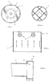
- Fig.1
- einen Längschnitt durch den Brenner in bevorzugter Ausführungsform;
- Fig.2
- einen entsprechenden Schnitt durch den Brenner in anderer Ausführungsform;
- Fig.3
- eine Draufsicht auf die Verbrennungsluftzufuhrblende;
- Fig.4
- eine Ansicht stromauf gegen die Flammrohröffnung;
- Fig.5
- stark vergrößert einen Axialschnitt durch den Endbereich des Flammrohres mit einem stabförmigen Element zur Flammstabilisierung und
- Fig.6
- im Schnitt eine besondere Ausführungsform des Flammrohrendbereiches.
Die Misch- bzw. Vormischzone ist in Fig. 2 mit M, die Verdampfungszone mit V und der Flammbildungsbereich mit F bezeichnet. Da die blaue Flamme, wie kreuzschraffiert als Geschwindigkeitsprofil in Fig.1 angedeutet gewissermaßen als flaches Polster im offenen Ende des Flammrohres 7 brennt, gibt es im Flammrohr 7 keine Rückströmung von Abgasen, sondern nur von außerhalb des Flammrohres aus der Heizkesselbrennkammer B, wie mit Pfeilen angedeutet, wobei die rückströmenden Abgase aufgrund der Sogwirkung im Flammrohr 7 in dieses durch die Abgasrückführöffnungen 6 in das Flammrohr 7 gelangen, sich dort mit der einströmenden Verbrennungsluft mischen und mit dem ausgedüsten Brennstoff in die Verdampfungszone V gelangen, wo die verdüsten Brennstofftröpfchen aufgrund der via Abgas eingetragenen Wärme weitgehend verdampfen und dann als Gemisch aus Luft, rückgeführtem Abgas und weitgehend vergastem Brennstoff in den Flammbereich F am Ende des Flammrohres 7 gelangen.
Im übrigen bietet eine solche Querschnittserweiterung vorteilhafte Weiterbildungsmöglichkeiten dahingehend, daß der Endrand des Flammrohres 7 mit dem benachbarten Rand der Querschnittserweiterung einen Ringspalt 10 begrenzt(siehe Fig.1), durch den zusätzlich stabilisierend Abgase dem Flammbereich zugeführt werden können, oder dahingehend, daß bei Verbindung des Flammrohres 7 mit der Querschnittserweiterung 7'' durch einen Ringsteg 11 in diesem Abgasrückführöffnungen 12 (siehe Fig.6) angeortdnet sind. Bekannte Methoden für die Bewältigung der bekannten Anfahrproblematik solcher abgasrückführender Brenner durch Drosselung bzw. Unterbindung der Abgaszufuhr in das Flammrohr 7 während der Anlaufphase können beim vorliegenden Blaubrenner ebenfalls ohne weiteres angewandt werden, wofür insbesondere eine pneumatische Abblendung der Abgaszuströmöffnungen 6 per Verbrennungsluftzufuhr durch Sperrluftzufuhröffnungen 13 an der Verbrennungsluftblende 5 in Frage kommt.
Claims (6)
- Blaubrenner für die Bestückung von Heizkesseln, bestehend aus einer gebläsebestückten Verbrennungsluftzuführung (1), an deren Ende eine mit Luftdurchströmöffnungen (2) versehene Verbrennungsluftblende (5) angeordnet ist, an die sich ein mit mindestens einer Abgasrückführöffnung (6) in Höhe des Anordnungsbereiches der Brennstoffdüse (3) eines Düsenstockes (4) versehenes, brennkammerseitig offenes Flammrohr (7) anschließt, wobei die von einem Gebläse (G) und den Luftdurchströmöffnungen (2) repräsentierte Verbrennungsluftzuführung (1) und die Bemessung der Abgasrückführöffnungen (6) derart ausgelegt sind, daß das Flammrohr über den wesentlichen Teil seiner Länge (L) als Vormisch- und Vorverdampfungsrohr wirkt,
dadurch gekennzeichnet,daß am düsenfernen, gegen die Heizkesselbrennkammer (B) axial offenen Endbereich (7) des Flammrohres (7), zu dem eine Abgasrückführung im wesentlichen nur von außerhalb des Flammrohres erfolgt, diesen Endbereich (7
- Blaubrenner nach Anspruch 1,
dadurch gekennzeichnet,daß die Mittel (8) zur Flammstabilisierung in Form einer Querschnittserweiterung (7'') des brennkammerseitigen Endbereiches des Flammrohres (7) ausgebildet sind. - Blaubrenner nach Anspruch 2,
dadurch gekennzeichnet,daß der Endrand des Flammrohres (7) mit dem benachbarten Rand der Querschnittserweiterung (7'') einen Ringspalt (10) begrenzt. - Blaubrenner nach Anspruch 2,
dadurch gekennzeichnet,daß der Endrand des Flammrohres (7) mit dem benachbarten Rand der Querschnittserweiterung (7'') durch einen Ringsteg (11) verbunden ist, in dem Abgasrückführöffnungen (12) angeordnet sind. - Blaubrenner nach Anspruch 1 ,
dadurch gekennzeichnet,daß die Mittel (8) zur Flammstabilisierung als im Endbereich des Flammrohres (7) quer zur Flammrohrachse (A) mindestens einragender Stift, Steg, Draht, als weitmaschiges Gitter o.dgl. ausgebildet sind. - Brenner nach einem der Ansprüche 1 bis 5,
dadurch gekennzeichnet,daß am Umfang der Blende (5) eine umlaufende oder in mehrere Einzelabschnitte gegliederte Sperrluftzufuhröffnung (13) vor den Abgasrückführöffnungen (6) im Flammrohr (7) angeordnet sind.
Applications Claiming Priority (2)
| Application Number | Priority Date | Filing Date | Title |
|---|---|---|---|
| DE1998114768 DE19814768A1 (de) | 1998-04-02 | 1998-04-02 | Blaubrenner |
| DE19814768 | 1998-04-02 |
Publications (2)
| Publication Number | Publication Date |
|---|---|
| EP0947769A2 true EP0947769A2 (de) | 1999-10-06 |
| EP0947769A3 EP0947769A3 (de) | 2000-01-26 |
Family
ID=7863345
Family Applications (1)
| Application Number | Title | Priority Date | Filing Date |
|---|---|---|---|
| EP99106458A Withdrawn EP0947769A3 (de) | 1998-04-02 | 1999-03-30 | Blaubrenner |
Country Status (2)
| Country | Link |
|---|---|
| EP (1) | EP0947769A3 (de) |
| DE (1) | DE19814768A1 (de) |
Cited By (2)
| Publication number | Priority date | Publication date | Assignee | Title |
|---|---|---|---|---|
| WO2004010050A1 (en) * | 2002-07-19 | 2004-01-29 | Shell Internationale Research Maatschappij B.V. | Process for combustion of a liquid hydrocarbon |
| US20210131660A1 (en) * | 2015-02-17 | 2021-05-06 | Clearsign Technologies Corporation | Prefabricated integrated combustion assemblies and methods of installing the same into a combustion system |
Families Citing this family (2)
| Publication number | Priority date | Publication date | Assignee | Title |
|---|---|---|---|---|
| DE10254664B3 (de) * | 2002-11-23 | 2004-03-04 | Buderus Heiztechnik Gmbh | Brenner für flüssige Brennstoffe |
| DE102011006370B4 (de) * | 2011-03-29 | 2013-07-04 | Webasto Ag | Brenner und Verfahren zum Verbrennen eines flüssigen Brennstoffs |
Citations (3)
| Publication number | Priority date | Publication date | Assignee | Title |
|---|---|---|---|---|
| DE4009221A1 (de) | 1990-03-22 | 1991-09-26 | Elco Oel & Gasbrenner | Brenner zur stoechiometrischen verbrennung von fluessigen oder gasfoermigen brennstoffen |
| DE4209922A1 (de) | 1992-03-27 | 1993-09-30 | Henkel Kgaa | Flüssige Reinigungsmittel |
| EP0617231A1 (de) | 1993-03-23 | 1994-09-28 | VIESSMANN WERKE GmbH & CO. | Verfahren zum Betrieb eines Ölverdampfungsbrenners und Ölverdampfungsbrenner |
Family Cites Families (6)
| Publication number | Priority date | Publication date | Assignee | Title |
|---|---|---|---|---|
| DE9007612U1 (de) * | 1989-07-13 | 1993-05-06 | Elco Energiesysteme AG, Vilters | Brenner zur stöchiometrischen Verbrennung von flüssigen oder gasförmigen Brennstoffen |
| EP0491079B1 (de) * | 1990-12-19 | 1996-10-16 | Asea Brown Boveri Ag | Brennerkopf für die vormischartige Verbrennung eines flüssigen Brennstoffes in einer atmosphärischen Feuerungsanlage |
| DE4209221A1 (de) * | 1992-03-21 | 1993-09-23 | Deutsche Forsch Luft Raumfahrt | Stickoxidarmer brenner |
| DE4232181A1 (de) * | 1992-09-25 | 1994-03-31 | Man B & W Diesel Ag | Brenner mit Stabilisatoren |
| DE19625216A1 (de) * | 1996-06-25 | 1996-11-28 | Heinrich Dr Ing Koehne | Geräuscharmer Vormischbrenner für gasförmige, flüssige und/oder staubförmige Brennstoffe |
| DE19735345C2 (de) * | 1997-08-14 | 2000-05-25 | Viessmann Werke Kg | Öl- oder Gasgebläsebrenner |
-
1998
- 1998-04-02 DE DE1998114768 patent/DE19814768A1/de not_active Ceased
-
1999
- 1999-03-30 EP EP99106458A patent/EP0947769A3/de not_active Withdrawn
Patent Citations (3)
| Publication number | Priority date | Publication date | Assignee | Title |
|---|---|---|---|---|
| DE4009221A1 (de) | 1990-03-22 | 1991-09-26 | Elco Oel & Gasbrenner | Brenner zur stoechiometrischen verbrennung von fluessigen oder gasfoermigen brennstoffen |
| DE4209922A1 (de) | 1992-03-27 | 1993-09-30 | Henkel Kgaa | Flüssige Reinigungsmittel |
| EP0617231A1 (de) | 1993-03-23 | 1994-09-28 | VIESSMANN WERKE GmbH & CO. | Verfahren zum Betrieb eines Ölverdampfungsbrenners und Ölverdampfungsbrenner |
Non-Patent Citations (1)
| Title |
|---|
| WCRMETECHNIK-VERSORGUNGSTECHNIK, no. 3, 1 January 1998 (1998-01-01) |
Cited By (3)
| Publication number | Priority date | Publication date | Assignee | Title |
|---|---|---|---|---|
| WO2004010050A1 (en) * | 2002-07-19 | 2004-01-29 | Shell Internationale Research Maatschappij B.V. | Process for combustion of a liquid hydrocarbon |
| US20210131660A1 (en) * | 2015-02-17 | 2021-05-06 | Clearsign Technologies Corporation | Prefabricated integrated combustion assemblies and methods of installing the same into a combustion system |
| US12247733B2 (en) * | 2015-02-17 | 2025-03-11 | Clearsign Technologies Corporation | Prefabricated integrated combustion assemblies and methods of installing the same into a combustion system |
Also Published As
| Publication number | Publication date |
|---|---|
| DE19814768A1 (de) | 1999-10-07 |
| EP0947769A3 (de) | 2000-01-26 |
Similar Documents
| Publication | Publication Date | Title |
|---|---|---|
| DE4241883C2 (de) | Brenner für gasförmigen Brennstoff | |
| EP0777081B1 (de) | Vormischbrenner | |
| EP1802915B1 (de) | Brenner für gasturbine | |
| DE4411622A1 (de) | Vormischbrenner | |
| DE4411623A1 (de) | Vormischbrenner | |
| DE3317621A1 (de) | Brenner fuer einen fluessigen kohlenwasser-brennstoff | |
| EP0851172B1 (de) | Brenner und Verfahren zum Betrieb einer Brennkammer mit einem flüssigen und/oder gasförmigen Brennstoff | |
| CH703655A1 (de) | Vormischbrenner für eine gasturbine. | |
| DE112006003642T5 (de) | Brennervorrichtung | |
| DE19543701A1 (de) | Vormischbrenner | |
| DE2552374C2 (de) | Brenner für flüssigen oder gasförmigen Brennstoff | |
| CH679692A5 (de) | ||
| EP1030106B1 (de) | Verbrennungsoptimierter Blaubrenner | |
| DE19515082B4 (de) | Vormischbrenner | |
| EP0683883B1 (de) | Verbrennungsoptimierter blaubrenner | |
| EP0483554B1 (de) | Verfahren zur Minimierung der NOx-Emissionen aus einer Verbrennung | |
| DE2428622A1 (de) | Brennerkopf, insbesondere fuer gasfoermige brennstoffe | |
| DE2902707A1 (de) | Brenneinrichtung fuer gasturbinentriebwerke | |
| DE19507088B4 (de) | Vormischbrenner | |
| DE19545036A1 (de) | Vormischbrenner | |
| EP0947769A2 (de) | Blaubrenner | |
| AT406706B (de) | Brenner für gas- und ölheizkessel | |
| DE4242003A1 (de) | Prozesswärmeerzeuger | |
| DE102005038662B4 (de) | Brennkopf und Verfahren zur Verbrennung von Brennstoff | |
| EP0864812A2 (de) | Mischeinrichtung für Gas- und Ölbrenner |
Legal Events
| Date | Code | Title | Description |
|---|---|---|---|
| PUAI | Public reference made under article 153(3) epc to a published international application that has entered the european phase |
Free format text: ORIGINAL CODE: 0009012 |
|
| AK | Designated contracting states |
Kind code of ref document: A2 Designated state(s): AT BE CH CY DE DK ES FI FR GB GR IE IT LI LU MC NL PT SE |
|
| AX | Request for extension of the european patent |
Free format text: AL;LT;LV;MK;RO;SI |
|
| PUAL | Search report despatched |
Free format text: ORIGINAL CODE: 0009013 |
|
| AK | Designated contracting states |
Kind code of ref document: A3 Designated state(s): AT BE CH CY DE DK ES FI FR GB GR IE IT LI LU MC NL PT SE |
|
| AX | Request for extension of the european patent |
Free format text: AL;LT;LV;MK;RO;SI |
|
| AKX | Designation fees paid | ||
| REG | Reference to a national code |
Ref country code: DE Ref legal event code: 8566 |
|
| STAA | Information on the status of an ep patent application or granted ep patent |
Free format text: STATUS: THE APPLICATION IS DEEMED TO BE WITHDRAWN |
|
| 18D | Application deemed to be withdrawn |
Effective date: 20000727 |