EP0946314B1 - Metering oven - Google Patents
Metering oven Download PDFInfo
- Publication number
- EP0946314B1 EP0946314B1 EP97951076A EP97951076A EP0946314B1 EP 0946314 B1 EP0946314 B1 EP 0946314B1 EP 97951076 A EP97951076 A EP 97951076A EP 97951076 A EP97951076 A EP 97951076A EP 0946314 B1 EP0946314 B1 EP 0946314B1
- Authority
- EP
- European Patent Office
- Prior art keywords
- probe
- pressure
- liquid metal
- vessel
- level
- Prior art date
- Legal status (The legal status is an assumption and is not a legal conclusion. Google has not performed a legal analysis and makes no representation as to the accuracy of the status listed.)
- Expired - Lifetime
Links
- 239000000523 sample Substances 0.000 claims abstract description 47
- 229910001338 liquidmetal Inorganic materials 0.000 claims abstract description 33
- 238000007599 discharging Methods 0.000 claims abstract 2
- 229910052751 metal Inorganic materials 0.000 claims description 35
- 239000002184 metal Substances 0.000 claims description 35
- 239000000919 ceramic Substances 0.000 claims description 12
- 230000004044 response Effects 0.000 claims description 5
- 238000001514 detection method Methods 0.000 claims description 4
- 230000035945 sensitivity Effects 0.000 claims description 3
- 239000007789 gas Substances 0.000 description 13
- 229910052782 aluminium Inorganic materials 0.000 description 8
- XAGFODPZIPBFFR-UHFFFAOYSA-N aluminium Chemical compound [Al] XAGFODPZIPBFFR-UHFFFAOYSA-N 0.000 description 8
- 230000008859 change Effects 0.000 description 7
- 239000007788 liquid Substances 0.000 description 7
- 238000005259 measurement Methods 0.000 description 7
- 239000012528 membrane Substances 0.000 description 6
- 238000005070 sampling Methods 0.000 description 6
- 239000000463 material Substances 0.000 description 4
- 238000000034 method Methods 0.000 description 4
- 238000009434 installation Methods 0.000 description 3
- 238000012935 Averaging Methods 0.000 description 2
- 238000009825 accumulation Methods 0.000 description 2
- 238000005266 casting Methods 0.000 description 2
- 238000011161 development Methods 0.000 description 2
- 230000018109 developmental process Effects 0.000 description 2
- TWNQGVIAIRXVLR-UHFFFAOYSA-N oxo(oxoalumanyloxy)alumane Chemical compound O=[Al]O[Al]=O TWNQGVIAIRXVLR-UHFFFAOYSA-N 0.000 description 2
- 230000001105 regulatory effect Effects 0.000 description 2
- 230000000284 resting effect Effects 0.000 description 2
- 230000008901 benefit Effects 0.000 description 1
- 238000001311 chemical methods and process Methods 0.000 description 1
- 238000004140 cleaning Methods 0.000 description 1
- 238000012937 correction Methods 0.000 description 1
- 230000001419 dependent effect Effects 0.000 description 1
- 238000011156 evaluation Methods 0.000 description 1
- 238000005429 filling process Methods 0.000 description 1
- 230000009760 functional impairment Effects 0.000 description 1
- 238000000227 grinding Methods 0.000 description 1
- 238000007654 immersion Methods 0.000 description 1
- 238000012423 maintenance Methods 0.000 description 1
- 238000004519 manufacturing process Methods 0.000 description 1
- 239000000155 melt Substances 0.000 description 1
- 230000008569 process Effects 0.000 description 1
- 230000008439 repair process Effects 0.000 description 1
- 230000000630 rising effect Effects 0.000 description 1
- 238000012549 training Methods 0.000 description 1
- XLYOFNOQVPJJNP-UHFFFAOYSA-N water Substances O XLYOFNOQVPJJNP-UHFFFAOYSA-N 0.000 description 1
Images
Classifications
-
- B—PERFORMING OPERATIONS; TRANSPORTING
- B22—CASTING; POWDER METALLURGY
- B22D—CASTING OF METALS; CASTING OF OTHER SUBSTANCES BY THE SAME PROCESSES OR DEVICES
- B22D39/00—Equipment for supplying molten metal in rations
- B22D39/06—Equipment for supplying molten metal in rations having means for controlling the amount of molten metal by controlling the pressure above the molten metal
-
- B—PERFORMING OPERATIONS; TRANSPORTING
- B22—CASTING; POWDER METALLURGY
- B22D—CASTING OF METALS; CASTING OF OTHER SUBSTANCES BY THE SAME PROCESSES OR DEVICES
- B22D2/00—Arrangement of indicating or measuring devices, e.g. for temperature or viscosity of the fused mass
- B22D2/003—Arrangement of indicating or measuring devices, e.g. for temperature or viscosity of the fused mass for the level of the molten metal
Definitions
- the invention relates to a dosing furnace with a Vessel for holding liquid metal and a device for detecting a level of liquid metal in a vessel.
- Adjustment aids which have a reproducible scanning enable.
- the needle should be accurate for a well reproducible dosage the outlet position of the liquid metal at the outlet edge of the dosing tube (needle and outlet edge must sit at the same height).
- the capture is in practice not only by the above Maintenance and repair work on the Metal needle shifted but also through the exchange of the metering tube, the installation height of which directly Position of the outlet edge determined. Due large manufacturing tolerances in the refractory sector can the installation of a new dosing tube as well a new seal, etc. the outlet edge by up to Move 10 mm vertically.
- the scanning position is shifted in relation to the outlet edge by the above Measures of, for example, 5 mm a change of the dosed metal weight of typically 4%. A dosing accuracy of 1 to 2% is required. Due to poor access and the heat that prevails in the scanning area, in practice Do not readjust the needle, but it will Pressure or time parameters of the dosage or with us the dosage weight, which is known according to the integral method (Pressure over time) is determined, changed, to compensate for the falsification of the dosing weight. This has the disadvantage that founders who die Dosing parameters of different castings saved have corrections to these saved again and again Must make values since the sampling ratios and so that the dosage does not remain constant.
- DE-OS 44 20 712 is also a sensor arrangement to measure the level of liquid metal known in which the sensor made of electrically conductive There is ceramic and in the wall of the vessel or one Riser pipe is inserted flush.
- JP-A-05099726 considered. This reveals one in the wall a tundish filled with molten metal, open to the inside of the tundish Pipe with the pipe opening below the top edge the molten metal is arranged. From the Gas is blown into the melt into the tube. The through the metal melt generated back pressure (by which the level of the molten metal can be concluded can) in the tube with a pressure measuring device detected.
- the invention has for its object a metering oven with a vessel for holding liquid metal and a device for detecting a level to create liquid metal in a vessel, being the device has a predetermined high level Accuracy recorded.
- the pressure measuring device as a pressure wave switch to capture a when closing the Probe opening occurring through liquid metal Pressure response wave within the probe and delivery of a corresponding signal is executed and the Probe into the wall of one provided in the vessel Riser is fixed, becomes a simple one Device for detecting the level of liquid Metal is provided that is inexpensive and still with certainty a certain one Level detected.
- the tube or the probe can be in the Wall or the riser pipe of a dosing furnace firmly inserted be, when passing the liquid level the desired signal is given on the riser becomes.
- the probe is made of ceramic, this leads to the possibility of metal deposits on the probe is minimized (especially with the Material combination ceramic / aluminum). Should nevertheless thin deposits (e.g. due to the roughness of the probe), this leads to the invention Probe does not lead to a functional impairment, while with measuring systems based on electrical Contacting based, already thin deposits can cause a complete failure.
- Ceramic Probe with an inner diameter of less than 2 mm to provide. Because of the surface tensions that arise, of liquid aluminum on the Ceramic, the probe then remains (even if there is no Gas flow) not through liquid aluminum locked.
- the pressure measuring device one in the pressure sensitivity adjustable pressure wave switch for Measurement of a pressure response wave from the probe escaping gas.
- the pressure response wave when the probe reaches (or closes) through a mirror of liquid metal is created Example as a signal to close a feed valve used in the dosing furnace.
- the adjustability of the Pressure wave switch enables easy, too possible adjustment to the conditions during operation of the respective installation location.
- the Dosing furnace several devices for detecting a Level of liquid metal, each containing one Have a probe with an outlet opening. Lie these outlet openings (with respect to a resting one Level of the liquid metal) side by side, so is in the case of a moving surface of the liquid Metal level by appropriate averaging the pressures measured in the probes, are these outlet openings one above the other, is level determination possible within wide limits.
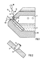
- a dosing furnace 1 with a vessel 12, in the liquid metal, for example aluminum, in a bath 2 is added.
- a riser pipe 3 is used, which through the wall 4th of the dosing furnace 1 is led to the outside.
- liquid metal is metered out.
- This can (according to a sensor device) through regulated pressurization inside the Vessel 12 is made to liquid metal through the To drive riser pipe 3 into a discharge pipe 13.
- the drain pipe 13 fills the molten metal, preferably Aluminum, for example in molds intended for this purpose. It is important that the amount of the vessel 12 expelled molten metal on the Volume of the molds is matched. For dosing it is necessary that the height of the metal column in the dosing furnace (or in the riser 3) exactly is detected, with a pneumatic for this detection Sensor device 6 is used.
- the pneumatic sensor device has a Tube-trained probe 5, which is preferably made of Ceramic exists, and that according to FIG. 2 in the wall 7 of the riser pipe 3 is used.
- a Tube-trained probe 5 which is preferably made of Ceramic exists, and that according to FIG. 2 in the wall 7 of the riser pipe 3 is used.
- This is for example in the wall 7 designed as a stepped bore Bore 8 provided, being in the bore part with a larger diameter the end of the probe 5 from pressed into the riser wall 7 and / or glued on the outside and the smaller diameter of the Stepped bore 8 approximately the inner diameter of the Tube 5 corresponds.
- the probe 5 is via a pressure measuring device 9 connected to a gas source 10.
- the gas source supplies gas at a certain pressure to the probe 5, which from its front end and through the hole 8 flows out.
- Pressure curve when approaching or increasing the Level is measured and there is a pressure threshold determined at which the level a predetermined assignment to the end of the probe 5.
- the pressure measuring device 9 then indicates a corresponding signal its output 11 to the further evaluation control / regulating devices.
- the adjustment of the pressure sensitivity is easy by adjusting the distance of the fixed Contact to the membrane with the help of a screw, which is provided with a scale. Depending on the position the screw is the fixed contact more or less far from the membrane contact, so that more or less pressure is applied to bring both contacts into contact.
- Probe 5 Since it, for example during a metering process from the Vessel 12 or riser pipe 3 and the discharge pipe 13 in a mold to close the bore 8 or Probe 5 can provide protection against clogging to provide these openings. This is first by a back pressure caused by the gas source given, which ensures when the bore 8 is closed, that the probe does not fill with molten metal. Moreover can with a suitable choice of materials Probe or the surrounding or enclosing components (Riser pipe, a section of the wall of the vessel) the accumulation of molten metal largely prevented become.
- Inner diameter of the probe 5 or as a connection hole 8 holes of less than 2 mm and a suitable material combination (ceramics for the parts of the metal which come into contact with the molten metal Probe 5 and the connection hole 8 containing Component, in this case the riser 3) is a Closure made difficult by molten metal. by virtue of that occurs with certain material pairings Surface tensions, for example between the ceramics and liquid aluminum, here is a closure even excluded. This is for the present Invention of vital importance, especially at On the basis of the fact that, for example in the form of casting, even the smallest voids are filled with molten metal become.
- In another embodiment of the present Invention can use multiple detection devices of a level of liquid metal in one Dosing furnace can be provided. Any of these devices each has its own probe with an outlet opening on. Are these outlet openings (regarding a resting level of the liquid metal) side by side, so in the case of a moving one Surface of the liquid metal (e.g. during a filling process in the dosing furnace) the level by suitable Averaging can be recorded. So that are possible Incorrect measurements due to a moving metal level largely excluded. However, it is also possible, the above-mentioned outlet openings one above the other to be arranged so as to determine the level within wide limits.
Abstract
Description
Die Erfindung betrifft einen Dosierofen mit einem Gefäß zur Aufnahme flüssigen Metalls und einer Vorrichtung zum Erfassen eines Pegels von flüssigem Metall in einem Gefäß.The invention relates to a dosing furnace with a Vessel for holding liquid metal and a device for detecting a level of liquid metal in a vessel.
Für das Dosieren von flüssigem Metall aus einem Dosierofen muß die in dem Dosierrohr ansteigende Metallsäule in ihrer Höhe erfaßt werden, da abhängig von dieser Erfassung die Dosiermenge berechnet wird. Es ist auch möglich, abhängig von der Erfassung der Höhe der Metallsäule unter Berücksichtigung anderer Parameter, zum Beispiel verschiedene Drücke, die Höhe des Flüssigkeitspegels im Ofen zu bestimmen. Aus der US 4 220 319 ist eine Sensoranordnung für Dosieröfen bekannt, bei der der Sensor aus einer senkrecht oder fast senkrecht zur Metalloberfläche stehenden Metallnadel besteht, die bei Kontaktierung mit der Flüssigmetalloberfläche ein Signal abgibt. Um den Verschleiß der Sensoranordnung zu verringern, wird die Metallnadel durch ein automatisiertes mechanisches System bei Kontaktierung von der Metalloberfläche weggeschwenkt. Diese bekannte Anordnung hat verschiedene Nachteile, insbesondere ist das mechanische Schwenksystem sehr aufwendig und teuer und trotz des Schwenkens ist der Verschleiß an der Metallnadel relativ groß. Die Nadel kann zunächst durch den Kontakt mit flüssigem Aluminium aufgrund chemischer Prozesse zersetzt werden. Außerdem kann das Meßergebnis durch Anlagerung von Aluminium bzw. Aluminiumoxid an der Nadel beeinträchtigt werden.For dosing liquid metal from a dosing furnace must the metal column rising in the metering tube be recorded in their amount, as dependent the dosing quantity is calculated from this recording. It is also possible depending on the capture of the Height of the metal column taking into account others Parameters, for example different pressures, the height of the liquid level in the oven. From the US 4,220,319 is a sensor arrangement for dosing furnaces known in which the sensor from a vertical or Metal needle almost perpendicular to the metal surface exists when contacting the liquid metal surface emits a signal. To wear to reduce the sensor arrangement, the metal needle through an automated mechanical system swung away from the metal surface when making contact. This known arrangement has several Disadvantages, especially the mechanical swivel system very complex and expensive and despite the pivoting the wear on the metal needle is relative large. The needle can initially be in contact with liquid aluminum decomposes due to chemical processes become. In addition, the measurement result can Accumulation of aluminum or aluminum oxide on the Needle will be affected.
In der Praxis ist durch den oben erläuterten Verschleiß der Metallnadel ein Schleifen, Reinigen oder der Austausch der Nadel notwendig, so daß die Abtastposition über einen längeren Zeitraum nicht gehalten werden kann. Ferner sind in der Praxis keine Justierhilfen bekannt, die eine reproduzierbare Abtastung ermöglichen. Insbesondere ist die Abtastposition im Verhältnis zur Auslaufkante des Dosierrohres bei Dosieröfen von besonderer Bedeutung. Die Nadel sollte für eine gut reproduzierbare Dosierung genau die Auslaufposition des Flüssigmetalls an der Auslaufkante des Dosierrohres erfassen (Nadel und Auslaufkante müssen auf gleicher Höhe sitzen). Die Erfassung wird aber in der Praxis nicht nur durch obengenannte Wartungs- und Instandsetzungsarbeiten an der Metallnadel verschoben sondern auch durch den Austausch des Dosierrohres, dessen Einbauhöhe direkt die Position der Auslaufkante bestimmt. Bedingt durch große fertigungstechnische Toleranzen im Feuerfestbereich kann der Einbau eines neuen Dosierrohres sowie einer neuen Dichtung etc. die Auslaufkante um bis zu 10 mm in senkrechter Höhe verschieben. In practice is due to the wear explained above grinding, cleaning or the metal needle the replacement of the needle is necessary so that the scanning position not held for a long period of time can be. Furthermore, in practice there are none Adjustment aids are known which have a reproducible scanning enable. In particular, the scanning position in relation to the outlet edge of the metering tube of particular importance for dosing furnaces. The needle should be accurate for a well reproducible dosage the outlet position of the liquid metal at the outlet edge of the dosing tube (needle and outlet edge must sit at the same height). The capture is in practice not only by the above Maintenance and repair work on the Metal needle shifted but also through the exchange of the metering tube, the installation height of which directly Position of the outlet edge determined. Due large manufacturing tolerances in the refractory sector can the installation of a new dosing tube as well a new seal, etc. the outlet edge by up to Move 10 mm vertically.
Bei Dosieröfen bewirkt eine Verschiebung der Abtastposition im Verhältnis zur Auslaufkante durch obengenannte Maßnahmen von zum Beispiel 5 mm eine Änderung des ausdosierten Metallgewichts von typisch 4 %. Gefordert wird eine Dosiergenauigkeit von 1 bis 2 %. Aufgrund des schlechten Zuganges und der Hitze, die in dem Abtastbereich herrscht, wird in der Praxis die Nadel nicht nachjustiert, sondern es werden die Druck- oder Zeitparameter der Dosierung bzw. bei uns das Dosiergewicht, welches bekanntlich nach der Integralmethode (Druck über Zeit) bestimmt wird, geändert, um die Verfälschung des Dosiergewichtes zu kompensieren. Dies hat den Nachteil, daß Gießer, die die Dosierparameter verschiedener Gießteile gespeichert haben, immer wieder Korrekturen dieser gespeicherten Werte vornehmen müssen, da die Abtastverhältnisse und damit die Dosierung eben nicht konstant bleiben.With dosing furnaces, the scanning position is shifted in relation to the outlet edge by the above Measures of, for example, 5 mm a change of the dosed metal weight of typically 4%. A dosing accuracy of 1 to 2% is required. Due to poor access and the heat that prevails in the scanning area, in practice Do not readjust the needle, but it will Pressure or time parameters of the dosage or with us the dosage weight, which is known according to the integral method (Pressure over time) is determined, changed, to compensate for the falsification of the dosing weight. This has the disadvantage that founders who die Dosing parameters of different castings saved have corrections to these saved again and again Must make values since the sampling ratios and so that the dosage does not remain constant.
Ein weiterer Nachteil der oben dargestellten Metallnadel ist (wegen des erforderlichen Kontaktes mit flüssiger Metallschmelze) prinzipbedingt. Eine sich auf der Oberfläche der Metallschmelze schon nach kürzester Zeit ausbildende Schicht, etwa von nicht leitendem Aluminiumoxid, muß von der Nadel erst durchbrochen werden. Es kommt infolge des Druckes der Nadel zu einem Ausbauchen der Metalloberfläche nach unten. Dies bewirkt zum einen ein ungenaues Meßergebnis (die Nadel gibt nach dem Durchbruch in einer zu tiefen Stellung ihr Signal ab, d.h. es wird weniger Metallschmelze angezeigt als eigentlich vorhanden). Außerdem kommt es nach dem Durchbrechen der Oxidoberfläche zu einem unnötig tiefen Eintauchen der Nadel in die flüssige Metallschmelze, sodaß der oben beschriebene Verschleiß der Metallnadel beschleunigt wird. Another disadvantage of the metal needle shown above is (because of the necessary contact with liquid metal melt) due to the principle. A yourself on the surface of the molten metal after a very short time Time-training layer, for example from not conductive aluminum oxide, must first of the needle be breached. It comes as a result of the pressure of the Needle to bulge the metal surface below. On the one hand, this causes an inaccurate measurement result (the needle admits in one after the breakthrough low signal, i.e. it gets less Molten metal appears as actually present). It also happens after breaking through the oxide surface for an unnecessarily deep immersion of the needle into the molten metal, so that the above described Accelerated wear of the metal needle becomes.
Aus der DE-OS 44 20 712 ist weiterhin eine Sensoranordnung zur Erfassung des Pegels von flüssigem Metall bekannt, bei der der Sensor aus elektrisch leitender Keramik besteht und in die Wand des Gefäßes oder eines Steigrohres bündig eingesetzt ist.DE-OS 44 20 712 is also a sensor arrangement to measure the level of liquid metal known in which the sensor made of electrically conductive There is ceramic and in the wall of the vessel or one Riser pipe is inserted flush.
Als maßgeblicher Stand der Technik wird die JP-A-05099726 angesehen. Diese offenbart ein in der Wandung einer mit Metallschmelze gefüllten Gießwanne angeordnetes, zu dem Inneren der Gießwanne hin offenes Rohr, wobei die Rohröffnung unterhalb der Oberkante der flüssigen Metallschmelze angeordnet ist. Aus dem Rohr wird Gas in die Schmelze eingeblasen. Der durch die Metallschmelze erzeugte Gegendruck (durch welchen auf die Füllhöhe der Metallschmelze geschlossen werden kann) in dem Rohr wird mit einer Druckmeßvorrichtung erfaßt.The relevant prior art is JP-A-05099726 considered. This reveals one in the wall a tundish filled with molten metal, open to the inside of the tundish Pipe with the pipe opening below the top edge the molten metal is arranged. From the Gas is blown into the melt into the tube. The through the metal melt generated back pressure (by which the level of the molten metal can be concluded can) in the tube with a pressure measuring device detected.
Für die Messung einer genauen Füllhöhe, welche die Erfordernisse eines Dosierofens erfüllen würde, wäre hier jedoch eine aufwendige Druckmeßvorrichtung notwendig, die zudem unter hohem Aufwand dauernd kalibriert werden müßte.For the measurement of an exact fill level, which the Would meet the requirements of a dosing furnace here, however, a complex pressure measuring device is necessary, which is also constantly calibrated at great expense should be.
Der Erfindung liegt die Aufgabe zugrunde, einen Dosierofen mit einem Gefäß zur Aufnahme flüssigen Metalls und einer Vorrichtung zum erfassen eines Pegels von flüssigem Metall in einem Gefäß zu schaffen, wobei die Vorrichtung einen vorbestimmten Pegel mit hoher Genauigkeit erfaßt.The invention has for its object a metering oven with a vessel for holding liquid metal and a device for detecting a level to create liquid metal in a vessel, being the device has a predetermined high level Accuracy recorded.
Diese Aufgabe wird erfindungsgemäß durch die kennzeichnenden Merkmale des Hauptanspruchs in Verbindung mit den Merkmalen des Oberbegriffs gelöst.This object is achieved by the characterizing Features of the main claim related solved with the features of the generic term.
Dadurch, daß die Druckmeßvorrichtung als Druckwellenschalter zur Erfassung einer beim Verschließen der Sondenöffnung durch flüssiges Metall auftretenden Druckansprechwelle innerhalb der Sonde und Abgabe eines entsprechenden Signals ausgeführt ist und die Sonde in die Wand eines in dem Gefäß vorgesehenen Steigrohrs fest eingesetzt ist, wird eine einfache Vorrichtung zur Erfassung des Pegels von flüssigem Metall zur Verfügung gestellt, die kostengünstig ist und trotzdem mit guter Sicherheit einen bestimmten Pegel erfaßt.The fact that the pressure measuring device as a pressure wave switch to capture a when closing the Probe opening occurring through liquid metal Pressure response wave within the probe and delivery of a corresponding signal is executed and the Probe into the wall of one provided in the vessel Riser is fixed, becomes a simple one Device for detecting the level of liquid Metal is provided that is inexpensive and still with certainty a certain one Level detected.
Im Gegensatz zu den einleitend genannten Verfahren, die auf elektrischer Kontaktierung basieren, ist bei der vorliegenden Vorrichtung zum Beispiel keine Erdung erforderlich. Das auf indirekter Messung mittels eines Gases basierende (die "Zwischenschaltung" des Gases minimiert den direkten Kontakt zwischen Sonde und Metallschmelze, außerdem zeigen dünne Ablagerungen auf der Sonde keine merkliche Beeinflussung der Strömungsverhältnisse des Gases), verschleißfreie und fest eingebaute Abtastsystem hat außerdem den Vorteil, daß die Abtastverhältnisse konstant bleiben. Einerseits ändert sich die Höhe der Abtastposition des Keramikröhrchens nicht (fest eingebaut), zum anderen nicht dessen Position relativ zur Auslaufkante (fest eingebaut). Das heißt, die Abtastverhältnisse bleiben konstant, selbst wenn das Dosierrohr mal höher oder tiefer im Dosierofen eingebaut ist. Außerdem ist eine Verfälschung von Meßwerten durch eine im Laufe der Zeit sich einstellende Änderung der elektrischen Leitfähigkeit (wie etwa bei dem oben erwähnten Sensor aus elektrisch leitender Keramik) ausgeschlossen.In contrast to the procedures mentioned in the introduction, which are based on electrical contacting is at for example, no grounding in the present device required. That on indirect measurement by means of a gas based (the "intermediary" of the Gases minimizes direct contact between the probe and molten metal, also show thin deposits no noticeable influence on the probe Flow conditions of the gas), wear-free and permanently installed scanning system also has the advantage that the sampling ratios remain constant. On the one hand, the height of the scanning position changes of the ceramic tube not (permanently installed), on the other not its position relative to the leading edge (permanently installed). That is, the sampling ratios remain constant even if the metering tube is higher or installed deeper in the dosing furnace. Moreover is a falsification of measured values by an im Over time, change in the electrical Conductivity (such as that mentioned above Sensor made of electrically conductive ceramic) excluded.
Durch die in den Unteransprüchen angegebenen Maßnahmen sind vorteilhafte Weiterbildungen und Verbesserungen möglich. Das Rohr bzw. die Sonde kann in die Wand oder das Steigrohr eines Dosierofens fest eingesetzt werden, wobei bei Passieren des Flüssigkeitspegels an dem Steigrohr das gewünschte Signal abgegeben wird. By the measures specified in the subclaims are advantageous further developments and improvements possible. The tube or the probe can be in the Wall or the riser pipe of a dosing furnace firmly inserted be, when passing the liquid level the desired signal is given on the riser becomes.
Vorzugsweise besteht die Sonde aus Keramik, dies führt dazu, daß die Möglichkeit von Metallanlagerungen an der Sonde minimiert wird (besonders bei der Werkstoffpaarung Keramik/Aluminium). Sollten sich dennoch dünne Ablagerungen (etwa aufgrund der Rauhigkeit der Sonde) einstellen, führt dies bei der erfindungsgemäßen Sonde nicht zu einer Funktionsbeeinträchtigung, während bei Meßsystemen, die auf elektrischer Kontaktierung basieren, bereits dünne Anlagerungen einen vollständigen Ausfall verursachen können.Preferably the probe is made of ceramic, this leads to the possibility of metal deposits on the probe is minimized (especially with the Material combination ceramic / aluminum). Should nevertheless thin deposits (e.g. due to the roughness of the probe), this leads to the invention Probe does not lead to a functional impairment, while with measuring systems based on electrical Contacting based, already thin deposits can cause a complete failure.
Es ist besonders vorteilhaft, die aus Keramik gefertigte Sonde mit einem Innendurchmesser von unter 2 mm zu versehen. Aufgrund der sich einstellenden Oberflächenspannungen, etwa von flüssigem Aluminium auf der Keramik, bleibt dann die Sonde (selbst bei ausbleibender Gasströmung) nicht durch flüssiges Aluminium verschlossen.It is particularly advantageous to use ceramic Probe with an inner diameter of less than 2 mm to provide. Because of the surface tensions that arise, of liquid aluminum on the Ceramic, the probe then remains (even if there is no Gas flow) not through liquid aluminum locked.
Eine weitere vorteilhafte Ausführungsform sieht vor, daß die Druckmeßvorrichtung einen in der Druckempfindlichkeit einstellbaren Druckwellenschalter zur Messung einer Druckansprechwelle des aus der Sonde ausströmenden Gases aufweist. Die Druckansprechwelle, die mit Erreichen (bzw. Verschluß) der Sonde durch einen Spiegel flüssigen Metalls entsteht, wird zum Beispiel als Signal zum Schließen eines Zuführventils in dem Dosierofen genutzt. Die Einstellbarkeit des Druckwellenschalters ermöglicht die einfache, auch während des Betriebs mögliche Abstimmung auf die Verhältnisse des jeweiligen Einbauorts.Another advantageous embodiment provides that the pressure measuring device one in the pressure sensitivity adjustable pressure wave switch for Measurement of a pressure response wave from the probe escaping gas. The pressure response wave, when the probe reaches (or closes) through a mirror of liquid metal is created Example as a signal to close a feed valve used in the dosing furnace. The adjustability of the Pressure wave switch enables easy, too possible adjustment to the conditions during operation of the respective installation location.
Eine vorteilhafte Weiterbildung sieht vor, daß der Dosierofen mehrere Vorrichtungen zum Erfassen eines Pegels von flüssigem Metall enthält, die jeweils eine Sonde mit einer Austrittsöffnung aufweisen. Liegen diese Austrittsöffnungen (bezüglich eines ruhenden Pegels des flüssigen Metalls) nebeneinander, so ist im Fall einer sich bewegenden Oberfläche des flüssigen Metalls der Pegel durch geeignete Mittelwertbildung der in den Sonden gemessenen Drücke erfaßbar, liegen diese Austrittsöffnungen übereinander, ist eine Füllstandsermittlung in weiten Grenzen möglich.An advantageous development provides that the Dosing furnace several devices for detecting a Level of liquid metal, each containing one Have a probe with an outlet opening. Lie these outlet openings (with respect to a resting one Level of the liquid metal) side by side, so is in the case of a moving surface of the liquid Metal level by appropriate averaging the pressures measured in the probes, are these outlet openings one above the other, is level determination possible within wide limits.
Ein Ausführungsbeispiel der Erfindung ist in der Zeichnung dargestellt und wird in der nachfolgenden Beschreibung näher erläutert. Es zeigen:
- Fig. 1
- schematisch einen Schnitt durch einen Dosierofen mit Steigrohr, und
- Fig. 2
- eine vergrößerte Teilansicht des Endes der in die steigrohrwand eingesetzten rohrförmigen Sonde.
- Fig. 1
- schematically shows a section through a dosing furnace with a riser, and
- Fig. 2
- an enlarged partial view of the end of the tubular probe inserted into the riser wall.
Fig. 1 zeigt einen Dosierofen 1 mit einem Gefäß 12,
in dem flüssiges Metall, zum Beispiel Aluminium, in
einem Bad 2 aufgenommen ist. In den Dosierofen 1 ist
ein Steigrohr 3 eingesetzt, das durch die Wandung 4
des Dosierofens 1 nach außen geführt ist. Über das
Steigrohr 3 wird flüssiges Metall ausdosiert. Dies
kann etwa (nach Maßgabe einer Sensorvorrichtung)
durch geregelte Druckbeaufschlagung im Inneren des
Gefäßes 12 erfolgen, um flüssiges Metall durch das
Steigrohr 3 in ein Abführrohr 13 zu treiben. Das Abführrohr
13 füllt die Metallschmelze, vorzugsweise
Aluminium, zum Beispiel in dafür vorgesehene Gußformen.
Hierbei ist es wichtig, daß die Menge der aus
dem Gefäß 12 herausgetriebenen Metallschmelze auf das
Volumen der Gußformen abgestimmt ist. Für das Ausdosieren
ist es notwendig, daß die Höhe der Metallsäule
in dem Dosierofen (bzw. in dem Steigrohr 3) genau
erfaßt wird, wobei für diese Erfassung eine pneumatische
Sensorvorrichtung 6 verwendet wird.1 shows a dosing furnace 1 with a vessel 12,
in the liquid metal, for example aluminum, in
a bath 2 is added. In the dosing oven 1 is
a riser pipe 3 is used, which through the wall 4th
of the dosing furnace 1 is led to the outside. About the
Riser pipe 3, liquid metal is metered out. This
can (according to a sensor device)
through regulated pressurization inside the
Vessel 12 is made to liquid metal through the
To drive riser pipe 3 into a
Die pneumatische Sensorvorrichtung weist eine als
Rohr ausgebildete Sonde 5 auf, die vorzugsweise aus
Keramik besteht, und die gemäß Fig. 2 in die Wand 7
des Steigrohres 3 eingesetzt ist. Dazu ist beispielsweise
in der Wand 7 eine als Stufenbohrung ausgeführte
Bohrung 8 vorgesehen, wobei in dem Bohrungsteil
mit größerem Durchmesser das Ende der Sonde 5 von
außen in die Steigrohrwand 7 eingepreßt und/oder eingeklebt
ist, und wobei der kleinere Durchmesser der
Stufenbohrung 8 in etwa dem Innendurchmesser des
Rohres 5 entspricht. Die Sonde 5 ist über eine Druckmeßvorrichtung
9 mit einer Gasquelle 10 verbunden.
Die Gasquelle liefert Gas mit einem bestimmten Druck
an die Sonde 5, das aus ihrem vorderen Ende und durch
die Bohrung 8 ausströmt. Wenn sich der Metallspiegel
in dem Steigrohr dem Ende der Sonde nähert, verändern
sich die Strömungsverhältnisse am Ende der Sonde und
es tritt eine Druckänderung in der Sonde auf. Diese
Druckänderung wird von der Druckmeßvorrichtung 9 bestimmt.
Es handelt sich hierbei also um ein mittelbares
Verfahren zur Messung des Pegelstandes, da der
Pegelstand nicht direkt (etwa über Berührung mit einem
dafür vorgesehenen Kontaktelement) erfolgen muß.
Statt dessen wird der Einfluß eines zu messenden Metallpegels
auf gegebene Strömungsverhältnisse (eines
Gases, das aus einer Gasquelle mit definiertem Druck
ausströmt) ermittelt. Dieser Einfluß kann über eine
Druckänderung des ausströmenden Gases in der Sonde 5
festgestellt werden. Über diese Druckänderung sind
also Aussagen über den Pegel des flüssigen Metalls
möglich. Eine besonders deutlich meßbare Druckänderung
tritt auf, wenn das offene Ende der Sonde 5
(bzw. die Bohrung 8) durch das flüssige Metall verschlossen
wird.The pneumatic sensor device has a
Tube-trained
Um den Pegel des flüssigen Metalls genau erfassen zu
können, wird vor den eigentlichen Messungen die
Druckkurve bei der Annäherung bzw. beim Ansteigen des
Pegels gemessen und es wird ein Druckschwellenwert
bestimmt, bei dem der Pegel eine vorbestimmte Zuordnung
zu dem Ende der Sonde 5 aufweist. Die Druckmeßvorrichtung
9 gibt dann ein entsprechendes Signal an
ihrem Ausgang 11 zu den weiteren Auswerte-Steuer/Regeleinrichtungen. To accurately grasp the level of the liquid metal
before the actual measurements
Pressure curve when approaching or increasing the
Level is measured and there is a pressure threshold
determined at which the level a predetermined assignment
to the end of the
Es wird ein sogenannter Druckwellenschalter
verwendet, dessen Einstellbereich etwa
zwischen 0,5 und 5 mbar liegt. Diese Schalter besitzen
im Innern eine Membran, auf der ein Kontakt angebracht
ist. Die eine Seite der Membran steht mit dem
Umgebungsdruck in Verbindung, die andere Seite ist
mit dem Abtaströhrchen oder Sonde 5 verbunden. Wird
nun das Abtaströhrchen 5 mit einer Flüssigkeit verschlossen,
steigt der Druck im Abtaströhrchen 5 und
damit auf einer Seite der Membran und diese wird gegen
einen feststehenden Kontakt gedrückt, so daß der
Kontakt auf der Membran mit dem feststehenden in Berührung
kommt. Dadurch wird ein Stromfluß bei Erreichen
der Druckansprechschwelle ermöglicht.It becomes a so-called pressure wave switch
used, the setting range about
is between 0.5 and 5 mbar. Own these switches
inside a membrane on which a contact is attached
is. One side of the membrane stands with the
Ambient pressure, which is the other side
connected to the sampling tube or
Die Verstellung der Druckempfindlichkeit erfolgt einfach durch das Verstellen des Abstandes des feststehenden Kontaktes zur Membran mit Hilfe einer Schraube, die mit einer Skala versehen ist. Je nach Stellung der Schraube ist der feststehende Kontakt mehr oder weniger weit von dem Membrankontakt entfernt, so daß auch mehr oder weniger Druck aufgewendet werden muß, um beide Kontakte in Berührung zu bringen.The adjustment of the pressure sensitivity is easy by adjusting the distance of the fixed Contact to the membrane with the help of a screw, which is provided with a scale. Depending on the position the screw is the fixed contact more or less far from the membrane contact, so that more or less pressure is applied to bring both contacts into contact.
Da es, etwa während eines Ausdosiervorganges aus dem
Gefäß 12 bzw. Steigrohr 3 und dem Abführrohr 13 in
eine Gußform zum Verschließen der Bohrung 8 bzw. der
Sonde 5 kommen kann, ist ein Schutz gegen Verstopfen
dieser Öffnungen vorzusehen. Dieser ist zunächst
durch einen von der Gasquelle verursachten Staudruck
gegeben, der bei Verschluß der Bohrung 8 dafür sorgt,
daß die Sonde nicht mit Metallschmelze volläuft. Außerdem
kann bei geeigneter Wahl der Materialien der
Sonde bzw. der sie umgebenden bzw. einfassenden Bauteile
(Steigrohr, ein Abschnitt der Wand des Gefäßes)
die Anlagerung von Metallschmelze weitgehend verhindert
werden. Mit der erfindungsgemäßen Wahl eines
Innendurchmessers der Sonde 5 bzw. der als Anschlußbohrung
8 ausgeführten Bohrung von unter 2 mm und
einer geeigneten Werkstoffpaarung (Keramik für die
mit der Metallschmelze in Kontakt tretenden Teile der
Sonde 5 und des die Anschlußbohrung 8 enthaltenden
Bauteils, in diesem Fall das Steigrohr 3) wird ein
Verschluß durch Metallschmelze erschwert. Aufgrund
der sich bei bestimmten Werkstoffpaarungen einstellenden
Oberflächenspannungen, etwa zwischen der Keramik
und flüssigem Aluminium, ist hier ein Verschluß
sogar ausgeschlossen. Dies ist für die vorliegende
Erfindung von entscheidender Bedeutung, besonders bei
Zugrundelegung der Tatsache, daß, etwa im Formguß,
auch kleinste Hohlräume mit Metallschmelze ausgefüllt
werden.Since it, for example during a metering process from the
Vessel 12 or riser pipe 3 and the
In einer anderen Ausführungsform der vorliegenden Erfindung können mehrere Vorrichtungen zum Erfassen eines Pegels von flüssigem Metall in einem einzigen Dosierofen vorgesehen sein. Jede dieser Vorrichtungen weist jeweils eine eigene Sonde mit einer Austrittsöffnung auf. Liegen diese Austrittsöffnungen (bezüglich eines ruhenden Pegels des flüssigen Metalls) nebeneinander, so ist im Fall einer sich bewegenden Oberfläche des flüssigen Metalls (etwa bei einem Einfüllvorgang in den Dosierofen) der Pegel durch geeignete Mittelwertbildung erfaßbar. Damit sind mögliche Fehlmessungen infolge eines sich bewegenden Metallpegels weitgehend ausgeschlossen. Es ist jedoch auch möglich, die obengenannten Austrittsöffnungen übereinander anzuordnen, um so eine Füllstandsermittlung in weiten Grenzen zu ermöglichen.In another embodiment of the present Invention can use multiple detection devices of a level of liquid metal in one Dosing furnace can be provided. Any of these devices each has its own probe with an outlet opening on. Are these outlet openings (regarding a resting level of the liquid metal) side by side, so in the case of a moving one Surface of the liquid metal (e.g. during a filling process in the dosing furnace) the level by suitable Averaging can be recorded. So that are possible Incorrect measurements due to a moving metal level largely excluded. However, it is also possible, the above-mentioned outlet openings one above the other to be arranged so as to determine the level within wide limits.
Claims (7)
- Metering oven (1) comprising a vessel (12) for holding liquid metal and a device for detecting a liquid metal level in a vessel, and a tubular probe (5) is connected to a gas source (10) for discharging a gas from the gas source through the probe and its outlet opening, and a pressure measuring device (9) is provided for detecting a pressure condition within the probe (5) in dependence of a counter-pressure caused by a liquid metal level, characterised in that the pressure measuring device (9) is designed as a pressure-wave switch for detection of a pressure response wave which develops when the probe opening is closed by liquid metal and which gives a respective signal, and the probe (5) is firmly inserted into the wall of a rise pipe (3) provided in the vessel (12).
- Metering oven according to Claim 1, characterised in that the probe and/or the rise pipe (3) are made of ceramics or substantially of ceramics.
- Metering oven according to one of Claims 1 or 2, characterised in that the probe (5) is pressed and/or glued into a bore (8).
- Metering oven according to Claim 2 and/or Claim 3, characterised in that the outlet opening of the probe (5) and/or the bore (8) have an inside diameter of less than 5 mm, preferably less than 2 mm.
- Metering oven according to one of the above claims, characterised in that the pressure-wave switch is adjustable as regards its pressure sensitivity.
- Metering oven according to one of the above claims, characterised in that a first and a second device for detection of a metal level is provided which comprise a first and a second probe with a first and a second outlet opening.
- Metering oven according to Claim 6, characterised in that the first outlet opening lies relative to an idle level of liquid metal above or alongside the second outlet opening.
Applications Claiming Priority (3)
| Application Number | Priority Date | Filing Date | Title |
|---|---|---|---|
| DE19647713 | 1996-11-11 | ||
| DE19647713A DE19647713C2 (en) | 1996-11-11 | 1996-11-11 | Device for detecting a level of liquid metal |
| PCT/DE1997/002663 WO1998020996A1 (en) | 1996-11-11 | 1997-11-10 | Metering oven |
Publications (2)
| Publication Number | Publication Date |
|---|---|
| EP0946314A1 EP0946314A1 (en) | 1999-10-06 |
| EP0946314B1 true EP0946314B1 (en) | 2003-06-25 |
Family
ID=7812052
Family Applications (1)
| Application Number | Title | Priority Date | Filing Date |
|---|---|---|---|
| EP97951076A Expired - Lifetime EP0946314B1 (en) | 1996-11-11 | 1997-11-10 | Metering oven |
Country Status (9)
| Country | Link |
|---|---|
| US (1) | US6303073B1 (en) |
| EP (1) | EP0946314B1 (en) |
| JP (1) | JP4327908B2 (en) |
| AT (1) | ATE243580T1 (en) |
| BR (1) | BR9713002A (en) |
| CA (1) | CA2271207C (en) |
| DE (2) | DE19647713C2 (en) |
| ES (1) | ES2201336T3 (en) |
| WO (1) | WO1998020996A1 (en) |
Cited By (2)
| Publication number | Priority date | Publication date | Assignee | Title |
|---|---|---|---|---|
| EP2283950A1 (en) | 2009-08-12 | 2011-02-16 | Strikowestofen Gmbh | Method and device for dosing molten metal |
| EP3189913A1 (en) | 2016-01-08 | 2017-07-12 | StrikoWestofen GmbH | Method and device for dosing molten material |
Families Citing this family (2)
| Publication number | Priority date | Publication date | Assignee | Title |
|---|---|---|---|---|
| EP3311937A1 (en) * | 2016-10-21 | 2018-04-25 | StrikoWestofen GmbH | Riser tube arrangement for detecting molten metal level |
| CN109959421B (en) * | 2017-12-25 | 2023-04-07 | 博世热力技术(上海)有限公司 | Water level detection device |
Family Cites Families (7)
| Publication number | Priority date | Publication date | Assignee | Title |
|---|---|---|---|---|
| DD135097B1 (en) * | 1978-03-27 | 1980-08-27 | Lothar Schlaupitz | DEVICE FOR MONITORING AND CONTROLLING THE LEVEL IN LIQUID CONTAINERS |
| GB1585151A (en) * | 1978-05-31 | 1981-02-25 | Westofen Gmbh | Ovens |
| JPH01245120A (en) * | 1988-02-09 | 1989-09-29 | Westofen Gmbh | Method and apparatus for measuring fluid medium |
| JPH0599726A (en) * | 1991-05-30 | 1993-04-23 | Kawasaki Steel Corp | Method for detecting level of molten metal in tundish |
| JPH06587A (en) * | 1992-06-23 | 1994-01-11 | Nippon Steel Corp | Method for measuring and controlling boundary layer level of molten metal in continuous casting for double-layer cast slab |
| DE4318252A1 (en) * | 1993-06-02 | 1994-12-08 | Friedhelm Prof Dr Ing Kahn | Method and device for casting components |
| DE4420712C2 (en) * | 1994-06-14 | 1998-07-16 | Strikfeldt & Koch | Device for detecting a level of liquid metal |
-
1996
- 1996-11-11 DE DE19647713A patent/DE19647713C2/en not_active Expired - Lifetime
-
1997
- 1997-11-10 US US09/297,992 patent/US6303073B1/en not_active Expired - Lifetime
- 1997-11-10 AT AT97951076T patent/ATE243580T1/en not_active IP Right Cessation
- 1997-11-10 EP EP97951076A patent/EP0946314B1/en not_active Expired - Lifetime
- 1997-11-10 WO PCT/DE1997/002663 patent/WO1998020996A1/en active IP Right Grant
- 1997-11-10 BR BR9713002-8A patent/BR9713002A/en not_active IP Right Cessation
- 1997-11-10 ES ES97951076T patent/ES2201336T3/en not_active Expired - Lifetime
- 1997-11-10 CA CA002271207A patent/CA2271207C/en not_active Expired - Fee Related
- 1997-11-10 DE DE59710352T patent/DE59710352D1/en not_active Expired - Lifetime
- 1997-11-10 JP JP52205298A patent/JP4327908B2/en not_active Expired - Lifetime
Cited By (4)
| Publication number | Priority date | Publication date | Assignee | Title |
|---|---|---|---|---|
| EP2283950A1 (en) | 2009-08-12 | 2011-02-16 | Strikowestofen Gmbh | Method and device for dosing molten metal |
| DE102009037368A1 (en) | 2009-08-12 | 2011-02-17 | Strikowestofen Gmbh | Method and apparatus for dosing molten metal |
| EP3189913A1 (en) | 2016-01-08 | 2017-07-12 | StrikoWestofen GmbH | Method and device for dosing molten material |
| WO2017118722A1 (en) | 2016-01-08 | 2017-07-13 | Strikowestofen Gmbh | Device and method for metering molten material |
Also Published As
| Publication number | Publication date |
|---|---|
| AU733931B2 (en) | 2001-05-31 |
| AU5476098A (en) | 1998-06-03 |
| CA2271207A1 (en) | 1998-05-22 |
| BR9713002A (en) | 2000-01-25 |
| DE19647713C2 (en) | 2000-01-05 |
| EP0946314A1 (en) | 1999-10-06 |
| WO1998020996A1 (en) | 1998-05-22 |
| CA2271207C (en) | 2006-09-12 |
| JP4327908B2 (en) | 2009-09-09 |
| ES2201336T3 (en) | 2004-03-16 |
| US6303073B1 (en) | 2001-10-16 |
| DE19647713A1 (en) | 1998-05-14 |
| JP2001504218A (en) | 2001-03-27 |
| DE59710352D1 (en) | 2003-07-31 |
| ATE243580T1 (en) | 2003-07-15 |
Similar Documents
| Publication | Publication Date | Title |
|---|---|---|
| EP2937692A2 (en) | Oil quality sensor and deep frying device with such an oil quality sensor | |
| DE2433060C2 (en) | A method of pouring predetermined quantities of molten metal and apparatus for carrying out this method | |
| DE3416127A1 (en) | DEVICE AND METHOD FOR ADJUSTING VOLUMETRIC CAVES FOR GRAVIMETRIC DOSING OF LIQUIDS | |
| EP0946314B1 (en) | Metering oven | |
| EP1832362B1 (en) | Vacuum pressure casting installation and method for using the same | |
| DE3040762A1 (en) | METHOD AND DEVICE FOR ADJUSTING THE MASS OF LOTS OF THERMOPLASTIC MATERIALS | |
| EP1881316A2 (en) | Method and device for determining the density of a fluid | |
| DE102012019743B3 (en) | Precipitation Sensor | |
| DE4402463C2 (en) | Device for discontinuous detection of the thickness of a layer on a molten metal | |
| DE102009014311A1 (en) | Method for monitoring and / or controlling and / or regulating functions of and in injection molding machines | |
| DE3346650A1 (en) | Process and apparatus for the determination and control of a level of a metal melt | |
| DE102018105900B4 (en) | Wave soldering machine and method for determining the height of the soldering wave | |
| DE2634971A1 (en) | DEVICE FOR THE CONTINUOUS DETERMINATION OF THE CARBON DIOXIDE CONTENT OF A LIQUID THROUGH A LINE, IN PARTICULAR A BEVERAGE | |
| EP2018540A1 (en) | Immersion probe for lips apparatuses | |
| DE19943861A1 (en) | Wood metal heating device which allows Noack liquid measurement of a liquid sample of a petroleum product, mainly a lubricating oil, and method using this device | |
| DE19751377C2 (en) | Tester | |
| EP1936366B1 (en) | Method and apparatus for monitoring an electrochemical half-cell | |
| EP0602629A1 (en) | Watertap, in particular water mixer-tap with flow measuring device | |
| EP1942344B1 (en) | Method for inspecting the behaviour of a material in a construction material | |
| WO2019243185A1 (en) | Method for the online sensing of the rheology of thermoplastic and/or elastomer material for the production of injection-moulded parts | |
| DE3146360C2 (en) | Device for level control of the bath level in a continuous casting mold | |
| DE1598471C3 (en) | Method and device for the production of a sample of a certain shape and density of a finely divided material | |
| DE102022214165B3 (en) | Coffee preparation device and method for determining a pressing force and a brewing pressure with such a coffee preparation device | |
| EP1602901B1 (en) | Method and device for measuring the liquid level in a metal melt | |
| DE7805911U1 (en) | MEASURING DEVICE FOR DETERMINING THE CHILL INNER WALL WEAR IN STEEL OR METAL CONTINUOUS CASTING PLANTS |
Legal Events
| Date | Code | Title | Description |
|---|---|---|---|
| PUAI | Public reference made under article 153(3) epc to a published international application that has entered the european phase |
Free format text: ORIGINAL CODE: 0009012 |
|
| 17P | Request for examination filed |
Effective date: 19990505 |
|
| AK | Designated contracting states |
Kind code of ref document: A1 Designated state(s): AT CH DE ES FR GB IT LI NL |
|
| 17Q | First examination report despatched |
Effective date: 20000706 |
|
| GRAG | Despatch of communication of intention to grant |
Free format text: ORIGINAL CODE: EPIDOS AGRA |
|
| GRAG | Despatch of communication of intention to grant |
Free format text: ORIGINAL CODE: EPIDOS AGRA |
|
| GRAH | Despatch of communication of intention to grant a patent |
Free format text: ORIGINAL CODE: EPIDOS IGRA |
|
| GRAH | Despatch of communication of intention to grant a patent |
Free format text: ORIGINAL CODE: EPIDOS IGRA |
|
| GRAA | (expected) grant |
Free format text: ORIGINAL CODE: 0009210 |
|
| RAP1 | Party data changed (applicant data changed or rights of an application transferred) |
Owner name: STRIKOWESTOFEN GMBH |
|
| AK | Designated contracting states |
Designated state(s): AT CH DE ES FR GB IT LI NL |
|
| REG | Reference to a national code |
Ref country code: GB Ref legal event code: FG4D Free format text: NOT ENGLISH |
|
| REG | Reference to a national code |
Ref country code: CH Ref legal event code: EP |
|
| GBT | Gb: translation of ep patent filed (gb section 77(6)(a)/1977) | ||
| REF | Corresponds to: |
Ref document number: 59710352 Country of ref document: DE Date of ref document: 20030731 Kind code of ref document: P |
|
| REG | Reference to a national code |
Ref country code: CH Ref legal event code: NV Representative=s name: TROESCH SCHEIDEGGER WERNER AG |
|
| REG | Reference to a national code |
Ref country code: ES Ref legal event code: FG2A Ref document number: 2201336 Country of ref document: ES Kind code of ref document: T3 |
|
| ET | Fr: translation filed | ||
| PLBE | No opposition filed within time limit |
Free format text: ORIGINAL CODE: 0009261 |
|
| STAA | Information on the status of an ep patent application or granted ep patent |
Free format text: STATUS: NO OPPOSITION FILED WITHIN TIME LIMIT |
|
| 26N | No opposition filed |
Effective date: 20040326 |
|
| PGFP | Annual fee paid to national office [announced via postgrant information from national office to epo] |
Ref country code: GB Payment date: 20071127 Year of fee payment: 11 |
|
| PGFP | Annual fee paid to national office [announced via postgrant information from national office to epo] |
Ref country code: NL Payment date: 20081113 Year of fee payment: 12 Ref country code: CH Payment date: 20081114 Year of fee payment: 12 |
|
| PGFP | Annual fee paid to national office [announced via postgrant information from national office to epo] |
Ref country code: AT Payment date: 20081114 Year of fee payment: 12 |
|
| GBPC | Gb: european patent ceased through non-payment of renewal fee |
Effective date: 20081110 |
|
| PG25 | Lapsed in a contracting state [announced via postgrant information from national office to epo] |
Ref country code: GB Free format text: LAPSE BECAUSE OF NON-PAYMENT OF DUE FEES Effective date: 20081110 |
|
| REG | Reference to a national code |
Ref country code: NL Ref legal event code: V1 Effective date: 20100601 |
|
| REG | Reference to a national code |
Ref country code: CH Ref legal event code: PL |
|
| PG25 | Lapsed in a contracting state [announced via postgrant information from national office to epo] |
Ref country code: AT Free format text: LAPSE BECAUSE OF NON-PAYMENT OF DUE FEES Effective date: 20091110 |
|
| PG25 | Lapsed in a contracting state [announced via postgrant information from national office to epo] |
Ref country code: NL Free format text: LAPSE BECAUSE OF NON-PAYMENT OF DUE FEES Effective date: 20100601 Ref country code: LI Free format text: LAPSE BECAUSE OF NON-PAYMENT OF DUE FEES Effective date: 20091130 Ref country code: CH Free format text: LAPSE BECAUSE OF NON-PAYMENT OF DUE FEES Effective date: 20091130 |
|
| REG | Reference to a national code |
Ref country code: FR Ref legal event code: PLFP Year of fee payment: 19 |
|
| REG | Reference to a national code |
Ref country code: FR Ref legal event code: PLFP Year of fee payment: 20 |
|
| PGFP | Annual fee paid to national office [announced via postgrant information from national office to epo] |
Ref country code: FR Payment date: 20161118 Year of fee payment: 20 Ref country code: DE Payment date: 20161129 Year of fee payment: 20 |
|
| PGFP | Annual fee paid to national office [announced via postgrant information from national office to epo] |
Ref country code: ES Payment date: 20161114 Year of fee payment: 20 Ref country code: IT Payment date: 20161123 Year of fee payment: 20 |
|
| REG | Reference to a national code |
Ref country code: DE Ref legal event code: R071 Ref document number: 59710352 Country of ref document: DE |
|
| REG | Reference to a national code |
Ref country code: ES Ref legal event code: FD2A Effective date: 20180508 |
|
| PG25 | Lapsed in a contracting state [announced via postgrant information from national office to epo] |
Ref country code: ES Free format text: LAPSE BECAUSE OF EXPIRATION OF PROTECTION Effective date: 20171111 |