EP0602629A1 - Watertap, in particular water mixer-tap with flow measuring device - Google Patents
Watertap, in particular water mixer-tap with flow measuring device Download PDFInfo
- Publication number
- EP0602629A1 EP0602629A1 EP93120233A EP93120233A EP0602629A1 EP 0602629 A1 EP0602629 A1 EP 0602629A1 EP 93120233 A EP93120233 A EP 93120233A EP 93120233 A EP93120233 A EP 93120233A EP 0602629 A1 EP0602629 A1 EP 0602629A1
- Authority
- EP
- European Patent Office
- Prior art keywords
- water
- fitting according
- display
- flow rate
- measuring channel
- Prior art date
- Legal status (The legal status is an assumption and is not a legal conclusion. Google has not performed a legal analysis and makes no representation as to the accuracy of the status listed.)
- Granted
Links
Images


Classifications
-
- G—PHYSICS
- G01—MEASURING; TESTING
- G01F—MEASURING VOLUME, VOLUME FLOW, MASS FLOW OR LIQUID LEVEL; METERING BY VOLUME
- G01F5/00—Measuring a proportion of the volume flow
-
- E—FIXED CONSTRUCTIONS
- E03—WATER SUPPLY; SEWERAGE
- E03C—DOMESTIC PLUMBING INSTALLATIONS FOR FRESH WATER OR WASTE WATER; SINKS
- E03C1/00—Domestic plumbing installations for fresh water or waste water; Sinks
- E03C1/02—Plumbing installations for fresh water
- E03C1/04—Water-basin installations specially adapted to wash-basins or baths
- E03C1/0412—Constructional or functional features of the faucet handle
Landscapes
- Physics & Mathematics (AREA)
- Fluid Mechanics (AREA)
- General Physics & Mathematics (AREA)
- Health & Medical Sciences (AREA)
- Life Sciences & Earth Sciences (AREA)
- Engineering & Computer Science (AREA)
- Hydrology & Water Resources (AREA)
- Public Health (AREA)
- Water Supply & Treatment (AREA)
- Measuring Volume Flow (AREA)
- Domestic Plumbing Installations (AREA)
- Cookers (AREA)
- Food-Manufacturing Devices (AREA)
Abstract
Description
Die Erfindung betrifft eine Wasserarmatur, insbesondere Wassermischarmatur mit den Merkmalen des Oberbegriffes des Schutzanspruches 1.The invention relates to a water fitting, in particular a water mixer fitting with the features of the preamble of
Bei einer Vielzahl von Tätigkeiten, z. B. im Haushalt, d. h. bei der Zubereitung von z. B. Fertiggerichten wie Trockensuppen, Kuchen, Desserts, Soßen in Pulverform usw. ist es wichtig, die erfoderliche Wassermenge genau dosieren zu können.In a variety of activities, e.g. B. in the household, d. H. in the preparation of z. B. Ready meals such as dry soups, cakes, desserts, sauces in powder form, etc., it is important to be able to precisely dose the required amount of water.
Dazu wird heute zunächst einmal eine bestimmte Wassermenge in ein Meßbehältnis gefüllt, um dann die Wassermenge der Benutzung zuzuführen.For this purpose, a certain amount of water is first poured into a measuring container in order to then supply the amount of water for use.
Eine derartige Vorgehensweise erfordert zum einen die Bereitstellung eines entsprechenden Meßbehältnisses und zum anderen einen erheblichen Zeitaufwand, wobei noch hinzu kommt, daß häufig zunächst einmal eine zu große Wassermenge in das Meßbehältnis hineingefüllt wird, um dann die überschüssige Menge ohne weitere sinnvolle Verwendung in den Abfluß zu schütten.Such a procedure requires, on the one hand, the provision of a corresponding measuring container and, on the other hand, a considerable amount of time, with the fact that often too much water is first of all poured into the measuring container and then the excess quantity is discharged into the drain without any further meaningful use pour.
Dadurch wird zum einen bei Summierung dieser Vorgänge aller Haushalte eine erhebliche Menge aufbereiteten Wassers ungenutzt wieder entsorgt, so daß ein erheblicher volkswirtschaftlicher Schaden entsteht. Hinzu kommt, daß es sich hierbei häufig um erwärmtes Wasser handelt, so daß auch unter dem Gesichtspunkt der Energieersparnis erhebliche unnötige Kosten verursacht werden. Diese Methode ist daher sowohl aus ökologischer als auch ökonomischer Sicht wenig sinnvoll.As a result, when all these processes are summed up, a considerable amount of treated water is disposed of again unused, so that considerable economic damage occurs. In addition, this is often heated water, so that considerable unnecessary costs are incurred from the point of view of energy savings. This method therefore makes little sense from both an ecological and an economic point of view.
Diesem Problem wird bei einer Vielzahl von Wasserarmaturen dadurch versucht zu begegnen, daß die austretende Wassermenge erfaßt und dosiert werden soll.In a large number of water fittings, this problem is attempted to be countered by recording and metering the amount of water escaping.
Hierzu wird zum einen als Parameter zur Berechnung der Wassermenge der Zeitfaktor und zum anderen der anstehende Wasserdruck verwandt, um sodann die durchfließende Wassermenge innerhalb eines bestimmten Zeitraumes festzulegen.For this purpose, the time factor is used on the one hand as a parameter for calculating the amount of water and on the other hand the pending water pressure, in order to then determine the amount of water flowing through within a certain period of time.
Diese Methode hat sich jedoch in der Praxis als nicht vorteilhaft erwiesen, da zum einen ein reltiv hoher technischer Aufwand vonnöten ist und zum anderen entsprechende Druckschwankungen in der Praxis die Regel sind, die das Gerät nicht erfassen kann oder nur mit hohem technischen Aufwand und zum anderen der auftretende Druck und der Zeitfaktor nicht ausreicht, um eine genaue Dosierung bzw. Messung der gegebenen Wassermenge vorzunehmen, da als weiterer Parameter z. B. die Öffnung des Verschlußventiles hinzukommt.However, this method has not proven to be advantageous in practice, since on the one hand a relatively high technical effort is required and on the other hand corresponding pressure fluctuations are the rule in practice that the device cannot record or only with high technical effort and on the other hand the pressure occurring and the time factor are not sufficient to carry out an exact metering or measurement of the given amount of water, because as a further parameter z. B. the opening of the closure valve is added.
Um mit den herkömmlichen Methoden die durch eine Wasserarmatur abgegebene Wassermenge zu messen, ist somit ein erheblicher konstruktiver und damit finanzieller Aufwand vonnöten, so daß in der Praxis derart ausgerüstete Armaturen für den täglichen Gebrauch zu kostspielig sind.In order to measure the amount of water delivered by a water fitting with the conventional methods, a considerable constructive and thus financial outlay is required, so that fittings equipped in this way are too expensive for daily use in practice.
Der Erfindung liegt daher die Aufgabe zugrunde, eine Wasserarmatur, insbesondere Wassermischarmatur bereit zu stellen, bei der die abgegebene Wassermenge während des Wasserflusses kontinuierlich angezeigt wird, und dies bei geringem technischen Aufwand und damit geringen Kosten bei gleichzeitig hoher Meßgenauigkeit.The invention is therefore based on the object of providing a water fitting, in particular a water mixer fitting, in which the amount of water released is continuously displayed during the flow of water, and this with little technical outlay and thus low costs and at the same time high measuring accuracy.
Diese Aufgabe wird bei einer Wasserarmatur, insbesondere Wassermischarmatur der eingangs genannten Gattung mit den Merkmalen des kennzeichnenden Teils des Schutzanspruches 1 gelöst. Weitere vorteilhafte Ausgestaltungen der Erfindung sind Gegenstand der Ansprüche 2 bis 19.This object is achieved in a water fitting, in particular a water mixing fitting of the type mentioned at the outset, with the features of the characterizing part of the
Dadurch, daß ein wenigstens zeitweise von Wasser durchströmter mit einer die Durchflußmenge erfaßenden Einrichtung versehener Kanal vorgesehen ist und daß wenigstens eine Einrichtung zur Anzeige der Wasserdurchflußmenge vorgesehen ist, wird erreicht, daß eine Messung des durch die Wasserarmatur abgegebenen Wassers kontinuierlich, d. h. während der Abgabe möglich ist.Characterized in that a channel, at least temporarily flowed through by water and provided with a device that measures the flow rate, is provided and that at least one device is provided to display the water flow rate, it is achieved that a measurement of the water dispensed by the water fitting is possible continuously, ie during dispensing.
Ist die Kanalquerschnittsgröße proportional zur Querschnittsgröße des Querschnittes der zugeordneten Wasserführungseinrichtung ausgebildet, so ermöglicht dies eine kontinuierliche Messung des durch die Wasserarmatur abgegebenen Wassers, ohne daß dies die maximale Durchflußmenge, d. h. die maximale Abgabemöglichkeit der Wasserarmatur negativ beeinflußt und ohne daß ein hoher konstruktiver Aufwand vonnöten ist. Es wird vielmehr sichergestellt, daß auf einfachste Art und Weise die Durchflußmenge unabhänig vom Öffnungsgrad des Wasserventils gemessen werden kann, ohne daß die Funktion der Wasserarmatur beeinträchtigt wird.If the channel cross-sectional size is proportional to the cross-sectional size of the cross-section of the associated water guiding device, this enables a continuous measurement of the water discharged through the water fitting, without this affecting the maximum flow rate, i. H. the maximum dispensing possibility of the water fitting is negatively influenced and without a great deal of design effort being required. Rather, it is ensured that the flow rate can be measured in the simplest way, regardless of the degree of opening of the water valve, without the function of the water fitting being impaired.
Ist der Kanal ein Meßkanal, so wird dadurch sichergestellt, daß eine kontinuierliche Messung der durch die Wasserarmatur abgegebene Wassermenge ermöglicht wird, ohne daß hierzu vor einer entsprechenden Messung entsprechende Arbeitsschritte oder Einstellungen notwendig sind, vielmehr kann bei Bedarf die Wasserarmatur in üblicher Weise benutzt werden, so daß dadurch eine Ausgestaltung gewählt wurde, die sich durch eine einfache Handhabung bei gleichzeitig hoher Meßgenauigkeit auszeichnet.If the channel is a measuring channel, this ensures that a continuous measurement of the amount of water emitted by the water fitting is made possible without corresponding steps or settings being necessary prior to a corresponding measurement. Rather, the water fitting can be used in the usual way if necessary, so that a design was chosen which is characterized by simple handling and high measuring accuracy.
Ist der Meßkanal als Bypass ausgestaltet, so wird dadurch die Möglichkeit geboten, eine Messung der Durchflußmengen vornehmen zu können, ohne daß dies zu einer bemerkbaren Beeinträchtigung der Wasserführung in den Wasserzu- oder ableitungen führt.If the measuring channel is designed as a bypass, this offers the possibility of being able to measure the flow rates without this having any noticeable impairment of the water supply in the water inlets or outlets.
Ist der Meßkanal der der Zuführung von Wasser dienenden Wasserführungseinrichtung zugeordnet, so ermöglicht dies eine nachträgliche Ausstattung, z. B. einer Wasserarmatur indem ein entsprechend ausgebildetes Zwischenstück in die Wasserzuführungseinrichtung, d. h. in die jeweilige Wasserzuleitung eingesetzt wird, ohne daß hierzu ein großer technischer Aufwand vonnöten wäre.If the measuring channel is assigned to the water guiding device used for the supply of water, this enables subsequent equipping, e.g. B. a water tap by a correspondingly designed intermediate piece is inserted into the water supply device, that is to say into the respective water supply line, without a great technical outlay being necessary for this.
Des weiteren bietet dies die Möglichkeit herkömmliche Armaturen weitgehend unverändert zu belassen, wobei auch die die Wasserarmatur zum großen Teil aufnehmenden Spülen auch bei einer nachträglichen Installation unverändert bleiben können.Furthermore, this offers the possibility of leaving conventional fittings largely unchanged, and the sinks that largely hold the water fitting can also remain unchanged even when retrofitted.
Sind zwei der Zuführung von Wasser dienende Wasserführungseinrichtungen vorgesehen und handelt es sich bei den beiden Wasserzuführungseinrichtungen um eine Warm- und eine Kaltwasserzuleitung und ist jede Wasserzuleitung mit einem Meßkanal versehen, so bietet dies die zuvor beschriebenen konstruktiven Vorteile bei der gleichzeitigen Möglichkeit die Wasserabgabe insgesamt messen zu können, da in der Anzeigeneinrichtung lediglich die entsprechende Durchflußmenge beider Meßeinrichtungen zu addieren ist.If two water supply devices are used for the supply of water and the two water supply devices are a hot and a cold water supply and each water supply is provided with a measuring channel, this offers the constructive advantages described above with the simultaneous possibility of measuring the total water release can, since only the corresponding flow rate of both measuring devices has to be added in the display device.
Ist der Meßkanal den der Abgabe von Wasser dienenden Wasserführungseinrichtungen zugeordnet, so wird dadurch sichergestellt, daß die Wasserabgabe unabhängig von der Zuleitung genau zu erfassen ist, ohne daß jede Zuleitung gesondert zu eichen ist bwz. mit einer entsprechenden Meßeinrichtung zu versehen ist.If the measuring channel is assigned to the water supply devices serving the delivery of water, this ensures that the water delivery is to be recorded independently of the supply line without having to separately calibrate each supply line. is to be provided with an appropriate measuring device.
Handelt es sich bei der Wasserarmatur nicht um eine Mischarmatur, sondern vielmehr um eine Armatur mit zwei der der Abgabe von Wasser dienende Wasserführungseinrichtungen und sind die beiden Wasserführungseinrichtungen ein Warm- und ein Kaltwasserauslauf und ist jeder Auslauf mit einem Meßkanal versehen, so ermöglicht auch dies die Messung der abgegebenen Wassermenge insgesamt, da auch hier lediglich die Meßergebnisse in der Anzeige zu addieren sind, wobei dies durch die erfindungsgemäße Anzeige selbsttätig vorgenommen wird, so daß die abgegebene Wassermenge insgesamt erscheint.If the water fitting is not a mixing fitting, but rather a fitting with two water supply devices serving to deliver water, and if the two water supply devices are a hot and a cold water outlet and each outlet is provided with a measuring channel, this also enables this Measurement of the total amount of water delivered, since here too only the measurement results are to be added in the display, this being carried out automatically by the display according to the invention, so that the total amount of water released appears.
Es ist jedoch in einem weiteren Ausführungsbeispiel ebenso denkbar, für jeden Wasserauslauf separat die abgegebene Wassermenge anzuzeigen oder auch wahlweise die abgegebene Wassermenge insgesamt oder separat anzuzeigen.In a further exemplary embodiment, however, it is also conceivable to display the amount of water dispensed separately for each water outlet or alternatively to display the total amount of water dispensed or separately.
Ist der Meßkanal in der Wasserführungseinrichtung angeordnet, so hat dies den Vorteil, daß kein zusätzlicher nennenswerter Platzbedarf erforderlich ist.If the measuring channel is arranged in the water guiding device, this has the advantage that no additional significant space is required.
Ist der Meßkanal 1/10 der durch die zugeordnete Wasserführungseinrichtung strömenden Wassermenge durchführend ausgestaltet, so wird dadurch sichergestellt, daß zum einen die an die Durchlaufmenge zu stellende Mindestanforderung der Wasserarmatur nicht beeinträchtigt wird, zum anderen eine ausreichend große Menge gemessen wird, um an Hand dieses Ergebnisses die Gesamtdurchflußmenge feststellen und damit anzeigen zu können.If the
Beträgt die Querschnittsgröße des Meßkanales 1/10 der Querschnittsgröße der zugeordneten Wasserführungseinrichtung, so wird dadurch auf einfache aber um so wirkungsvollere, konstruktive Weise sichergestellt, daß 1/10 der Durchflußmenge durch den Meßkanal fließt, ohne daß hierzu gesonderte technische Hilfsmittel vonnöten wären.If the cross-sectional size of the measuring channel is 1/10 of the cross-sectional size of the assigned water guiding device, this ensures in a simple but all the more effective, constructive way that 1/10 of the flow rate flows through the measuring channel without the need for separate technical aids.
Ist eine Einrichtung zur wahlweisen Verringerung des Strömungsquerschnittes des Meßkanals vorgesehen, so ermöglicht dies eine Anpassung des Kanales an besondere Gegebenheiten wie z. B. des Wasserdrucks.If a device for selectively reducing the flow cross section of the measuring channel is provided, this enables the channel to be adapted to special circumstances such as, for. B. the water pressure.
Ist die Einrichtung eine den Querschnitt verringernde Einstellschraube, so wird dadurch die Einstellbarkeit bzw. die Eichbarkeit der Einrichtung auf einfachste aber um so wirkungsvollere Weise gewährleistet.If the device is an adjusting screw that reduces the cross section, the adjustability or the verifiability of the facility in the simplest but all the more effective way.
Ist die Einrichtung zur Erfassung der Durchflußmenge ein im Meßkanal (7) angeordnetes Meßrad, so wird dadurch eine Technik gewählt, die sich durch einen einfachen und störunanfälligen Aufbau bei gleichzeitig hoher Meßgenauigkeit und Robustheit auszeichnet.If the device for detecting the flow rate is a measuring wheel arranged in the measuring channel (7), then a technique is selected which is characterized by a simple and failure-prone design with high measuring accuracy and robustness.
Ist ein mit der Einrichtung zur Anzeige der Durchflußmenge in Wirkungseingriff stehender und die durch die Einrichtung zur Erfassung der Durchflußmenge gelieferten Parameter umsetzender und die anzuzeigenden Werte liefernde Elektronik vorgesehen, so ermöglicht dies die Einstellung der erfindungsgemäßen Wasserarmatur, insbesondere Mischwasserarmatur auf die verschiedenen Gegebenheiten bzw. Erfordernisse wie z. B. Addition zweier Einzelergebnisse oder Hochrechnung der vorliegenden Werte von 1/10 der Durchflußmenge auf die Gesamtmenge, ebenso wie eine Einstellung auf die verschiedenen vorliegenden Wasserdrücke.If an electronic device which interacts with the device for displaying the flow rate and converts the parameters supplied by the device for detecting the flow rate and supplies the values to be displayed is provided, this enables the water fitting according to the invention, in particular mixed water fitting, to be adjusted to the various circumstances or requirements such as B. addition of two individual results or extrapolation of the present values of 1/10 of the flow rate to the total amount, as well as an adjustment to the various water pressures present.
Dadurch, daß die Anzeige nach Schließen der Armatur selbsttätig in die Nullstellung gehend ausgestaltet ist, wird sichergestellt, daß nach jedem Öffnen des Ventils wieder eine entsprechende Messung möglich ist, ohne daß hierzu rechnerische Schritte vonnöten wären.The fact that the display is automatically designed to go to the zero position after the valve is closed ensures that a corresponding measurement is possible again each time the valve is opened, without computational steps being necessary.
Ist die Anzeige nach Schließen der Armatur selbsttätig zeitverzögernd in die Nullstellung gehend ausgestaltet, so wird dadurch erreicht, daß zunächst einmal der Vorgang des Wassernehmens abgeschlossen werden kann, um dann noch einmal die genommene Wassermenge kontrollieren zu können.If the display is automatically designed to delay time to the zero position after the valve is closed, this means that the process of taking water can be completed first so that the amount of water taken can be checked again.
Dadurch, daß die Anzeige über eine manuell zu betätigende Taste in Nullstellung bringbar ausgestaltet ist, wird zum einen die Möglichkeit geboten, nach Entnahme des Wassers die Anzeige in Nullstellung zu verbringen und dies durch eine äußerst einfache und damit kostengünstige Technik, die gleichzeitig noch die Möglichkeit bietet, entsprechende Wasserentnahmen intervallweise vorzunehmen, um die Gesamtmenge des entnommenen Wassers messen zu können.Characterized in that the display can be brought into a zero position by means of a manually operated key, on the one hand the possibility is offered of removing the water Spend the display in the zero position and this through an extremely simple and therefore inexpensive technology, which at the same time still offers the possibility of taking corresponding water withdrawals at intervals in order to be able to measure the total amount of water withdrawn.
Ist des weiteren noch zusätzlich eine Temperaturanzeige vorgesehen, sei es im Betätigungshebel oder im Kopf der Armatur separat oder gemeinsam in eine Anzeige der Angabe der Wasserdurchlaufmenge, so hat dies den Vorteil, daß bei Bedarf auch die Wassertemperatur angezeigt werden kann oder auch permanent angezeigt wird, um so dem Bediener der Wasserarmatur die Möglichkeit zu geben, auf herkömmliche Weise die Wassertemperatur exakt einstellen zu können und so z. B. Wasser für Babyflaschen die richtige Temperatur, d. h. gewünschte Temperatur zu erhalten.If, in addition, a temperature display is also provided, be it in the actuating lever or in the head of the fitting separately or together in a display of the indication of the water flow rate, this has the advantage that, if necessary, the water temperature can also be displayed or is also displayed permanently, in order to give the operator of the water fitting the possibility of being able to precisely set the water temperature in a conventional manner and thus, for. B. Water for baby bottles the right temperature, d. H. to get the desired temperature.
Zweckmäßigerweise ist die Elektronik einem Chip zugeordnet, so daß diese Einrichtung zur Erfassung bzw. Auswertung der Durchflußmenge praktisch an beliebiger Stelle angeordnet werden kann, wenig Platzbedarf aufweist und immer genau vorgegeben arbeitet. Insbesondere ist es vorteilhaft, wenn Elektronik, vorzugsweise der Chip mit der Einrichtung zur Erfassung der Durchflußmenge in die Armatur integriert bzw. ihr vorgeschaltet ist, so daß auch zwischen dieser Einrichtung bzw. dem Chip und der Anzeigeeinrichtung, vorzugsweise einem Display nur kurze Wege vorhanden sind. Denn letztlich kann der Chip sogar mit in die Anzeige integriert werden.The electronics are expediently assigned to a chip, so that this device for detecting or evaluating the flow rate can be arranged practically anywhere, has little space requirement and always works in a precisely predetermined manner. In particular, it is advantageous if electronics, preferably the chip with the device for detecting the flow rate, are integrated in the armature or connected upstream of it, so that there are only short paths between this device or the chip and the display device, preferably a display . Ultimately, the chip can even be integrated into the display.
Die Erfassung der Durchflußmenge wird gemäß einer Weiterbildung der Erfindung optimiert, indem sie über die sogenannte Mikrosystemtechnik erfolgt, vorzugsweise mit Ermittlung der Parameter Druck und Zeit. Über die Mikrosystemtechnik können vorteilhafter Weise auch evtl. notwendig werdende Anpassungen vorgenommen werden bzw. Abweichungen eingerechnet werden, so daß sich Fehler minimieren bzw. ganz ausschließen lassen. Durch Einrechnen eines Faktors, der von der Durchlaufmenge bestimmt wird, können Proportionalitätsabweichungen, die sich insbesondere bei sehr kleinen Wassermengen einstellen, berücksichtigt werden, so daß das Meßergebnis gleich richtig korrigiert auf dem Display erscheinen kann. Diese Berücksichtigung der Durchlaufmenge ermöglicht es insbesondere auch, auch kleinste Varianten und dadurch auftretende Meßfehler rechtzeitig und sicher einzubeziehen und zu korrigieren.According to a development of the invention, the detection of the flow rate is optimized by using so-called microsystem technology, preferably by determining the parameters of pressure and time. The microsystem technology can advantageously also be used to make any adjustments that may become necessary or to include deviations, so that errors are minimized or completely eliminated to let. By factoring in a factor that is determined by the throughput, proportionality deviations, which occur particularly in the case of very small amounts of water, can be taken into account, so that the measurement result can appear correctly corrected on the display. This consideration of the throughput quantity also makes it possible, in particular, to include and correct even the smallest variants and measurement errors that occur as a result in a timely and reliable manner.
In der Zeichnung sind zwei Ausführungsbeispiele der erfindungsgemäßen Wasserarmatur, insbesondere Wassermischarmatur dargestellt, und zwar zeigt:
- Fig. 1
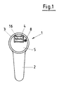
- eine Draufsicht einer Wassermischarmatur mit Anzeigefeld und Reset-Taste,
- Fig. 2
- eine Seitenansicht aus Fig. 1 mit Zuleitung und Bypass mit Durchflußgeber und
- Fig. 3
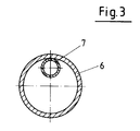
- einen Querschnitt durch eine Zuleitung entsprechend eines zweiten Ausführungsbeispiels mit Strömungskanal und
- Fig. 4
- eine Gesamtansicht einer Armatur
- Fig. 1
- a plan view of a water mixer tap with display panel and reset button,
- Fig. 2
- a side view of Fig. 1 with feed line and bypass with flow sensor and
- Fig. 3
- a cross section through a feed line according to a second embodiment with flow channel and
- Fig. 4
- an overall view of a fitting
Das Kopfteil 3 weist an seiner Oberseite eine Kopffläche oder Abdeckung 5 auf, die mit einer Anzeige 4 zur Anzeige, z. B. der Durchflußmenge des Wassers versehen ist und über eine Reset-Taste 8 nach der Anzeige in die Nullposition verbracht werden kann.
Im hier vorliegenden Ausführungsbeispiel weist die Einhebelmischarmatur 1 zwei Zuleitungen 6, d. h. Wasserzuleitungen 6 auf, die in eine hier nicht näher dargestellte, von einer Kartusche umgebenden Mischkammer führen.The
In the present exemplary embodiment, the single-lever mixer fitting 1 has two
In Fig. 2 ist nur eine der beiden Zuleitungen 6 sichtbar dargestellt, wobei eine der Wasserzuleitungen 6 der Zuführung von Warmwasser und die andere der Zuführung von Kaltwasser dient.In Fig. 2 only one of the two
Im hier vorliegenden Ausführungsbeispiel ist jede der beiden Zuleitungen 6 mit einem Bypass 7, d. h. mit einer Bypassleitung 7 ausgestattet, in die ein Durchflußgeber 10 integriert ist, der wiederum mit der im Kopfteil 3 angeordneten Anzeige 4 verbunden ist, so daß die entsprechenden Durchlaufmengen in der Anzeige 4 erscheinen.In the present exemplary embodiment, each of the two
Bei dem hier vorliegenden Ausführungsbeispiel ist der Bypass 7 nebst dem darin integrierten Durchlaufgeber 10 derart ausgestaltet, daß ein Zehntel der jeweiligen Durchflußmenge der Wasserzuleitung 6 durch den Bypass 7 fließt und so vom Durchlaufgeber 10 derart erfaßt wird, daß diese Durchflußmenge als Signal zur Anzeige 4, z. B. über eine entsprechende elektrische Leitung gelangt, um dann entsprechend multipliziert im Anzeigefeld zu erscheinen.In the present exemplary embodiment, the
Dabei wird berücksichtigt, daß im hier vorliegenden Ausführungsbeispiel jeder Wasserzuleitungen 6 eine entsprechende Bypassleitung 6 mit Durchlaufgeber 10 aufweist, so daß es neben der Multiplikation mit dem Faktor zehn zu einer Addition der Durchflußmengen beider Leitungen 6 kommt und dann die Wasserabgabemenge insgesamt auf der Anzeigefläche erscheint.It is taken into account that in the present exemplary embodiment each
Der Durchlaufgeber 10 kann dabei ein, von durch den Bypass 7 strömendes Wasser umflossenes und angetriebenes Meßrad aufweisen, wobei ebenso eine elektronische Erfassung der Durchlaufmenge denkbar ist, die dann an die mit der Anzeige 4 verbundene Recheneinheit weitergeleitet wird.The
Des weiteren ist in der jeweiligen Bypassleitung 7 eine Einrichtung vorgesehen, die der Justierung der möglichen Durchlaufmenge innerhalb einer bestimmten Zeit dient, um so die Bypassleitung 7 hinsichtlich unterschiedlicher Drücke innerhalb der Wasserleitung 6 jeweils eichen zu können.Furthermore, a device is provided in the
Es wäre jedoch ebenso denkbar, diese unterschiedlichen Drücke innerhalb der Wasserzuleitung 6 durch eine entsprechende Justierung der Meßelektronik einzustellen.However, it would also be conceivable to set these different pressures within the
Im hier vorliegenden Ausführungsbeispiel befindet sich eine, den Querschnitt der Bypassleitung 7 verengende, nicht dargestellte Einstellschraube in der Bypassleitung 7, mit deren Hilfe der Querschnitt entsprechend zu verändern ist.In the present exemplary embodiment there is an adjusting screw, not shown, in the
Wünscht der Bediener der Einhebelmischarmatur 1 eine Anzeige der durchlaufenden Wassermenge, so hat er die Möglichkeit, mittels der Reset-Taste 8, bei bereits erfolgter Benutzung der Armatur 1, zunächst einmal vor Öffnen der Mischarmatur 1 die Durchlaufmengenanzeige 4 im Anzeigenfeld in die Nullstellung zu verbringen, um sodann nach Öffnen der Mischarmatur 1 mittels des Hebels 2 die Durchflußmenge im Anzeigefeld ablesen zu können.If the operator of the single-
Ist nun die gewünschte Abnahmemenge erreicht, so kann der Wasserhahn durch Betätigen des Hebels 2 wieder geschlossen werden.If the required quantity is now reached, the tap can be closed again by operating
Eine weitere Möglichkeit, die Anzeige im Anzeigefeld jeweils vor Benutzung in Nullstellung zu verbringen, besteht darin, daß nach Schließen des Wasserhahns 1 die anzeige 4 selbsttätig die Nullposition unmittelbar einnimmt oder aber auch zeitverzögert.Another way to put the display in the display field before use in each case is that after the
Des weiteren ist vorgesehen, daß in einer weiteren Variante der Erfindung die Möglichkeit besteht, mittels einer entsprechenden Tastatur eine vorbestimmte Wassermenge einzugeben, die dann im Anzeigefeld 4 erscheint, so daß nach Öffnen der Armatur 1 lediglich diese vorbestimmte Wassermenge den Wasserauslauf verläßt und nach Erreichen der entsprechenden, vorbestimmten Wassermenge die Wasserzuleitungen 6 selbsttätig geschlossen werden.Furthermore, it is provided that in a further variant of the invention it is possible to enter a predetermined amount of water using a corresponding keyboard, which then appears in the display field 4, so that after opening the fitting 1 only this predetermined amount of water leaves the water outlet and after reaching the corresponding, predetermined amount of water, the
Eine derartige Dorsiervorrichtung kann dabei mittels einer elektrischen Steuereinrichtung eingestellt werden, so daß nach Erreichen der gewünschten Entnahmemenge ein Magnetventil die Wasserzuleitungen 6 selbsttätig schließt.Such a dorsing device can be adjusted by means of an electrical control device so that a solenoid valve closes the
Die in Fig. 2 dargestellte Bypassleitung 7 kann in hier nicht dargestellter Weise ebenso unmittelbar im Wasserauslaufbereich angeordnet sein, so daß nicht wie im hier vorliegenden Ausführungsbeispiel jeder der Wasserzuleitungen 6 mit einer entsprechenden Bypassleitung 7 mit Durchlaufgeber 10 ausgestattet ist, sondern lediglich eine Bypassleitung 7 mit Durchlaufgeber 10 im Auslaufbereich des Wasserhahnes 1 angeordnet ist.The
Eine derartige Anordnung ändert an der grundsätzlichen Wirkungsweise und dme Aufbau der Vorrichtung nichts.Such an arrangement does not change the basic mode of operation and the structure of the device.
Wie aus Fig. 3 ersichtlich, ist es des weiteren denkbar, die Bypassleitung 7 als Meß- und Strömungskanal mit dem entsprechenden Durchlaufgeber 10 in der Wasserzuleitung 6 unmittelbar anzuordnen, um so eine kompakte Lösung der Aufgabe anzubieten, ohne jedoch auf einen Meßkanal 7 bzw. in seiner Funktion auf eine Bypassleitung verzichten zu müssen.As can be seen from FIG. 3, it is also conceivable to arrange the
Wie aus Fig. 3 ersichtlich, befidet sich hier die Bypassleitung bzw. der Meßkanal 7 unmittelbar in der Wasserzuleitung 6, wobei auch hier durch den Meßkanal 7 etwa 1/10 der durch die Zuleitung 6 strömenden Wassermenge strömt, so daß sichergestellt ist, daß eine ausreichende Wassermenge durch den verbleibenden Wasserzuleitungsquerschnitt gelangt.As can be seen from FIG. 3, the bypass line or the measuring
Des weiteren kann im Bereich der Bypassleitung 7 bzw. in der Bypassleitung ein Temperaturfühler angeordnet sein, der mit der Anzeige 4 in der Mischarmatur 1 gekoppelt ist, so daß mittels der Reset-Taste 8 oder einer weiteren Taste wahlweise die Durchflußmenge oder die Temperatur des abgegebenen Wassers angezeigt werden kann.Furthermore, a temperature sensor can be arranged in the area of the
Der Wasserfluß steuert bei der vorliegenden Erfindung direkt den Meß- bzw. den Dosiervorgang, d. h. beim Öfffnen des Wasserhahnes 1 fließt bzw. beim Schließen des Hahnes 1 steht das Wasser und schaltet entsprechend den Meßvorgang an oder aus.In the present invention, the water flow directly controls the measuring or dosing process, i. H. when the
Die Einrichtung ist somit universal einsetzbar, d. h. in die Zuleitung 6 einer jeden Wasserarmatur mit einfachen Mitteln zu instalieren und kann daher auch nachträglich eingebracht werden.The device is thus universally applicable, d. H. to be installed in the
Fig. 1 zeigt die Draufsicht auf die Armatur 1 wie erwähnt. Auf der Anzeige 4 sind Ziffern 16 erkennbar, wobei es sich hier in der Regel um ein übliches Display handelt, wo also nur die Ziffern erkennbar sind, die den jeweiligen Mengenwert wiedergeben. Die Reset-Taste 8 ist hier für eine mechanische Ausbildung wiedergegeben. Denkbar ist es auch, daß die Ziffernfolge 16 automatisch nach einer bestimmten Zeit gelöscht wird oder aber bei einer neuen Wasserentnahme automatisch auf Null zurückgestellt wird.Fig. 1 shows the top view of the fitting 1 as mentioned.
Fig. 2 zeigt die Seitenansicht der Armatur 1 mit dem Hebel 2 und dem Kopfteil 3, wobei mit 9 das Drehteil bezeichnet ist, das gemäß Fig. 4 endseitig die Küchenbrause 13 trägt.FIG. 2 shows the side view of the fitting 1 with the
Bei der Darstellung nach Fig. 4 ist in die Wasserzuleitung 6 ein Bypass 7 mit dem Durchflußgeber 10 integriert. An den Durchflußgeber 10 angeschlossen ist eine Meßleitung 14, die mit dem hier nicht dargestellten, in der Regel in die Armatur 1 integrierten Chip. Über diesen Chip wird der von dem Durchflußgeber 10 ermittelte Mengenmeßwert umgesetzt und dann im Display bzw. der Anzeige 4 wiedergegeben.4, a
Über die Einstellschraube 11, die vor dem Durchflußgeber 10 in den Bypass 7 integriert ist, kann eine Nachkorrektur vorgenommen werden, insbesondere wenn sich im Laufe der Zeit Abweichungen aufgrund von Durchflußänderungen ergeben oder wenn eine Anpassung auf das Meßgerät bzw. den Durchflußgeber erforderlich ist. Über die Einsteilschraube 11 ist eine einfache und preisgünstige Möglichkeit gegeben, im parallelen Meßkanal den notwendigen und den genauen proportionalen Durchflußwert vorzugeben. Vorteilhaft ist es dabei, den Bypass aus einem Kunststoffrohr herzustellen, um eine Verkalkung zu vermeiden.The adjusting
Mit 15 ein Temperaturfühler bezeichnet, über den gleichzeitig auch die Temperatur des den Bypass durchfließenden Wassers ermittelt werden kann. Dabei kann dieser hier ermittelte Wert auch für den Durchflußgeber mit Berücksichtigung finden. Der Temperaturfühler kann mit einem in die Mischwasserleitung 12 integrierten Temperaturfühler kombiniert verwendet werden.Denoted by 15 is a temperature sensor, via which the temperature of the water flowing through the bypass can be determined at the same time. The value determined here can also be taken into account for the flow transmitter. The temperature sensor can be used in combination with a temperature sensor integrated in the
Alle genannten Merkmale, auch die den Zeichnungen allein zu entnehmenden, werden allein und in Kombination als erfindungswesentlich angesehen.All of the features mentioned, including those that can be seen in the drawings alone, are regarded as essential to the invention, alone and in combination.
Claims (32)
dadurch gekennzeichnet,
daß ein wenigstens zeitweise von Wasser durchströmter mit einer die Durchflußmenge erfaßenden Einrichtung versehener Kanal (7) vorgesehen ist und daß wenigstens eine Einrichtung (4) zur Anzeige der Wasserdurchflußmenge vorgesehen ist.Water fitting, in particular water mixing fitting with at least one water supply serving for the supply of water, with at least one water outlet valve, with at least one water guiding device serving for the delivery of water and at least one actuating member,
characterized,
that a channel (7) through which water flows at least at times and with a device that measures the flow rate is provided, and that at least one device (4) is provided for displaying the water flow rate.
dadurch gekennzeichnet,
daß die Kanalquerschnittsgröße proportional zur Querschnittsgröße des Querschnittes der zugeordneten Wasserführungseinrichtung (6) ausgebildet ist.Water fitting according to claim 1,
characterized,
that the channel cross-sectional size is proportional to the cross-sectional size of the cross section of the associated water guiding device (6).
dadurch gekennzeichnet,
daß der Kanal (7) ein Meßkanal ist.Water fitting according to claim 1 or claim 2,
characterized by
that the channel (7) is a measuring channel.
dadurch gekennzeichnet,
daß der Meßkanal (7) als Bypass ausgebildet ist.Water fitting according to one of claims 1 to 3,
characterized,
that the measuring channel (7) is designed as a bypass.
dadurch gekennzeichnet,
daß der Meßkanal (7) der der Zuführung von Wasser dienenden Wasserführungseinrichtung (6) zugeordnet ist.Water fitting according to one of claims 1 to 4,
characterized,
that the measuring channel (7) is assigned to the water supply device (6) for supplying water.
dadurch gekennzeichnet,
daß zwei der Zuführung von Wasser dienende Wasserführungseinrichtungen (6) vorgesehen sind, daß die beiden Wasserführungseinrichtungen (6) eine Warm- und eine Kaltwasserzuleitung sind und daß jede Wasserzuleitung (6) mit einem Meßkanal (7) versehen ist.Water fitting according to one of claims 1 to 5,
characterized,
that two water supply devices serving to supply water (6) it is provided that the two water supply devices (6) are a hot and a cold water supply line and that each water supply line (6) is provided with a measuring channel (7).
dadurch gekennzeichnet,
daß der Meßkanal (7) den der Abgabe von Wasser dienenden Wasserzuführungseinrichtungen zugeordnet ist.Water fitting according to claim 3,
characterized,
that the measuring channel (7) is assigned to the water supply devices used for dispensing water.
dadurch gekennzeichnet,
daß die Wasserführungseinrichtung ein Wasserauslauf ist.Water fitting according to claim 7,
characterized,
that the water supply device is a water outlet.
dadurch gekennzeichnet,
daß zwei der Abgabe von Wasser dienende Wasserführungseinrichtungen vorgesehen sind, daß die beiden Wasserzuführungseinrichtungen ein Warm- und ein Kaltwasserauslauf sind und daß jeder Auslauf mit einem Meßkanal (7) versehen ist.Water fitting according to one of claims 1 to 4 and / or claim 7 to claim 8,
characterized by
that two water supply devices serving to dispense water are provided, that the two water supply devices are a hot and a cold water outlet and that each outlet is provided with a measuring channel (7).
dadurch gekennzeichnet,
daß der Meßkanal in der Wasserführungseinrichtung angeordnet ist.Water fitting according to one of claims 1 to 3 and / or claim 5 to claim 9,
characterized by
that the measuring channel is arranged in the water guiding device.
dadurch gekennzeichnet,
daß der Meßkanal (7) eine definierte Teilmenge der durch die Wasserführungseinrichtung (6) strömende Wassermenge durchführend ausgestaltet ist.Water fitting according to one of claims 1 to 10,
characterized,
that the measuring channel (7) is designed to carry out a defined subset of the amount of water flowing through the water guiding device (6).
dadurch gekennzeichnet,
daß der Meßkanal (7) 1/10 der durch die zugeordnete Wasserführungseinrichtung (6) strömende Wassermenge durchführend ausgestaltet ist.Water fitting according to one of claims 1 to 11,
characterized by
that the measuring channel (7) is designed to carry out 1/10 of the amount of water flowing through the associated water guiding device (6).
dadurch gekennzeichnet,
daß der Meßkanal (7) eine Querschnittsgröße von 1/10 der Querschnittsgröße der zugeordneten Führungseinrichtung (6) aufweisend ausgestaltet ist.Water fitting according to claim 12,
characterized by
that the measuring channel (7) has a cross-sectional size of 1/10 the cross-sectional size of the associated guide device (6).
dadurch gekennzeichnet,
daß eine Einrichtung zur wahlweisen Verringerung des Strömungsquerschnittes des Meßkanals (6) vorgesehen ist.Water fitting according to one of claims 1 to 13,
characterized by
that a device for selectively reducing the flow cross section of the measuring channel (6) is provided.
dadurch gekennzeichnet,
daß die Einrichtung eine den Querschnitt des Meßkanals (7) verringernde Einstellschraube ist.Water fitting according to claim 14,
characterized by
that the device is an adjusting screw which reduces the cross section of the measuring channel (7).
dadurch gekennzeichnet,
daß die Einrichtung zur Erfassung der Durchflußmenge ein im Meßkanal (7) angeordnetes Meßrad ist.Water fitting according to one of claims 1 to 15,
characterized by
that the device for detecting the flow rate is a measuring wheel arranged in the measuring channel (7).
dadurch gekennzeichnet,
daß die Einrichtung zur Erfassung der Durchflußmenge ein mit dem Meßkanal (7) gekoppeltes und mit wenigstens einem Meßrad versehener Durchlaufgeber (10) ist.Water fitting according to one of claims 1 to 15,
characterized,
that the device for detecting the flow rate is a flow sensor (10) coupled to the measuring channel (7) and provided with at least one measuring wheel.
dadurch gekennzeichnet,
daß ein mit der Einrichtung (4) zur Anzeige der Durchflußmenge in Wirkungseingriff stehender und die durch die Einrichtung (7, 10) zur Erfassung der Durchflußmenge gelieferten Parameter umsetzender und die Anzeigewerte liefernde Elektronik vorgesehen ist.Water fitting according to one of claims 1 to 17,
characterized by
that one which interferes with the device (4) for displaying the flow rate and which is supplied by the device (7, 10) for detecting the flow rate Electronics implementing parameters and providing the display values is provided.
dadurch gekennzeichnet,
daß die Elektronik die verschiedenen Wasserdrücke berücksichtigend ausgestaltet ist.Water fitting according to claim 18,
characterized by
that the electronics are designed taking into account the various water pressures.
dadurch gekennzeichnet,
daß die Anzeige (4) nach Schließen der Armatur (1) selbsttätig in die Nullstellung gehend ausgestaltet ist.Water fitting according to one of claims 1 to 19,
characterized by
that the display (4) is designed to automatically go to the zero position after closing the valve (1).
dadurch gekennzeichnet,
daß die Anzeige (4) nach Schließen der Armatur (1) selbsttätig zeitverzögernd in die Nullstellung gehend ausgestaltet ist.Water fitting according to one of claims 1 to 20,
characterized by
that the display (4) after closing the valve (1) is automatically designed to go into the zero position with a time delay.
dadurch gekennzeichnet,
daß die Anzeige (4) über eine manuell zu betätigende Taste (8) in Nullstellung bringbar ausgestaltet ist.Water fitting according to one of claims 1 to 19,
characterized by
that the display (4) is designed such that it can be brought into zero position by means of a manually operated key (8).
dadurch gekennzeichnet,
daß eine Temperaturanzeige vorgesehen ist.Water fitting according to one of claims 1 to 22,
characterized by
that a temperature display is provided.
dadurch gekennzeichnet,
daß die Anzeige (4) sowohl die Wasserdurchlaufmenge als auch die Temperatur anzeigbar ausgestaltet ist.Water fitting according to one of claims 1 to 23,
characterized by
that the display (4) is designed to display both the water flow rate and the temperature.
dadurch gekennzeichnet,
daß die Anzeige (4) ein Temperaturanzeige dienendes separates Anzeigefeld aufweist.Water fitting according to one of claims 1 to 24,
characterized by
that the display (4) is a separate temperature display Display field.
dadurch gekennzeichnet,
daß die Anzeige (4) wahlweise die Temperatur oder die Wasserdurchflußmenge anzeigbar ausgestaltet ist.Water fitting according to one of claims 1 to 25,
characterized by
that the display (4) is optionally designed to display the temperature or the water flow rate.
dadurch gekennzeichnet,
daß die Anzeige (4) im Betätigungshebel der Armatur angeordnet ist.Water fitting according to one of claims 1 to 26,
characterized by
that the display (4) is arranged in the operating lever of the valve.
dadurch gekennzeichnet,
daß die Anzeige (4) im Kopf der Armatur angeordnet ist.Water fitting according to one of claims 1 to 26,
characterized by
that the display (4) is arranged in the head of the fitting.
dadurch gekennzeichnet,
daß die Elektronik einem Chip zugeordnet ist.Water fitting according to claim 18,
characterized by
that the electronics are assigned to a chip.
dadurch gekennzeichnet,
daß die Elektronik, vorzugsweise der Chip mit der Einrichtung zur Erfassung der Durchflußmenge in die Armatur (1) integriert ist.Water fitting according to claim 18 and claim 19,
characterized by
that the electronics, preferably the chip, is integrated with the device for detecting the flow rate in the fitting (1).
dadurch gekennzeichnet,
daß die Elektronik, vorzugsweise der Chip mit der Einrichtung zur Erfassung der Durchflußmenge der Armatur (1) vorgeschaltet ist.Water fitting according to claim 18 and claim 19,
characterized by
that the electronics, preferably the chip with the device for detecting the flow rate of the valve (1) is connected upstream.
dadurch gekennzeichnet,
daß die Ermittlung der Durchflußmenge über die sogenannte Mikrosystemtechnik erfolgt, vorzugsweise mit Ermittlung der Parameter Druck und Zeit.Water fitting according to claim 1 to claim 31,
characterized by
that the determination of the flow rate via the so-called Microsystem technology takes place, preferably by determining the parameters of pressure and time.
Applications Claiming Priority (2)
| Application Number | Priority Date | Filing Date | Title |
|---|---|---|---|
| DE9216922U DE9216922U1 (en) | 1992-12-15 | 1992-12-15 | |
| DE9216922U | 1992-12-15 |
Publications (2)
| Publication Number | Publication Date |
|---|---|
| EP0602629A1 true EP0602629A1 (en) | 1994-06-22 |
| EP0602629B1 EP0602629B1 (en) | 1997-03-05 |
Family
ID=6887048
Family Applications (1)
| Application Number | Title | Priority Date | Filing Date |
|---|---|---|---|
| EP93120233A Expired - Lifetime EP0602629B1 (en) | 1992-12-15 | 1993-12-15 | Watertap, in particular water mixer-tap with flow measuring device |
Country Status (6)
| Country | Link |
|---|---|
| EP (1) | EP0602629B1 (en) |
| AT (1) | ATE149676T1 (en) |
| DE (2) | DE9216922U1 (en) |
| DK (1) | DK0602629T3 (en) |
| ES (1) | ES2103054T3 (en) |
| GR (1) | GR3023704T3 (en) |
Cited By (1)
| Publication number | Priority date | Publication date | Assignee | Title |
|---|---|---|---|---|
| EP0979681A1 (en) * | 1998-08-11 | 2000-02-16 | Société SOTEP | Tubular mouth piece for an extremity of an irrigation hose |
Families Citing this family (6)
| Publication number | Priority date | Publication date | Assignee | Title |
|---|---|---|---|---|
| DE29606674U1 (en) * | 1996-04-12 | 1996-08-22 | Wehrle E Gmbh | Combined cold and hot water meter |
| DE19937433A1 (en) * | 1999-08-07 | 2001-02-08 | Marc Bell | Water outlet arrangement, having cold and hot water valve which regulate flow quantity, and preferably open flow to mixer |
| ES2303745B1 (en) * | 2005-09-13 | 2009-07-23 | Jose Jodar Garcia | MONOMANDO TAP WITH LED DIODE. |
| US9068327B2 (en) * | 2012-05-19 | 2015-06-30 | Oskar L. Granstrand | Flow meter for the measuring of fluid volumes originating from a faucet |
| DE102015109957B4 (en) * | 2015-06-22 | 2017-06-08 | Lorenz Gmbh & Co. Kg | Flow water meters |
| CN112539781B (en) * | 2020-12-01 | 2022-06-07 | 抚州市银圣王洁具有限公司 | Water tap pressure and flow detection device |
Citations (8)
| Publication number | Priority date | Publication date | Assignee | Title |
|---|---|---|---|---|
| FR708266A (en) * | 1930-12-23 | 1931-07-22 | Tapping tap with totalizer | |
| DE563246C (en) * | 1931-07-04 | 1932-11-03 | Edmund Bittner | Measuring tap, especially for beer |
| US1946275A (en) * | 1928-09-17 | 1934-02-06 | American Cyanamid Co | Fluid measuring apparatus |
| CH558933A (en) * | 1974-03-23 | 1975-02-14 | Bryant Robert | Water meter for domestic tap - has digital indicator with resetting button |
| US3937362A (en) * | 1972-09-15 | 1976-02-10 | Aktiebolaget Demektor | Liquid dosage device having rotary feeler |
| GB2028436A (en) * | 1978-08-24 | 1980-03-05 | Agmet Instr | Fluid-flow Metering Devices |
| DE3546504A1 (en) * | 1985-07-13 | 1987-03-19 | Ideal Standard | Sanitary mixer tap |
| US4756030A (en) * | 1987-09-23 | 1988-07-12 | Juliver Steven J | Bathroom controller |
-
1992
- 1992-12-15 DE DE9216922U patent/DE9216922U1/de not_active Expired - Lifetime
-
1993
- 1993-12-15 EP EP93120233A patent/EP0602629B1/en not_active Expired - Lifetime
- 1993-12-15 DE DE59305616T patent/DE59305616D1/en not_active Expired - Fee Related
- 1993-12-15 DK DK93120233.7T patent/DK0602629T3/en active
- 1993-12-15 AT AT93120233T patent/ATE149676T1/en not_active IP Right Cessation
- 1993-12-15 ES ES93120233T patent/ES2103054T3/en not_active Expired - Lifetime
-
1997
- 1997-06-05 GR GR970401345T patent/GR3023704T3/en unknown
Patent Citations (8)
| Publication number | Priority date | Publication date | Assignee | Title |
|---|---|---|---|---|
| US1946275A (en) * | 1928-09-17 | 1934-02-06 | American Cyanamid Co | Fluid measuring apparatus |
| FR708266A (en) * | 1930-12-23 | 1931-07-22 | Tapping tap with totalizer | |
| DE563246C (en) * | 1931-07-04 | 1932-11-03 | Edmund Bittner | Measuring tap, especially for beer |
| US3937362A (en) * | 1972-09-15 | 1976-02-10 | Aktiebolaget Demektor | Liquid dosage device having rotary feeler |
| CH558933A (en) * | 1974-03-23 | 1975-02-14 | Bryant Robert | Water meter for domestic tap - has digital indicator with resetting button |
| GB2028436A (en) * | 1978-08-24 | 1980-03-05 | Agmet Instr | Fluid-flow Metering Devices |
| DE3546504A1 (en) * | 1985-07-13 | 1987-03-19 | Ideal Standard | Sanitary mixer tap |
| US4756030A (en) * | 1987-09-23 | 1988-07-12 | Juliver Steven J | Bathroom controller |
Cited By (2)
| Publication number | Priority date | Publication date | Assignee | Title |
|---|---|---|---|---|
| EP0979681A1 (en) * | 1998-08-11 | 2000-02-16 | Société SOTEP | Tubular mouth piece for an extremity of an irrigation hose |
| FR2782366A1 (en) * | 1998-08-11 | 2000-02-18 | Sotep | TUBULAR PART FOR FITTING THE END OF A WATERING HOSE |
Also Published As
| Publication number | Publication date |
|---|---|
| DE9216922U1 (en) | 1993-06-17 |
| DK0602629T3 (en) | 1997-09-08 |
| DE59305616D1 (en) | 1997-04-10 |
| ATE149676T1 (en) | 1997-03-15 |
| GR3023704T3 (en) | 1997-09-30 |
| ES2103054T3 (en) | 1997-08-16 |
| EP0602629B1 (en) | 1997-03-05 |
Similar Documents
| Publication | Publication Date | Title |
|---|---|---|
| DE10126598B4 (en) | Apparatus and method for providing a mixed beverage | |
| DE60127482T2 (en) | Water purification system with measurement and control of delivery | |
| DE3030716A1 (en) | VALVE DEVICE | |
| EP2069227A1 (en) | Method of filling containers with a liquid filling substance | |
| DE4342096A1 (en) | Device for metering fluids and beverage dispensing system with such a metering device | |
| DE2730375A1 (en) | Fluid measuring and metering system - is used in paint sprayer and performs dynamic flow measuring to control mixing valve | |
| EP2070458A1 (en) | Method for detecting a flow in a coffee machine and coffee machine to implement the method | |
| DE102010008166A1 (en) | Method and filling system for volume and / or quantity-controlled filling of containers with a filling material consisting of at least two components | |
| EP0602629B1 (en) | Watertap, in particular water mixer-tap with flow measuring device | |
| DE3400263C2 (en) | ||
| AT501226A2 (en) | COMPENSATOR TAP, METHOD OF TAPPING BEVERAGES AND USE OF A COMPENSATOR TAP | |
| DE3209166A1 (en) | METHOD AND DEVICE FOR FILLING CONTAINERS CLOSED WITH FILL AND TAP Faucets, preferably KEGS | |
| EP0236693A1 (en) | Device for observing and controlling a flowable product transported through a tube | |
| EP0914291B1 (en) | Device for the measured transferring of several homogeneous liquids of the same kind | |
| WO1992001980A1 (en) | Compact filling device for adjustable quantities of water for domestic use | |
| EP0087455B1 (en) | Test device | |
| DE3710968A1 (en) | DEVICE FOR MEASURING THE VOLUME OR MASS CURRENT | |
| DE4329784A1 (en) | Drinks tapping system having a drinks metering device and a cleaning device | |
| DE19831993C1 (en) | Valve for liquid medium e.g. for heating or cooling or air conditioning systems with a flow quantity setting arrangement | |
| EP1211487B1 (en) | Device for measuring and controlling consumption of heat transferring fluids | |
| DE2912583A1 (en) | Sanitary fitting mixing valve - has single auxiliary valve with solenoid for separate inlet stop valves | |
| DE3214734A1 (en) | Device for measuring the milk quantity and/or monitoring the milk flow and process for measuring the quantity of milk yielded by a cow during a milking operation and/or for monitoring the milk flow during the milking operation using the device | |
| DE102005037334B3 (en) | Measuring system for determining flow rate of fluid media, has control and evaluation unit, controlling measuring channels and signal electronics, accommodated with area of one channel and signal electronics in common housing | |
| DE19718454A1 (en) | Differential pressure gauge able to transmit pressure and valve state at distance for e.g. management, hospitals | |
| EP1245904B1 (en) | Device for flushing and/or filling a fluid circuit of a solar installation |
Legal Events
| Date | Code | Title | Description |
|---|---|---|---|
| PUAI | Public reference made under article 153(3) epc to a published international application that has entered the european phase |
Free format text: ORIGINAL CODE: 0009012 |
|
| AK | Designated contracting states |
Kind code of ref document: A1 Designated state(s): AT BE CH DE DK ES FR GB GR IE IT LI LU MC NL PT SE |
|
| 17P | Request for examination filed |
Effective date: 19940728 |
|
| 17Q | First examination report despatched |
Effective date: 19950915 |
|
| GRAG | Despatch of communication of intention to grant |
Free format text: ORIGINAL CODE: EPIDOS AGRA |
|
| GRAH | Despatch of communication of intention to grant a patent |
Free format text: ORIGINAL CODE: EPIDOS IGRA |
|
| GRAH | Despatch of communication of intention to grant a patent |
Free format text: ORIGINAL CODE: EPIDOS IGRA |
|
| GRAA | (expected) grant |
Free format text: ORIGINAL CODE: 0009210 |
|
| AK | Designated contracting states |
Kind code of ref document: B1 Designated state(s): AT BE CH DE DK ES FR GB GR IE IT LI LU MC NL PT SE |
|
| REF | Corresponds to: |
Ref document number: 149676 Country of ref document: AT Date of ref document: 19970315 Kind code of ref document: T |
|
| REG | Reference to a national code |
Ref country code: CH Ref legal event code: EP |
|
| REF | Corresponds to: |
Ref document number: 59305616 Country of ref document: DE Date of ref document: 19970410 |
|
| REG | Reference to a national code |
Ref country code: IE Ref legal event code: FG4D Free format text: 72350 |
|
| ITF | It: translation for a ep patent filed |
Owner name: ING. C. GREGORJ S.P.A. |
|
| ET | Fr: translation filed | ||
| REG | Reference to a national code |
Ref country code: CH Ref legal event code: NV Representative=s name: PATENTANWAELTE GEORG ROEMPLER UND ALDO ROEMPLER |
|
| GBT | Gb: translation of ep patent filed (gb section 77(6)(a)/1977) |
Effective date: 19970630 |
|
| REG | Reference to a national code |
Ref country code: ES Ref legal event code: FG2A Ref document number: 2103054 Country of ref document: ES Kind code of ref document: T3 |
|
| REG | Reference to a national code |
Ref country code: GR Ref legal event code: FG4A Free format text: 3023704 |
|
| REG | Reference to a national code |
Ref country code: DK Ref legal event code: T3 |
|
| PGFP | Annual fee paid to national office [announced via postgrant information from national office to epo] |
Ref country code: GR Payment date: 19971119 Year of fee payment: 5 |
|
| PGFP | Annual fee paid to national office [announced via postgrant information from national office to epo] |
Ref country code: SE Payment date: 19971124 Year of fee payment: 5 Ref country code: MC Payment date: 19971124 Year of fee payment: 5 |
|
| PGFP | Annual fee paid to national office [announced via postgrant information from national office to epo] |
Ref country code: PT Payment date: 19971126 Year of fee payment: 5 Ref country code: FR Payment date: 19971126 Year of fee payment: 5 |
|
| PGFP | Annual fee paid to national office [announced via postgrant information from national office to epo] |
Ref country code: AT Payment date: 19971127 Year of fee payment: 5 |
|
| PGFP | Annual fee paid to national office [announced via postgrant information from national office to epo] |
Ref country code: IE Payment date: 19971204 Year of fee payment: 5 |
|
| PGFP | Annual fee paid to national office [announced via postgrant information from national office to epo] |
Ref country code: GB Payment date: 19971209 Year of fee payment: 5 |
|
| PGFP | Annual fee paid to national office [announced via postgrant information from national office to epo] |
Ref country code: BE Payment date: 19971212 Year of fee payment: 5 |
|
| PGFP | Annual fee paid to national office [announced via postgrant information from national office to epo] |
Ref country code: DK Payment date: 19971222 Year of fee payment: 5 |
|
| PGFP | Annual fee paid to national office [announced via postgrant information from national office to epo] |
Ref country code: ES Payment date: 19971226 Year of fee payment: 5 |
|
| PGFP | Annual fee paid to national office [announced via postgrant information from national office to epo] |
Ref country code: NL Payment date: 19971231 Year of fee payment: 5 |
|
| PGFP | Annual fee paid to national office [announced via postgrant information from national office to epo] |
Ref country code: LU Payment date: 19980106 Year of fee payment: 5 |
|
| PLBE | No opposition filed within time limit |
Free format text: ORIGINAL CODE: 0009261 |
|
| STAA | Information on the status of an ep patent application or granted ep patent |
Free format text: STATUS: NO OPPOSITION FILED WITHIN TIME LIMIT |
|
| 26N | No opposition filed | ||
| PG25 | Lapsed in a contracting state [announced via postgrant information from national office to epo] |
Ref country code: LU Free format text: LAPSE BECAUSE OF NON-PAYMENT OF DUE FEES Effective date: 19981215 Ref country code: IE Free format text: LAPSE BECAUSE OF NON-PAYMENT OF DUE FEES Effective date: 19981215 Ref country code: GB Free format text: LAPSE BECAUSE OF NON-PAYMENT OF DUE FEES Effective date: 19981215 Ref country code: DK Free format text: LAPSE BECAUSE OF NON-PAYMENT OF DUE FEES Effective date: 19981215 Ref country code: AT Free format text: LAPSE BECAUSE OF NON-PAYMENT OF DUE FEES Effective date: 19981215 |
|
| PG25 | Lapsed in a contracting state [announced via postgrant information from national office to epo] |
Ref country code: SE Free format text: LAPSE BECAUSE OF NON-PAYMENT OF DUE FEES Effective date: 19981216 |
|
| PG25 | Lapsed in a contracting state [announced via postgrant information from national office to epo] |
Ref country code: GR Free format text: LAPSE BECAUSE OF NON-PAYMENT OF DUE FEES Effective date: 19981231 Ref country code: BE Free format text: LAPSE BECAUSE OF NON-PAYMENT OF DUE FEES Effective date: 19981231 |
|
| BERE | Be: lapsed |
Owner name: KLUDI-ARMATUREN PAUL SCHEFFER K.G. Effective date: 19981231 |
|
| PG25 | Lapsed in a contracting state [announced via postgrant information from national office to epo] |
Ref country code: PT Free format text: LAPSE BECAUSE OF NON-PAYMENT OF DUE FEES Effective date: 19990630 Ref country code: MC Free format text: LAPSE BECAUSE OF NON-PAYMENT OF DUE FEES Effective date: 19990630 |
|
| PG25 | Lapsed in a contracting state [announced via postgrant information from national office to epo] |
Ref country code: NL Free format text: LAPSE BECAUSE OF NON-PAYMENT OF DUE FEES Effective date: 19990701 |
|
| GBPC | Gb: european patent ceased through non-payment of renewal fee |
Effective date: 19981215 |
|
| PG25 | Lapsed in a contracting state [announced via postgrant information from national office to epo] |
Ref country code: FR Free format text: LAPSE BECAUSE OF NON-PAYMENT OF DUE FEES Effective date: 19990831 |
|
| NLV4 | Nl: lapsed or anulled due to non-payment of the annual fee |
Effective date: 19990701 |
|
| REG | Reference to a national code |
Ref country code: FR Ref legal event code: ST |
|
| REG | Reference to a national code |
Ref country code: PT Ref legal event code: MM4A Free format text: LAPSE DUE TO NON-PAYMENT OF FEES Effective date: 19990630 |
|
| PG25 | Lapsed in a contracting state [announced via postgrant information from national office to epo] |
Ref country code: ES Free format text: LAPSE BECAUSE OF NON-PAYMENT OF DUE FEES Effective date: 19991216 |
|
| REG | Reference to a national code |
Ref country code: DK Ref legal event code: EBP |
|
| PGFP | Annual fee paid to national office [announced via postgrant information from national office to epo] |
Ref country code: CH Payment date: 20001207 Year of fee payment: 8 |
|
| PGFP | Annual fee paid to national office [announced via postgrant information from national office to epo] |
Ref country code: DE Payment date: 20010117 Year of fee payment: 8 |
|
| PG25 | Lapsed in a contracting state [announced via postgrant information from national office to epo] |
Ref country code: LI Free format text: LAPSE BECAUSE OF NON-PAYMENT OF DUE FEES Effective date: 20011231 Ref country code: CH Free format text: LAPSE BECAUSE OF NON-PAYMENT OF DUE FEES Effective date: 20011231 |
|
| PG25 | Lapsed in a contracting state [announced via postgrant information from national office to epo] |
Ref country code: DE Free format text: LAPSE BECAUSE OF NON-PAYMENT OF DUE FEES Effective date: 20020702 |
|
| REG | Reference to a national code |
Ref country code: CH Ref legal event code: PL |
|
| REG | Reference to a national code |
Ref country code: ES Ref legal event code: FD2A Effective date: 20000114 |
|
| PG25 | Lapsed in a contracting state [announced via postgrant information from national office to epo] |
Ref country code: IT Free format text: LAPSE BECAUSE OF NON-PAYMENT OF DUE FEES;WARNING: LAPSES OF ITALIAN PATENTS WITH EFFECTIVE DATE BEFORE 2007 MAY HAVE OCCURRED AT ANY TIME BEFORE 2007. THE CORRECT EFFECTIVE DATE MAY BE DIFFERENT FROM THE ONE RECORDED. Effective date: 20051215 |