EP0945862A2 - Recherche d'images - Google Patents
Recherche d'images Download PDFInfo
- Publication number
- EP0945862A2 EP0945862A2 EP99302235A EP99302235A EP0945862A2 EP 0945862 A2 EP0945862 A2 EP 0945862A2 EP 99302235 A EP99302235 A EP 99302235A EP 99302235 A EP99302235 A EP 99302235A EP 0945862 A2 EP0945862 A2 EP 0945862A2
- Authority
- EP
- European Patent Office
- Prior art keywords
- image
- frame
- frame image
- index
- time position
- Prior art date
- Legal status (The legal status is an assumption and is not a legal conclusion. Google has not performed a legal analysis and makes no representation as to the accuracy of the status listed.)
- Withdrawn
Links
- 238000000034 method Methods 0.000 claims abstract description 40
- 239000000463 material Substances 0.000 description 18
- 230000000694 effects Effects 0.000 description 10
- 238000010586 diagram Methods 0.000 description 7
- 238000001514 detection method Methods 0.000 description 5
- 238000010276 construction Methods 0.000 description 4
- 102100022465 Methanethiol oxidase Human genes 0.000 description 1
- 102100031798 Protein eva-1 homolog A Human genes 0.000 description 1
- 230000006835 compression Effects 0.000 description 1
- 238000007906 compression Methods 0.000 description 1
- 239000000284 extract Substances 0.000 description 1
- 238000012986 modification Methods 0.000 description 1
- 230000004048 modification Effects 0.000 description 1
- 230000001105 regulatory effect Effects 0.000 description 1
- 238000005070 sampling Methods 0.000 description 1
- 230000001360 synchronised effect Effects 0.000 description 1
Images


Classifications
-
- G—PHYSICS
- G11—INFORMATION STORAGE
- G11B—INFORMATION STORAGE BASED ON RELATIVE MOVEMENT BETWEEN RECORD CARRIER AND TRANSDUCER
- G11B27/00—Editing; Indexing; Addressing; Timing or synchronising; Monitoring; Measuring tape travel
- G11B27/02—Editing, e.g. varying the order of information signals recorded on, or reproduced from, record carriers
- G11B27/031—Electronic editing of digitised analogue information signals, e.g. audio or video signals
- G11B27/034—Electronic editing of digitised analogue information signals, e.g. audio or video signals on discs
-
- G—PHYSICS
- G11—INFORMATION STORAGE
- G11B—INFORMATION STORAGE BASED ON RELATIVE MOVEMENT BETWEEN RECORD CARRIER AND TRANSDUCER
- G11B27/00—Editing; Indexing; Addressing; Timing or synchronising; Monitoring; Measuring tape travel
- G11B27/10—Indexing; Addressing; Timing or synchronising; Measuring tape travel
- G11B27/102—Programmed access in sequence to addressed parts of tracks of operating record carriers
- G11B27/105—Programmed access in sequence to addressed parts of tracks of operating record carriers of operating discs
-
- G—PHYSICS
- G11—INFORMATION STORAGE
- G11B—INFORMATION STORAGE BASED ON RELATIVE MOVEMENT BETWEEN RECORD CARRIER AND TRANSDUCER
- G11B27/00—Editing; Indexing; Addressing; Timing or synchronising; Monitoring; Measuring tape travel
- G11B27/10—Indexing; Addressing; Timing or synchronising; Measuring tape travel
- G11B27/19—Indexing; Addressing; Timing or synchronising; Measuring tape travel by using information detectable on the record carrier
- G11B27/28—Indexing; Addressing; Timing or synchronising; Measuring tape travel by using information detectable on the record carrier by using information signals recorded by the same method as the main recording
-
- G—PHYSICS
- G11—INFORMATION STORAGE
- G11B—INFORMATION STORAGE BASED ON RELATIVE MOVEMENT BETWEEN RECORD CARRIER AND TRANSDUCER
- G11B27/00—Editing; Indexing; Addressing; Timing or synchronising; Monitoring; Measuring tape travel
- G11B27/10—Indexing; Addressing; Timing or synchronising; Measuring tape travel
- G11B27/34—Indicating arrangements
Definitions
- the present invention relates to an image searching device and a image searching method.
- Embodiments of the invention apply the device and method to an editing list forming device for specifying a desired part in the image and sound based on the video audio data as a clip for example.
- this type of editing list forming device when reproducing images and sounds based on the video audio data at high speed, the operator specifies a desired part in images and sounds based on the video audio data as a clip by visually confirming images displayed on the display as well as listening to sounds output from the speaker corresponding to the images.
- Embodiments of the present invention seek to provide an image searching device and image searching method, in which operational efficiencies of editing works can be remarkably improved.
- An embodiment of the present invention provides an image searching device and the image searching method for searching the desired frame image from a sequence of multiple frame images.
- Frame images are sequentially extracted from multiple frame images at established extracting intervals with using the extracting means. After each frame image extracted is scaled down, each of the resulting index image is displayed on the display means by the display control means and simultaneously the extracting intervals will be set by the interval setting means according to the external operation.
- the desired index image can be selected from multiple index images displayed on the display means, the desired index image can be selected more easily and in a shorter period of time than in case of conventional searching multiple frame images successively from the beginning.
- the amplitude of audio data corresponding to the selected frame images according to the internal operation can be displayed on the display means by the audio display means.
- the processing can be conducted in a shorter period of time than the case where the operator conducts this type of work by actually listening to the sounds.
- FIG. 1, 1 generally shows an editing list forming device as an illustrative image searching device according to the present invention.
- Video audio data D AV supplied from the outside is supplied to a video capture board 5 provided in a control unit 4 via an input unit 2 and Ethernet 3, and simultaneously, to a server editing device 6.
- This video capture board 5 after converting the video audio data D AV to digital data, sequentially captures frame images of the motion video data D JP formed per frame into the hard disc device 7 by compression coding with the motion joint photographic coding expert group (JPEG) system and also captures the audio data D A which is applied to the sampling per frame in synchronous with the motion video data D JP into the hard disc device 7.
- JPEG motion joint photographic coding expert group
- the hard disc device 7 stores the motion video data D JP captured into the file, with specifying the address per frame, as well as storing audio data D A into the file with specifying the address per unit corresponding to one frame.
- the application is set for the control unit 4 to randomly access sequentially to the motion video data D JP and audio data D A with making the time required for reading and writing one frame image as an access unit.
- the motion video data D JP and audio data D A based on multiple video audio data D AV are stored and the motion video data D JP and audio data D A based on the desired video audio data D AV are selectively read out upon request according to the predetermined procedure.
- the control unit 4 displays the predetermined operation screen (hereinafter referred to as main screen) on the display 8 at the initial stage.
- main screen the predetermined operation screen
- the control unit 4 transmits these data to the video capture board 5.
- the video capture board 5 restores multiple frame images to the original frame images by conducting the expansion coding processing based on the motion video data D JP, and converts the sound corresponding to the frame image to analog mode when necessary.
- an operator can specify the desired part of video and audio by operating a mouse 9 based on the images displayed on the display 8 and the sound from a speaker 10. Moreover, making the specified part as the clip, related data such as the time code and duration of its in-point and out-point can be registered in the control unit 4.
- This server editing device 6 extracts video and audio corresponding to the clip specified on the video audio data D AV supplied via the input unit 2 and the Ethernet 3, and edits each clip to various states such as special effects according to the operator's command.
- the control unit 4 firstly displays graphical user interface (GUI) screen 20 as shown in Fig. 3 on the display screen of the display 8 based on the program stored in the internal ROM (not shown in Fig.).
- GUI graphical user interface
- this GUI screen 20 there are provided multiple buttons 21A ⁇ 21C for selecting the processing contents the operator desires, a data display unit 22 for displaying the contents corresponding to the selected buttons 21A ⁇ 21C, multiple buttons 23A ⁇ 23Z for specifying various processing when making the clip, and an editing list forming unit 24 for making the clip.
- this GUI screen 20 Under the condition in which this GUI screen 20 is displayed on the display 8, when an editing button "Editing" 21A on the upper part of the screen is selected by the operation of the mouse 9, the control unit 4 displays a window 30 as shown in Fig. 4 (hereinafter referred to as clip forming window) on the left side of the data display unit 22 of the GUI screen 20 in layers, and a selected material display window 31 on the right side of the data display unit 22 in layers.
- the clip forming window 30 is a window for specifying the desired part of the video audio materials as the clip.
- said representative images 28A and 28B of the image audio material can be displayed in the live video display unit 34.
- multiple detection selection buttons 32A ⁇ 32C corresponding to the types of detecting the clip are displayed on the upper left side. By selecting one of these detection selection buttons 32A ⁇ 32C by operation of the mouse 9, the desired clip detection method can be selected.
- the control unit 4 displays the motion video data D JP sequentially read out from the hard disc 7 in the live video display part 34 in the clip forming window 30 with the contents corresponding to the selected video operation button 33A. Also, when the slider 35 in the clip forming window 30 is operated, it displays the contents specified in the live video display part 34 in the same manner.
- the operator can specify the in-point and out-point of the video part at which he desires to register as the clip.
- images of the in-point and out-point specified are respectively displayed in the in-point image display unit 38 or out-point image display unit 39.
- the length from the in-point to out-point is displayed on the duration display unit 41.
- the control unit 4 captures the related data such as time code of the in-point and out-point of the clip displayed on the display 8, the length of material and the storage position (in the hard disc) in the internal RAM (not shown in Fig.) as database, while displaying the frame image of the in-point and out-point of the registered clip in the selected material display window 31 in addition to the representative images 28A and 28B of the original video audio materials.
- the control unit 4 displays a window 45 as shown in Fig. 5 (hereinafter referred to as index window) in place of the selected material display window 31 at the right side of the information display unit 22.
- index window 45 15 frame images, each of which is scaled down to the predetermined size are displayed as index images IN1 ⁇ IN15.
- 3 tab buttons, "MIN”, “SEC” and “FRAME” (hereinafter referred to as MIN tab button, SEC tab button and FRM tab button) 46A ⁇ 46C are displayed according to the index display method when detecting the clip.
- the control unit 4 sequentially reads out frame images per minute, i.e., per 1800 frames based on the frame image displayed on the live video display part 34 in the clip forming window 30, when reading out the motion video data D JP from the hard disc 7. Then, the control unit 4 scales them down to the index image respectively, and displays them on the index window 45.
- the control unit 4 sequentially reads out frame images per second, i.e., per 30 frames, based on the frame image according to the selected index image from presently displayed 15 index images extracted per minute, when reading out the motion video data D JP from the hard disc 7. Then, the control unit 4 scales them down to the index images respectively, and displays on the index window 45.
- the control unit 4 continuously reads out frame images based on the frame image corresponding to the selected index image from presently displayed 15 index images extracted per minute when reading out the motion video data D JP from the hard disc 7. Then, the control unit 4 scales them down to the index images respectively, and displays them on the index window 45.
- the control unit 4 displays the time position of the selected index image as the slider 48 on the center of the audio display unit 47 provided in the index window 45, and displays the sound for approximately 2 seconds around the slider 48 as the waveform AE (hereinafter referred to as audio amplitude envelope), presuming the time as the abscissas and the amplitude as the ordinates.
- the control unit 4 specifies the index image corresponding to the time position shown by the slider 48 within the screen.
- sound reproduction button for reproducing the sound for approximately 2 seconds around the time position of the selected index image (these reproduction buttons are referred to as previous sound reproduction button and next sound reproduction button) 49 and 50 are provided and the sound corresponding to said previous sound reproduction button 49 or the next sound reproduction button 50 is put out from the speaker 10 for approximately 2 seconds by operating the mouse 9.
- a PREV button 51 and a NEXT button 52 for displaying the same number of index images as presently-displayed 15 index images, moving backward or forward on the time axis are provided.
- the PREV button or NEXT button is selected by operating the mouse 9, 15 index images are displayed in scrolling forward or backward in time.
- the slider 53 is provided between the PREV button 51 and the NEXT button 52 and the index images can be specified by operating said slider 53.
- the editing list can be formed according to the method to be described below, using the time line window 60.
- the operator after moving the cursor (not shown in Fig.) onto the frame image of the in-point of the desired clip in the selected material display window 31, the operator should press the button of the mouse 9. Under this condition, the operator is to move the cursor to the desired position on the video track 24E among multiple tracks 24A ⁇ 24I forming the editing list forming unit 24 provided along the time scale 61, with regarding the time scale 61 as an index in the time line window 60, and release the button of the mouse 9.
- a bar 62A having the predetermined color and the length corresponding to the material length of the specified clip is shown.
- the bar 62B having the same length as the bar 62A displayed on the video track 24E is also displayed on the audio track 24F at the same position according to the time scale 61.
- the operator repeats the operation described above, to sequentially display the bar 62A and 62B on the video track 24E and audio track 24F continuouly from the start time code ("00.00.00:00") to the desired time code (i.e., for the length of target time) on the time scale 61.
- the bar 62A and 62B are displayed on the video track 24E and the audio track 24F on the time line window 60. This means that the clip images corresponding to the bar 62A are displayed or the sound corresponding to the bar 62B is output at the time shown by the time scale 61 when the edited video and sound are output. Accordingly, with such an operation, the editing list sequentially regulating the clip video displayed as edited video or the clip sound output as the edited sound can be formed.
- the operator should click the special effect selection button 23P from multiple buttons 23A ⁇ 23T provided on the upper part of the time line window 60 for selecting various processing.
- the predetermined window (not shown in Fig.), on which multiple icons showing the contents of various special effect processing (hereinafter referred to as effect icons) are displayed, can be opened.
- effect icons multiple icons showing the contents of various special effect processing
- the icon corresponding to the desired special effect processing in the window can be displayed on the predetermined position of the effect track 24D of the time line window 60.
- the operator can input a command to execute the special effect processing corresponding to the effect icon pasted as described above.
- this editing list forming device 1 the operator selects the desired video audio material from multiple video audio materials stored in the hard disc device and can form the clip specifying the in-point and out-point, so as to form the editing list based on the specified clip.
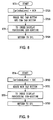
- the control unit 4 executes the clip specification processing procedure RT1 shown in Fig. 6 in order to determine the in-point and out-point of the clip which the operator desired.
- the control unit 4 enters into the clip specification processing procedure RT1 that is the main routine from the step SP0, and initializes the index window 45 by executing the following sub-routine RT2. In this case, the control unit 4 initializes all variable numbers that can be set in the index window 45. At the same time, the control unit 4 displays the audio amplitude envelope AE showing the sound for approximately for 2 seconds around the time position of the index image in the audio display unit 47, regarding the currently-displayed index image at the head position as the selected index image.
- control unit 4 waits till the operator operates the mouse 9 at the step SP1.
- the control unit 4 judges whether MIN tab button 46A is selected or not. If an affirmative result is obtained, the control unit 4 proceeds to the sub-routine RT3, and displays the index image extracted per minute corresponding to the MIN tab button 46A in the index window 45.
- the control unit 4 proceeds to the step SP3, and judges whether the SEC tab button 46B is selected or not.
- the control unit 4 proceeds to the sub-routine RT4, and displays the index image extracted per second in response to the SEC tab button 46C in the index window 45.
- the case where negative result is obtained means that FRM tab button 46C is selected. In this case, the control unit 4 proceeds to the step SP4 and judges whether an index image out of 15 index images is single-clicked by operating the mouse 9 or not.
- the case when an affirmative result is obtained means that said index image is selected.
- the control unit 4 proceeds to the sub-routine RT5 and displays the audio amplitude envelope AE showing the sound for approximately 2 seconds around the time position of the selected index image.
- the control unit 4 proceeds to the step SP5, and judges whether one index image out of 15 index images is double clicked by operating the mouse 9 or not.
- control unit 4 proceeds to the sub-routine RT5 and switches the display so that the double-clicked index image becomes to the head of index images extracted per minute or per second.
- control unit 4 proceeds to the step SP6 and judges whether the PREV button 51 is selected or not.
- control unit 4 proceeds to the sub-routine RT7, and displays in scroll the same number of index images read out previous time in place of 15 index images displayed on the index window 45. On the other hand, if a negative result is obtained at the step SP6, the control unit 4 proceeds to the step SP7 and judges whether the NEXT button 52 is selected or not.
- control unit 4 proceeds to the sub-routine RT8 and displays in scroll the same number of index images read out the next time in place of 15 index images displayed on the index window. On the other hand, if a negative result is obtained, the control unit 4 proceeds to the step SP8, and judges whether the next audio reproduction button 50 is selected or not.
- step SP8 if an affirmative result is obtained, the control unit 4 proceeds to the step SP10 and after outputting the sound for approximately 2 seconds after the time position of the index image currently being selected via the speaker, and returns to the step SP1. On the other hand, if a negative result is obtained at the step SP8, the control unit 4 proceeds to the step SP9, and judges whether the previous audio reproduction button 49 is selected or not.
- step SP9 If an affirmative result is obtained at this step SP9, the control unit 4 proceeding to the step SP11, outputs the sound for approximately 2 seconds before the time position of the index image currently selected via the speaker. On the other hand, if a negative result is obtained at the step SP9, this means that the operator has not operated the mouse 9 and nothing displayed in the index window 45, the control unit 4 returns to the step SP1 and repeats the same processing as described above.
- control unit 4 executes the predetermined processing at the sub-routines RT3 ⁇ RT8, returns to the step SP1 and repeats the same processing as described above.
- control unit 4 executes the processing to be described in the following paragraphs.
- the control unit 4 proceeds to the index display processing sub-routine RT9 to be described below (Fig. 14) and displays the frame images sequentially read out per 1800 frames based on the start frame image (Minstart) upon scaling these down as the index image. Also, the control unit 4 displays the audio amplitude envelope AE comprising sounds for 2 seconds around the time position of the desired index image (CurFrameN) selected by the operator on the audio display unit 47. In this case, the audio level for previous 2 seconds is 0. Then, the control unit 4 displays SEC tab button 46B and FRM tab button 46C at the step SP23, proceeds to the step SP24, and returns to the main routine RT1 shown in Fig. 6.
- control unit 4 can initialize all display conditions in the index window 45 of the GUI screen 20.
- the control unit 4 enters to the MIN tab setting processing routine RT3 shown in Fig. 8. Firstly, at the step SP25, the control unit 4, sets the levels of time hierarchy of 15 index images read out from the hard disc 7 per minute, proceeds to the step SP26, and erases the SEC tab button 46B and FRM tab button 46C. Then, the control unit 4 proceeds to the index display processing sub-routine RT9 (Fig. 14) to be described later, and displays frame images read out sequentially per 1800 frames as index images. Entering into the step SP28, the control unit 4 returns to the step SP1 of the main routine RT1 shown in Fig. 6.
- the index images extracted per minute according to the MIN tab button 46A can be displayed respectively
- the control unit 4 enters into the SEC tab setting processing routine RT4 shown in Fig. 9. Firstly, at the step SP30, the control unit 4 sets the levels of time hierarchy of 15 index images read out from the hard disc device per second, proceeds to the step SP31, and erases the MIN tab button 46A. Then, the control unit 4, proceeds to the index display processing sub-routine RT9 (Fig. 14) to be described later, and displays frame images read out per 30 frames as index images. Then, proceeding to the step SP33, the control unit 4 returns to the step SP1 of the main routine RT1 shown in Fig. 6.
- the index images extracted per second in response to the SEC tab button 46B can be displayed respectively.
- control unit 4 displays sounds for around 2 seconds corresponding to the time position of the index image selected at the step SP42, proceeds to the step SP43, and returns to the step SP1 of the main routine RT1 shown in Fig. 6.
- control unit 4 proceeds to the step SP42 and displays the audio amplitude envelope AE on the audio display unit 47 in the same manner as above. Then, the control unit 4 proceeds to the step SP43 and returns to the step SP1 of the main routine RT1 as shown in Fig. 6.
- control unit 4 proceeds to the step SP42 and displays the audio amplitude envelope AE on the audio display unit 47 in the same manner as described above. Then, the control unit 4 proceeds to the step SP43 and returns to the step SP1 of the main routine RT1 as shown in Fig. 6. On the other hand, if a negative result is obtained at the step SP46, the control unit 4 proceeds to the step SP43 and returns to the step SP1 of the main routine RT1 shown as in Fig. 6.
- the frame number which the operator desired and selected index image can be specified.
- the audio amplitude envelope AE corresponding to the desired index image can be displayed in the audio display unit 47.
- the control unit 4 enters into the index image setting processing procedure RT6 as shown in Fig. 11. Firstly, the control unit 4 processes the sub-routine RT5 described above, and proceeds to the step SP50. Further, the control unit 4 judges whether the levels of time hierarchy of currently-displayed 15 index images are set per minute or not. If an affirmative result is obtained at this step SP50, the control unit 4 proceeds to the step SP51 and sets the levels of time hierarchy of 15 index images to lower level per second. Then, the control unit 4 adjusts the frame number of the index image in order to display the index image which has been already selected at the head position.
- the control unit 4 proceeds to the index display processing sub-routine RT9 (Fig. 14) and scales down the frame images read out sequentially per 30 frames.
- the resultants are displayed as index images and at the following step SP53, the control unit 4 displays the SEC tab button 46B, and proceeds to the step SP54.
- the control unit 4 proceeds to the step SP55 and judges whether the levels of time hierarchy of 15 index images which are currently displayed are set per minute or not. If an affirmative result is obtained at this step SP55, the control unit 4 proceeds to the step SP56, and sets the levels of time hierarchy of 15 index images per frame. Then, the control unit 4 adjusts the frame number of said index image in order to display already-selected index image at the top position.
- the control unit 4 proceeds to the index display processing sub-routine RT9 (Fig. 14) to be described below. After reading out frame images continuously, the control unit 4 scales down these and displays as the index images. At the following step SP58, after displaying FRM tab button 46C, the control unit 4 proceeds to the step SP54. At this step SP54, the control unit 4 returns to the step SP1 of the main routine RT1.
- the index image selected by the time of single-clicking can be displayed on the head.
- the other index images can be sequentially displayed at the desired level of the time hierarchy based on the selected index image.
- the control unit 4 reads out the frame image with the frame number of 15 frames prior to the selected index image, scales this down, and displays on the top position as the index image.
- control unit 4 proceeds to the index display processing sub-routine RT9 (Fig. 14). After scaling down frame images read out sequentially per 1800 frames based on the index image displayed on the top position, the control unit 4 displays the resultant as the index images. Then, the control unit 4 displays sounds for 2 seconds around the time position of the index image displayed on the top position on the audio display unit 47 as the audio amplitude envelope AE and proceeds to the step SP64.
- control unit 4 reads out the frame image with the frame number 15 frames prior to the selected index image, scales this down, and displays this on the top position as the index image.
- control unit 4 proceeds to the index display processing sub-routine RT9 (Fig. 14) to be described later. After scaling down frame images sequentially read out per 30 frames, the control unit 4 displays the resultants as index images. Then, the control unit 4 displays sounds for 2 seconds around the time position of index image displayed on the top position on the audio display unit 47 as the audio amplitude envelope AE, and proceeds to the step SP64.
- control unit 4 reads out frame image having the frame number 15 frames prior to the selected index image. After scaling this down, the control unit 4 displays as an index image on the top position.
- control unit 4 proceeds to the index display processing sub-routine RT9 (Fig. 14) to be described later.
- the control unit 4 scales down the frame images continuously read out, and displays the resultant as index images.
- the control unit 4 proceeds to the step SP64.
- the control unit 4 returns to the step SP1 of the main routine RT1 as shown in Fig. 6.
- the currently displayed 15 index images can be scrolled and the index images of the previous 15 frames can be displayed regardless of the level of time hierarchy.
- control unit 4 reads out the frame image having the frame number of the post 15 frames of the selected index image. After scaling this down, the control unit 4 displays the resultant as the index image on the top position.
- control unit 4 proceeds to the index display processing sub-routine RT9 (Fig. 14) to be described below.
- the control unit 4 displays the resultants as the index images, displays the sound approximately for 2 seconds around the time position of index image displayed on the top position, and proceeds to the step SP64.
- control unit 4 reads out the frame image having the frame number of the post 15 frames of the selected index image. After scaling this down, the control unit 4 displays on the top position as the index image.
- control unit 4 proceeds to the index display processing sub-routine RT9 (Fig. 14), and scales down the frame images successively read out per 30 frames based on the index image displayed on the top position. Then, the control unit 4 displays the resultant as the index images, and displays sounds for 2 seconds around corresponding to the time position of index image displayed on the top position on the audio display unit 47 as the audio amplitude envelope AE. Then, the control unit 4 proceeds to the step SP84.
- RT9 Fig. 14
- control unit 4 reads out the frame image having the frame number 15 frames after the selected index image. After scaling this down, the control unit 4 displays on the top position as the index image.
- control unit 4 proceeds to the index display processing sub-routine RT9 (Fig. 14) to be described below and scales down the frame images which are continuously read out based on the index image displayed on the top position. Then, the control unit 4 displays the resultant as the index image. After displaying sounds for 2 seconds around corresponding to the time position of index image displayed on the top position on the audio display unit 47 as the audio amplitude envelope AE, the control unit 4 proceeds to the step SP84. At the step SP84, the control unit 4 returns to the step SP1 of the main routine RT1 as shown in Fig. 6.
- the index images of the post 15 frames from the currently displayed images can be scrolled and displayed regardless of the level of time hierarchy.
- control unit 4 When the control unit 4 enters into the index display processing sub-routine RT9 of Figs. 7 ⁇ 9, Figs. 11 ⁇ 13, as shown in Fig. 14, firstly at the step SP100, it judges whether the levels of time hierarchy of 15 index images currently displayed are set per minute or not. If an affirmative result is obtained, the control unit 4 proceeds to the step SP101, and scales down the frame images successively read out per 1800 frames based on the start frame image (MinStart) respectively. Then, the control unit 4 displays the resultants as the index images, proceeds to the step SP102, and returns to the step SP1 of the maid routine RT1 shown in Fig. 6.
- step SP100 the control unit 4 proceeds to the step SP103, and judges whether the levels of time hierarchy of 15 index images currently displayed are set per second or not. If an affirmative result is obtained at this step SP103, the control unit 4 proceeds to the step SP104. After scaling down frame images read out per 30 frames continuously on the basis of start frame image (SecStart) and displaying the resultant as index images, the control unit 4 proceeds to the step SP102 and returns to the step SP1 of the main routine RT1 as shown in Fig. 6.
- the control unit 4 proceeds to the step SP105, judges whether the level of time hierarchy of 15 index images currently displayed is set per frame or not. If an affirmative result is obtained at this step SP105, the control unit proceeds to the step SP106. And after scaling down the frame images read out continuously per frame based on the start frame image (PrmStart) and displaying these as index images, the control unit 4 proceeds to the step SP102 and returns to the step SP1 of the main routine RT1 as shown in Fig. 6.
- this editing device when the detection selection button 32B displayed on the clip forming window 30 of the data display unit 22 of the GUI screen 20 is clicked, the index window 45 shown in Fig. 5 is opened.
- the MIN tab button 46A of the index window 45 is selected, frame images are read out continuously per one minute, that is per 1800 frames, and displayed as 15 index images IN1 ⁇ IN15 ("T", "U”, ... ... "G”, "H") (Fig. 15 (A)) with scaled down.
- index image "A” selected from index images extracted per minute When the desired index image "A” selected from index images extracted per minute is clicked, audio amplitude envelope AE for 2 seconds around the time position of said index image “A” is displayed on the audio display unit 47 displayed in the index window 45. Clicked once more (i.e., double-clicked), the selected index image “A” is fit to the top position and frame images which are read out sequentially per second, i.e., per 30 frames, based on the index image "A” are scaled down and displayed as index images IN1 ⁇ IN15 ("A N+1 ", "A N+1 ", ... ..., "A N+1 ", "A N+1 ”) (Fig. 15B).
- index images IN1 ⁇ IN15 When the desired index image (“A N+1 ”) selected from index images extracted per second is clicked, audio amplitude envelope AE for 2 seconds around the time position of the index image is displayed on the audio display unit 47. Clicked once more, said selected index image is fit to the top position and frame images read out continuously per frame based on said index image are scaled down and displayed as index images IN1 ⁇ IN15 ("A N+1M ", "A N+1M+1 " , ... ..., "A N+1M+13 ", “A N+1M+14 " )(Fig. 16)
- the audio amplitude envelope AE for 2 seconds around said index image is displayed on the audio display unit 47.
- this editing device 1 the operation for selecting the frame image of the start time when sound is generated and the frame image of the end time as the in-point and out-point of the clip respectively can be conducted by visually confirming the audio amplitude envelope AE displayed on the audio display unit 47.
- this operation can be conducted in a shorter period of time than in case where the operator conducting this type of work by actually listening to sounds.
- index images are displayed hierarchically along the time axis by the operator's selection.
- the desired frame image can be selected more easily and in a shorter period of time than in case of searching images successively from the beginning, and the space on the GUI screen 20 can be more effectively utilized.
- 15 index images are set and displayed at the desired time hierarchy level by the operator's selection and the sound corresponding to the desired index image is displayed as the audio amplitude envelope AE.
- the work can be done in a shorter period of time than in case where the operator actually conducts the selection of frame images by listening to the sounds.
- the editing device capable of remarkably improving the operational efficiency of the editing work can be realized.
- the embodiment described above has dealt with the case of applying the image searching device and the image searching method according to the present invention to the editing device 1 constructed as shown in Fig. 1. It may be also applied to the editing device capable of searching the desired frame image from a sequence of multiple frame images for example. However, the invention is not limited to those examples of its application.
- control unit 4 as the extracting means for sequentially extracting frame images from multiple frame images at the established intervals (time hierarchy setting level).
- the present invention is not limited to this. It can be applied to the other various constructions.
- the embodiment described above has dealt with the case of applying the control unit 4 as the display control means for displaying index images IN1 ⁇ IN15 which are obtained after each frame image is scaled down as the display means.
- the present invention is not limited to this . It can be applied to various constructions.
- the number of index images IN1 ⁇ IN15 to be displayed on the display 8 is not only limited to 15 but also an optional number of index images, such as less than 14 or more than 16, can be displayed.
- the embodiment described above has dealt with the case of applying the control unit 4 as the interval setting means to set the time hierarchy level of multiple frame images as the extracting intervals according to the external operation using such as the mouse 9.
- the time hierarchy level can be set per any optional time unit other than per minute, per second or per frame.
- control unit 4 as the audio display means for displaying the audio amplitude envelope AE on the selected frame image on the audio display unit 47 on the display 8.
- present invention is not limited to this. Other various constructions can be also applied to.
- the image searching device and the image searching method for searching the desired frame image from a sequence of multiple frame images since in the image searching device and the image searching method for searching the desired frame image from a sequence of multiple frame images, frame images are sequentially extracted at the established extracting intervals from multiple frame images using the extracting means. After scaling down each frame image extracted, the resultant of each index image is displayed on the display means by the display control means. Simultaneously the extracting intervals are set by the interval setting means according to the external operation, the desired index image can be selected from multiple index images displayed on the display means easily and in a short period of time. Thereby, the image searching device and the image searching method capable of improving remarkably the operational efficiency of the editing work can be realized.
- the image searching device and the image searching method for searching the desired frame image from a sequence of multiple frame images regarding the audio data allocated to multiple frame images respectively, the amplitude of audio data corresponding to the frame image selected according to the external operation is to be displayed on the display means by the audio display means.
- the search of said frame image can be conducted in visually confirming the amplitude of audio data corresponding to the desired frame image displayed on the display means.
Landscapes
- Engineering & Computer Science (AREA)
- Multimedia (AREA)
- Television Signal Processing For Recording (AREA)
- Management Or Editing Of Information On Record Carriers (AREA)
- Processing Or Creating Images (AREA)
Applications Claiming Priority (2)
| Application Number | Priority Date | Filing Date | Title |
|---|---|---|---|
| JP7713698 | 1998-03-25 | ||
| JP10077136A JPH11275492A (ja) | 1998-03-25 | 1998-03-25 | 画像探索装置及び画像探索方法 |
Publications (2)
| Publication Number | Publication Date |
|---|---|
| EP0945862A2 true EP0945862A2 (fr) | 1999-09-29 |
| EP0945862A3 EP0945862A3 (fr) | 2002-08-21 |
Family
ID=13625395
Family Applications (1)
| Application Number | Title | Priority Date | Filing Date |
|---|---|---|---|
| EP99302235A Withdrawn EP0945862A3 (fr) | 1998-03-25 | 1999-03-23 | Recherche d'images |
Country Status (4)
| Country | Link |
|---|---|
| EP (1) | EP0945862A3 (fr) |
| JP (1) | JPH11275492A (fr) |
| KR (1) | KR19990078143A (fr) |
| CN (1) | CN1229990A (fr) |
Cited By (4)
| Publication number | Priority date | Publication date | Assignee | Title |
|---|---|---|---|---|
| EP1187472A1 (fr) * | 2000-02-07 | 2002-03-13 | Sony Corporation | Processeur d'image, procede de traitement de l'image et support enregistre |
| EP1710802A1 (fr) * | 2003-12-26 | 2006-10-11 | Ricoh Company, Ltd. | Enregistreur d'informations, support d'enregistrement d'informations et procede d'enregistrement d'informations |
| WO2011007011A1 (fr) * | 2009-07-16 | 2011-01-20 | Jawoi Gmbh | Dispositif denregistrement vidéo de manifestations |
| EP2781104A4 (fr) * | 2011-11-18 | 2015-06-17 | Lg Electronics Inc | Dispositif d'affichage et procédé pour délivrer un contenu au moyen dudit dispositif d'affichage |
Families Citing this family (4)
| Publication number | Priority date | Publication date | Assignee | Title |
|---|---|---|---|---|
| JP2005086680A (ja) * | 2003-09-10 | 2005-03-31 | Matsushita Electric Ind Co Ltd | 画面表示方法、画像表示プログラム及び画像表示装置 |
| JP2006254372A (ja) * | 2005-03-14 | 2006-09-21 | Sony Corp | データ取込装置、データ取込方法及びプログラム |
| KR100645965B1 (ko) * | 2005-08-29 | 2006-11-14 | 삼성전자주식회사 | 호스트 장치 및 그의 데이터 관리방법 |
| CN107690088A (zh) * | 2017-08-04 | 2018-02-13 | 天脉聚源(北京)传媒科技有限公司 | 一种智能播放视频的方法及装置 |
Citations (3)
| Publication number | Priority date | Publication date | Assignee | Title |
|---|---|---|---|---|
| WO1994011995A1 (fr) * | 1992-11-17 | 1994-05-26 | Harvey Dubner | Procede et systeme d'enregistrement chronologique video |
| US5459830A (en) * | 1991-07-22 | 1995-10-17 | Sony Corporation | Animation data index creation drawn from image data sampling composites |
| EP0843311A2 (fr) * | 1996-11-15 | 1998-05-20 | Hitachi Denshi Kabushiki Kaisha | Méthode d'édition d'information d'image à l'aide d'un ordinateur et système d'édition |
-
1998
- 1998-03-25 JP JP10077136A patent/JPH11275492A/ja active Pending
-
1999
- 1999-03-23 KR KR1019990009795A patent/KR19990078143A/ko not_active Application Discontinuation
- 1999-03-23 EP EP99302235A patent/EP0945862A3/fr not_active Withdrawn
- 1999-03-24 CN CN 99104196 patent/CN1229990A/zh active Pending
Patent Citations (3)
| Publication number | Priority date | Publication date | Assignee | Title |
|---|---|---|---|---|
| US5459830A (en) * | 1991-07-22 | 1995-10-17 | Sony Corporation | Animation data index creation drawn from image data sampling composites |
| WO1994011995A1 (fr) * | 1992-11-17 | 1994-05-26 | Harvey Dubner | Procede et systeme d'enregistrement chronologique video |
| EP0843311A2 (fr) * | 1996-11-15 | 1998-05-20 | Hitachi Denshi Kabushiki Kaisha | Méthode d'édition d'information d'image à l'aide d'un ordinateur et système d'édition |
Non-Patent Citations (1)
| Title |
|---|
| MILLS M ET AL: "A MAGNIFIER TOOL FOR VIDEO DATA" STRIKING A BALANCE. MONTEREY, MAY 3 - 7, 1992, PROCEEDINGS OF THE CONFERENCE ON HUMAN FACTORS IN COMPUTING SYSTEMS, READING, ADDISON WESLEY, US, 3 May 1992 (1992-05-03), pages 93-98, XP000426811 * |
Cited By (17)
| Publication number | Priority date | Publication date | Assignee | Title |
|---|---|---|---|---|
| US9496002B1 (en) | 2000-02-07 | 2016-11-15 | Sony Corporation | Image processing apparatus, image processing method, and recording medium |
| US9583145B2 (en) | 2000-02-07 | 2017-02-28 | Sony Corporation | Image processing apparatus, image processing method, and recording medium |
| US8886018B2 (en) | 2000-02-07 | 2014-11-11 | Sony Corporation | Image processing apparatus, processing method, and recording medium |
| US7613380B2 (en) | 2000-02-07 | 2009-11-03 | Sony Corporation | Image processing apparatus, image processing method, and recording medium |
| US10204657B2 (en) | 2000-02-07 | 2019-02-12 | Sony Corporation | Image processing apparatus, image processing method, and recording medium |
| EP1187472A4 (fr) * | 2000-02-07 | 2006-06-28 | Sony Corp | Processeur d'image, procede de traitement de l'image et support enregistre |
| US8311395B2 (en) | 2000-02-07 | 2012-11-13 | Sony Corporation | Image processing apparatus, image processing method, and recording medium |
| US9275679B2 (en) | 2000-02-07 | 2016-03-01 | Sony Corporation | Image processing apparatus, image processing method, and recording medium |
| US9990957B2 (en) | 2000-02-07 | 2018-06-05 | Sony Corporation | Image processing apparatus, image processing method, and recording medium |
| US9767847B2 (en) | 2000-02-07 | 2017-09-19 | Sony Corporation | Image processing apparatus, image processing method, and recording medium |
| US8483541B2 (en) | 2000-02-07 | 2013-07-09 | Sony Corporation | Image processing apparatus, image processing method, and recording medium |
| US9437244B2 (en) | 2000-02-07 | 2016-09-06 | Sony Corporation | Image processing apparatus, image processing method, and recording medium |
| EP1187472A1 (fr) * | 2000-02-07 | 2002-03-13 | Sony Corporation | Processeur d'image, procede de traitement de l'image et support enregistre |
| EP1710802A4 (fr) * | 2003-12-26 | 2011-02-23 | Ricoh Co Ltd | Enregistreur d'informations, support d'enregistrement d'informations et procede d'enregistrement d'informations |
| EP1710802A1 (fr) * | 2003-12-26 | 2006-10-11 | Ricoh Company, Ltd. | Enregistreur d'informations, support d'enregistrement d'informations et procede d'enregistrement d'informations |
| WO2011007011A1 (fr) * | 2009-07-16 | 2011-01-20 | Jawoi Gmbh | Dispositif denregistrement vidéo de manifestations |
| EP2781104A4 (fr) * | 2011-11-18 | 2015-06-17 | Lg Electronics Inc | Dispositif d'affichage et procédé pour délivrer un contenu au moyen dudit dispositif d'affichage |
Also Published As
| Publication number | Publication date |
|---|---|
| KR19990078143A (ko) | 1999-10-25 |
| CN1229990A (zh) | 1999-09-29 |
| JPH11275492A (ja) | 1999-10-08 |
| EP0945862A3 (fr) | 2002-08-21 |
Similar Documents
| Publication | Publication Date | Title |
|---|---|---|
| JP3944807B2 (ja) | 素材選択装置及び素材選択方法 | |
| EP1047074B1 (fr) | Appareil, méthode et milieu d'enregistrement pour traiter l'information | |
| US6400378B1 (en) | Home movie maker | |
| JP4462654B2 (ja) | 映像素材選択装置及び映像素材選択方法 | |
| JP4207099B2 (ja) | 画像編集装置及びその方法 | |
| US6430355B1 (en) | Editing device with display of program ID code and images of the program | |
| US10541003B2 (en) | Performance content synchronization based on audio | |
| US8498514B2 (en) | Information processing apparatus, information managing method and medium | |
| WO1999031663A1 (fr) | Dispositif pour generer une liste de montage, procede et dispositif de montage | |
| JPH11289512A (ja) | 編集リスト作成装置 | |
| EP1457989B1 (fr) | Dispositif de video edition base sur l' enregistrement en temps reel des operations de switch et sur la preparation apres coup d' une edit liste reduite utilisant des icones. | |
| EP0945862A2 (fr) | Recherche d'images | |
| WO2004090901A1 (fr) | Systeme de mise en forme | |
| US7715690B1 (en) | Apparatus, method and medium for information processing | |
| JP2003037806A (ja) | ノンリニア編集方法、ノンリニア編集装置、プログラム及びそのプログラムを格納した記録媒体 | |
| JP4401740B2 (ja) | 編集装置 | |
| JP4582427B2 (ja) | 画像編集装置及びその方法 | |
| JPH1166815A (ja) | 編集装置 | |
| JP3835642B2 (ja) | 編集装置 | |
| JP2005277702A (ja) | 映像編集方法 | |
| WO2004090897A1 (fr) | Editeur video et procede d'edition, support d'enregistrement et programme | |
| JPH1169276A (ja) | 編集データ作成装置及び編集装置 | |
| JPH11297044A (ja) | 編集リスト作成装置 | |
| JPH11185456A (ja) | 編集装置 | |
| JPH1166820A (ja) | 編集装置 |
Legal Events
| Date | Code | Title | Description |
|---|---|---|---|
| PUAI | Public reference made under article 153(3) epc to a published international application that has entered the european phase |
Free format text: ORIGINAL CODE: 0009012 |
|
| AK | Designated contracting states |
Kind code of ref document: A2 Designated state(s): AT BE CH CY DE DK ES FI FR GB GR IE IT LI LU MC NL PT SE |
|
| AX | Request for extension of the european patent |
Free format text: AL;LT;LV;MK;RO;SI |
|
| PUAL | Search report despatched |
Free format text: ORIGINAL CODE: 0009013 |
|
| AK | Designated contracting states |
Kind code of ref document: A3 Designated state(s): AT BE CH CY DE DK ES FI FR GB GR IE IT LI LU MC NL PT SE |
|
| AX | Request for extension of the european patent |
Free format text: AL;LT;LV;MK;RO;SI |
|
| AKX | Designation fees paid | ||
| REG | Reference to a national code |
Ref country code: DE Ref legal event code: 8566 |
|
| STAA | Information on the status of an ep patent application or granted ep patent |
Free format text: STATUS: THE APPLICATION IS DEEMED TO BE WITHDRAWN |
|
| 18D | Application deemed to be withdrawn |
Effective date: 20030224 |