EP0944934B1 - Verfahren für die erdungskontaktierung einer fernmeldekabelabschirmung und verwendete ausrüstung - Google Patents
Verfahren für die erdungskontaktierung einer fernmeldekabelabschirmung und verwendete ausrüstung Download PDFInfo
- Publication number
- EP0944934B1 EP0944934B1 EP97919101A EP97919101A EP0944934B1 EP 0944934 B1 EP0944934 B1 EP 0944934B1 EP 97919101 A EP97919101 A EP 97919101A EP 97919101 A EP97919101 A EP 97919101A EP 0944934 B1 EP0944934 B1 EP 0944934B1
- Authority
- EP
- European Patent Office
- Prior art keywords
- cable
- shell
- threaded
- process according
- shield
- Prior art date
- Legal status (The legal status is an assumption and is not a legal conclusion. Google has not performed a legal analysis and makes no representation as to the accuracy of the status listed.)
- Expired - Lifetime
Links
- 238000000034 method Methods 0.000 title claims description 18
- 229910052751 metal Inorganic materials 0.000 claims description 12
- 239000002184 metal Substances 0.000 claims description 12
- 229920001971 elastomer Polymers 0.000 claims description 11
- 239000000853 adhesive Substances 0.000 claims description 10
- 230000001070 adhesive effect Effects 0.000 claims description 10
- 239000004698 Polyethylene Substances 0.000 claims description 9
- -1 polyethylene Polymers 0.000 claims description 9
- 229920000573 polyethylene Polymers 0.000 claims description 9
- 229910052782 aluminium Inorganic materials 0.000 claims description 6
- XAGFODPZIPBFFR-UHFFFAOYSA-N aluminium Chemical compound [Al] XAGFODPZIPBFFR-UHFFFAOYSA-N 0.000 claims description 6
- 229920001577 copolymer Polymers 0.000 claims description 6
- 238000001125 extrusion Methods 0.000 claims description 5
- 239000013521 mastic Substances 0.000 claims description 5
- 230000001681 protective effect Effects 0.000 claims description 5
- 239000004020 conductor Substances 0.000 claims description 4
- 238000010438 heat treatment Methods 0.000 claims description 4
- 229910001220 stainless steel Inorganic materials 0.000 claims description 4
- 239000010935 stainless steel Substances 0.000 claims description 4
- RYGMFSIKBFXOCR-UHFFFAOYSA-N Copper Chemical compound [Cu] RYGMFSIKBFXOCR-UHFFFAOYSA-N 0.000 claims description 3
- 229910052802 copper Inorganic materials 0.000 claims description 3
- 239000010949 copper Substances 0.000 claims description 3
- 239000000806 elastomer Substances 0.000 claims description 2
- 238000011065 in-situ storage Methods 0.000 claims description 2
- 239000004411 aluminium Substances 0.000 claims 1
- 230000002542 deteriorative effect Effects 0.000 claims 1
- 239000000126 substance Substances 0.000 claims 1
- 230000004224 protection Effects 0.000 description 4
- 230000000694 effects Effects 0.000 description 2
- 239000000463 material Substances 0.000 description 2
- 238000013021 overheating Methods 0.000 description 2
- 239000000565 sealant Substances 0.000 description 2
- 239000002966 varnish Substances 0.000 description 2
- RRHGJUQNOFWUDK-UHFFFAOYSA-N Isoprene Chemical compound CC(=C)C=C RRHGJUQNOFWUDK-UHFFFAOYSA-N 0.000 description 1
- 229910000831 Steel Inorganic materials 0.000 description 1
- 239000004809 Teflon Substances 0.000 description 1
- 229920006362 Teflon® Polymers 0.000 description 1
- 230000000712 assembly Effects 0.000 description 1
- 238000000429 assembly Methods 0.000 description 1
- 230000004888 barrier function Effects 0.000 description 1
- 239000013043 chemical agent Substances 0.000 description 1
- 239000003795 chemical substances by application Substances 0.000 description 1
- 230000009977 dual effect Effects 0.000 description 1
- 238000002347 injection Methods 0.000 description 1
- 239000007924 injection Substances 0.000 description 1
- 238000009434 installation Methods 0.000 description 1
- 238000009413 insulation Methods 0.000 description 1
- 229920001195 polyisoprene Polymers 0.000 description 1
- 238000007790 scraping Methods 0.000 description 1
- 238000007789 sealing Methods 0.000 description 1
- 239000010959 steel Substances 0.000 description 1
Images
Classifications
-
- H—ELECTRICITY
- H01—ELECTRIC ELEMENTS
- H01R—ELECTRICALLY-CONDUCTIVE CONNECTIONS; STRUCTURAL ASSOCIATIONS OF A PLURALITY OF MUTUALLY-INSULATED ELECTRICAL CONNECTING ELEMENTS; COUPLING DEVICES; CURRENT COLLECTORS
- H01R4/00—Electrically-conductive connections between two or more conductive members in direct contact, i.e. touching one another; Means for effecting or maintaining such contact; Electrically-conductive connections having two or more spaced connecting locations for conductors and using contact members penetrating insulation
- H01R4/58—Electrically-conductive connections between two or more conductive members in direct contact, i.e. touching one another; Means for effecting or maintaining such contact; Electrically-conductive connections having two or more spaced connecting locations for conductors and using contact members penetrating insulation characterised by the form or material of the contacting members
- H01R4/64—Connections between or with conductive parts having primarily a non-electric function, e.g. frame, casing, rail
- H01R4/646—Connections between or with conductive parts having primarily a non-electric function, e.g. frame, casing, rail for cables or flexible cylindrical bodies
Definitions
- the subject of the present invention is a method for connecting cable screens multipair telecommunications to ensure their continuity or their earthing, as well as the material used to perform this operation.
- Network telecommunication cables are the most often made up of sets of two wires copper elementaries or pairs, grouped in fourth, in bundles of quads and bundle assemblies, protected by synthetic tape, then by a sealing barrier forming a conductive screen, generally aluminum and finally by a sheath of polyethylene protection. Note the presence an extrusion copolymer insulating layer on the aluminum screen outer surface.
- Network cables of large diameter, beyond 20 mm, are generally kept under pressure internal, which entails the obligation to reconstitute a perfect tightness as soon as you work on the sheath external.
- US Pat. No. 4,320,252 describes an envelope pressurizable for telecommunication cables comprising a metallic air valve passing through the envelope and equipped at each end with an electrical connector intended to allow the earthing of the screen of the cable. This device is only applicable on cables very large capacity.
- the method according to the present invention has for objective of remedying this state of affairs. It allows effect of creating in the outer envelope of the cable, to using a very easy handling tool, a window giving access to the driver screen, and performing easily, whether along a cable telecommunications or at its ends, connections extremely reliable, small footprint, with very low electrical contact resistance (some m ⁇ ), and having an excellent seal.
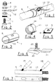
- the process involves exposing the screen conductor by practicing, by means of a grinding wheel rubber, a window in the sheath enveloping the cable, then placing the base in contact with said screen of a metal part comprising a threaded part on which are successively threaded with pre-drilled elements consisting of an adhesive sealant in mastic, a shell insulation composed of a main element and elements pre-cut to adapt the shell to the diameter of the cable, and finally a steel clamp stainless, the threaded part of the metal part being arranged to receive a connection terminal electric.
- the adhesive seal 5, the main element 8 of the shell and the clamp 11 each comprise a hole 14 allowing the passage of the threaded part of valve 1, but not of its base 15.
- the method according to the invention consists in putting bare the conductive screen by making a window 16 in the polyethylene sheath 17 enveloping the cable 9.
- a window 16 in the polyethylene sheath 17 enveloping the cable 9.
- the connector is then in place, it does not all that remains is to fix the connecting lug 12 between the two nuts 3 of the valve 1 and to close the latter by means plug 4.
- Window 16 will be made advantageously carried out by means of a tool constituted by a commercial mini-drill 18 at speed of high rotation (up to 18,000 rpm), of the type generally used for modeling.
- This drill is equipped with a grinding wheel 19 causing the heating of the cable sheath polyethylene 1 (figure 7).
- Grinding wheels made of rubber give excellent results. They cause overheating sufficient to "file” the polyethylene and remove the extrusion copolymer without damaging the aluminum constituting the conductive screen. These wheels are made of a block of cylindrical rubber or conical with rounded tip mounted on a metal rod.
- grinding wheels made of felt allow to strip the envelope, but more hardly the layer of varnish covering the screen of protection.
- the heating of the polyethylene is obtained by means of a resistance electric inserted in a nozzle of dimensions equal to the window to be produced and kept at approximately 1 cm of the envelope.
- a resistance electric inserted in a nozzle of dimensions equal to the window to be produced and kept at approximately 1 cm of the envelope.
- Valve 1 has a dual function. Besides the connection of the conductive screen, it constitutes a air intake for pressure control internal pressurized cables as well as injection of air. It is obvious that the material described can be used in cases where only this second function is operated without departing from the scope of the present invention.
- the insulating shell 7 and the adhesive seal 5 associated with its protective seal can be used for repairing a cable envelope 17. Indeed, during positioning or inside manipulations draft chambers, the cable envelope can be cut a few centimeters or deteriorated on a few square centimeters. A variant of the invention, longer (about 12 to 15 cm long) allows repair the envelope and use the cable with an internal pressure of 500 mb.
Landscapes
- Cable Accessories (AREA)
Claims (9)
- Verfahren zum Anbringen von Abdeckungen für mehrpaarigen Femleitungskabel um ihren Durchgang oder ihre Erdverbindung zu gewährleisten, bestimmt für Arbeiten vor Ort an Kabelnetzen mit leitender Schutzabschirmung, insbesondere bei druckbeaufschlagten Kabeln, in Fällen in denen der Anschluss einen Einschnitt in die äussere Kabelhülle erforderlich macht, dadurch gekennzeichnet, dass nach dem Abisolieren der leitenden Abschirmung durch Ausführen einer Öffnung (16) in der das Kabel (9) umgebenden Kabelhülle (17) aus Polyäthylen die besagte Abschirmung mit der Fussplatte eines Metallteils (1, 20) in Kontakt gebracht wird, wobei das Metallteil ein Gewindeteil aufweist, auf welches nacheinander die vorgebohrten Teile, bestehend aus einer Klebedichtung (5) aus Dichtmasse und einer Isolierschale (7), welche von einem Hauptteil (8) in Form einer Zylinderpartie und vorgestanzten Teilen (10) gebildet werden, die sich leicht durch Biegen trennen lassen und die Anpassung der Schale an den Kabeldurchmesser ermöglichen, wobei die besagte Schale von einer oder mehreren Schraubschelle(n) (11) aus rostfreiem Stahl gehalten wird, das Gewindeteil des Metallteils (1, 20) so ausgeführt ist, dass es nach Montage der Abdeckung einen Kabelschuh (12) zur elektrischen Verbindung aufnehmen kann, der mit Muttern (3) befestigt wird.
- Verfahren gemäss Anspruch 1, dadurch gekennzeichnet, dass die Klebedichtung (5) aus Dichtmasse mit einer Dichtungsscheibe oder einer Runddichtung aus Elastomer abgedeckt wird, welche sie gegen äussere Einwirkungen von chemischen Mitteln schützt.
- Verfahren gemäss irgendeinem der vorausgehenden Ansprüche, dadurch gekennzeichnet, dass die Isolierschale (7) durch eine mit einer Bohrung versehene und auf das Gewindeteil des Metallteils (1) gesteckte Schraubschelle (11) aus rostfreiem Stahl gehalten wird.
- Verfahren gemäss irgendeinem der vorausgehenden Ansprüche, dadurch gekennzeichnet, dass die Öffnung (16) mit Hilfe eines Schleifkörpers (19) aus Gummi ausgeführt wird, dazu bestimmt, eine ausreichende Erwärmung zu erzeugen, um das Polyäthylen der äusseren Hülle (17) des Kabels (9) "abzuschleifen" und das sich auf der leitenden Abschirmung befindliche Strangguss-Kopolymer zu entfernen ohne das diese Abschirmung bildende Aluminium zu beschädigen, wobei der besagte Schleifkörper aus einem auf einen Metallstift montierten zylindrischen oder konischen Gummiblock mit abgerundeter Spitze besteht.
- Verfahren gemäss Anspruch 4, dadurch gekennzeichnet, dass der Gummi-Schleifkörper (19) auf eine Kleinbohrmaschine (18), ähnlich den für den Modellbau benutzten Bohrmaschinen, montiert ist.
- Verfahren gemäss Anspruch 1, dadurch gekennzeichnet, dass die Öffnung (16) mit Hilfe eines auf einen Ansatz in der Grösse der Öffnung aufgesteckten elektrischen Heizwiderstandes ausgeführt wird, wobei das Polyäthylen nach "Erweichen" mit einem harten Gegenstand, z.B. Schraubendreher, entfernt und die auf der leitenden Abdeckung befindliche Strangguss-Kopolymerschicht mechanisch abgekratzt wird.
- Erdungsverbinder für Fernleitungskabel verwendbar für die Anwendung des Verfahrens gemäss irgendeinem der vorausgehenden Ansprüche, dadurch gekennzeichnet, dass er aus folgenden Teilen besteht:wobei die Klebedichtung (5), das Hauptteil (8) der Isolierschale und die Schraubschelle (11), wenn sie einstückig gefertigt sind, jeweils eine Bohrung (14) zur Durchführung des Gewindeteils des Metallteils (1, 20), jedoch nicht dessen Fussplatte, aufweisen.einem Metallteil (1, 20) mit einer Fussplatte und einem Gewindeteil,einer zweiseitig klebenden Dichtung (5) aus Dichtungsmasse,einer Isolierschale (7) bestehend aus einem Hauptteil (8) in Form eines Teilzylinders und dazu bestimmt, die auf dem Kabel (9) ausgeführte Öffnung abzudecken, und vorgestanzten Teilen (10) dazu bestimmt, den unteren Teil des Kabels abzudecken und die Anpassung der Isolierschale an den Kabeldurchmesser zu ermöglichen,mindestens einer Schraubschelle (11) aus rostfreiem Stahl undeinem Kabelschuh (12) befestigt mit zwei Muttern (3), mit möglicherweise angeklemmtem Erdungskabel (13),
- Verbinder gemäss Anspruch 7, dadurch gekennzeichnet, dass das Metallteil aus einem mit einer Fussplatte (15) mit flacher Sohle versehenen Ventil (1), in der Art wie es für Luftschläuche von Reifen benutzt wird, mit Dichtungsscheibe (2) und Schraubkappe (4) gebildet wird, und die Einheit durch eine mit einer Bohrung versehene über das Ventil geschobene Schraubschelle (11) gehalten wird.
- Verbinder gemäss Anspruch 7, dadurch gekennzeichnet, dass das Metallteil aus einem Stück Geflecht (20) aus verzinntem Kupfer besteht, welches in zwei Schenkel gefaltet eine Gummiplatte (21) umschliesst, die federnd zur Verstärkung des Kontaktdruckes dient, und an deren einem Ende eine Schraube (22) mit 4 mm Durchmesser geschweisst ist, wobei die Befestigung der Isolierschale (7) durch zwei Schraubschellen (11) gewährleistet wird.
Applications Claiming Priority (3)
| Application Number | Priority Date | Filing Date | Title |
|---|---|---|---|
| FR9611527A FR2753571B3 (fr) | 1996-09-17 | 1996-09-17 | Procede de raccordement des ecrans de cables de telecommunications multipaires pour assurer leur continuite ou leur mise a la terre, et materiel utilise pour realiser cette operation |
| FR9611527 | 1996-09-17 | ||
| PCT/FR1997/001626 WO1998012774A1 (fr) | 1996-09-17 | 1997-09-16 | Procede de raccordement des ecrans de cables de telecommunications multipaires pour assurer leur continuite ou leur mise a la terre, et materiel utilise pour realiser cette operation |
Publications (2)
| Publication Number | Publication Date |
|---|---|
| EP0944934A1 EP0944934A1 (de) | 1999-09-29 |
| EP0944934B1 true EP0944934B1 (de) | 2000-06-07 |
Family
ID=9495948
Family Applications (1)
| Application Number | Title | Priority Date | Filing Date |
|---|---|---|---|
| EP97919101A Expired - Lifetime EP0944934B1 (de) | 1996-09-17 | 1997-09-16 | Verfahren für die erdungskontaktierung einer fernmeldekabelabschirmung und verwendete ausrüstung |
Country Status (5)
| Country | Link |
|---|---|
| EP (1) | EP0944934B1 (de) |
| DE (1) | DE69702269T2 (de) |
| ES (1) | ES2150767T3 (de) |
| FR (1) | FR2753571B3 (de) |
| WO (1) | WO1998012774A1 (de) |
Family Cites Families (6)
| Publication number | Priority date | Publication date | Assignee | Title |
|---|---|---|---|---|
| US3346897A (en) * | 1964-08-03 | 1967-10-17 | Lockheed Aircraft Corp | Flat conductor cable stripping machine |
| US4176893A (en) * | 1977-10-25 | 1979-12-04 | General Cable Corporation | Reliable sheath bonding connector and method of making |
| US4257658A (en) * | 1979-05-07 | 1981-03-24 | Hammond Daniel L | Cable shield connector assembly |
| US4320252A (en) * | 1980-09-05 | 1982-03-16 | Western Electric Company, Inc. | Telecommunication cable closure |
| DE3915286A1 (de) * | 1989-05-10 | 1990-11-15 | August Maertens Gmbh & Co Kg | Vorrichtung zum automatischen abisolieren und verschweissen von aderleitungen |
| US5257555A (en) * | 1992-04-06 | 1993-11-02 | Teledyne Kinetics | Thermal wire stripper having a static discharge circuit |
-
1996
- 1996-09-17 FR FR9611527A patent/FR2753571B3/fr not_active Expired - Fee Related
-
1997
- 1997-09-16 ES ES97919101T patent/ES2150767T3/es not_active Expired - Lifetime
- 1997-09-16 WO PCT/FR1997/001626 patent/WO1998012774A1/fr not_active Ceased
- 1997-09-16 DE DE69702269T patent/DE69702269T2/de not_active Expired - Fee Related
- 1997-09-16 EP EP97919101A patent/EP0944934B1/de not_active Expired - Lifetime
Also Published As
| Publication number | Publication date |
|---|---|
| ES2150767T3 (es) | 2000-12-01 |
| FR2753571A1 (fr) | 1998-03-20 |
| FR2753571B3 (fr) | 1998-10-23 |
| EP0944934A1 (de) | 1999-09-29 |
| DE69702269T2 (de) | 2001-03-15 |
| DE69702269D1 (de) | 2000-07-13 |
| WO1998012774A1 (fr) | 1998-03-26 |
Similar Documents
| Publication | Publication Date | Title |
|---|---|---|
| EP0504035A2 (de) | Verbindungsvorrichtung für ein oder zwei elektrische Kabel, und Verfahren zum Montieren der Vorrichtung an das Ende des oder der Kabel | |
| FR2624665A1 (fr) | Materiau d'etancheite electrique au milieu environnant et procede d'etancheite utilisant ce materiau | |
| FR2481533A1 (fr) | Coquille protectrice pour epissures de cables entourees hermetiquement | |
| EP2255417B1 (de) | Verfahren zur beschleunigung der individuellen elektromagnetischen abschirmung eines elektrischen kabelstrangs in einem elektrischen verbinder | |
| FR2784238A1 (fr) | Ensemble electrique du type comprenant un dispositif de connexion relie a une gaine de blindage d'un cable | |
| EP0944934B1 (de) | Verfahren für die erdungskontaktierung einer fernmeldekabelabschirmung und verwendete ausrüstung | |
| EP1394900A1 (de) | Verbinder für zwei elecktrische Energiekabel und Verbindung mit einem solchen Verbinder | |
| EP0669677B1 (de) | Elektrische Verbinderanordnung für leitende Kabelabschirmung und Verfahren zu ihrer Ausführung | |
| EP0933856B1 (de) | Kaltschrumpfbare Dichtungsmuffe für elektrische Kabel | |
| EP2256890A1 (de) | Einheit zur engen Ummantelung eines länglichen Elements vorherbestimmter Grösse mit einer elastischen Schutzhülle | |
| EP0004802A1 (de) | Verfahren und Aggregat zum Montieren einer elastischen Ummantelungshülse | |
| EP0549942B1 (de) | Verbindung von elektrischen Kabeln, vormontierter Verbindungszusammenbau und Herstellungsverfahren | |
| FR2684271A1 (fr) | Dispositif et procede pour la lutte contre les nuisances avicoles et outils pour la mise en óoeuvre dudit procede. | |
| FR3137510A1 (fr) | Dispositif de raccordement électrique et son procédé de production | |
| FR2466088A1 (fr) | Procede pour proteger de facon etanche contre l'environnement l'extremite coupee de cables multiconducteurs et cables ainsi equipes | |
| EP0732768B1 (de) | Verfahren zur Herstellung einer elektrischen Verbindung mit einer metallenen Abschirmung eines Energiekabels und Ring zur Durchführung des Verfahrens | |
| EP3062407B1 (de) | Anschlussmuffe zwischen leiterkabeln, herstellungsverfahren und einbauverfahren einer solchen muffe | |
| FR2551927A1 (fr) | Dispositif de blindage electromagnetique de jonction | |
| FR2745960A1 (fr) | Dispositif de raccordement electrique permettant de connecter plusieurs cables de derivation a partir d'un cable d'arrivee | |
| FR3061810A1 (fr) | Dispositif de connexion entre les ecrans de deux elements de cable electrique | |
| FR2555372A1 (fr) | Jonction souple de raccordement de deux cables d'energie a haute tension | |
| EP0278844A1 (de) | Elektrisches Kabel, insbesondere isoliert mit getränktem Papier, an dessen Ende eine Verbindungsvorrichtung angeordnet ist | |
| EP4213322A1 (de) | Verbindungsanordnung zwischen zwei elektrischen kabeln | |
| EP1037311A1 (de) | Vorrichtung zum Abdichten einer Verbindung eines flachen Geflechts | |
| FR2537797A1 (fr) | Dispositif de jonction entre un reseau electrique souterrain et un reseau aerien |
Legal Events
| Date | Code | Title | Description |
|---|---|---|---|
| PUAI | Public reference made under article 153(3) epc to a published international application that has entered the european phase |
Free format text: ORIGINAL CODE: 0009012 |
|
| 17P | Request for examination filed |
Effective date: 19990316 |
|
| AK | Designated contracting states |
Kind code of ref document: A1 Designated state(s): DE ES FR GB IT |
|
| GRAG | Despatch of communication of intention to grant |
Free format text: ORIGINAL CODE: EPIDOS AGRA |
|
| GRAG | Despatch of communication of intention to grant |
Free format text: ORIGINAL CODE: EPIDOS AGRA |
|
| GRAH | Despatch of communication of intention to grant a patent |
Free format text: ORIGINAL CODE: EPIDOS IGRA |
|
| 17Q | First examination report despatched |
Effective date: 19991119 |
|
| GRAH | Despatch of communication of intention to grant a patent |
Free format text: ORIGINAL CODE: EPIDOS IGRA |
|
| GRAA | (expected) grant |
Free format text: ORIGINAL CODE: 0009210 |
|
| AK | Designated contracting states |
Kind code of ref document: B1 Designated state(s): DE ES FR GB IT |
|
| PG25 | Lapsed in a contracting state [announced via postgrant information from national office to epo] |
Ref country code: IT Free format text: LAPSE BECAUSE OF FAILURE TO SUBMIT A TRANSLATION OF THE DESCRIPTION OR TO PAY THE FEE WITHIN THE PRESCRIBED TIME-LIMIT;WARNING: LAPSES OF ITALIAN PATENTS WITH EFFECTIVE DATE BEFORE 2007 MAY HAVE OCCURRED AT ANY TIME BEFORE 2007. THE CORRECT EFFECTIVE DATE MAY BE DIFFERENT FROM THE ONE RECORDED. Effective date: 20000607 |
|
| REF | Corresponds to: |
Ref document number: 69702269 Country of ref document: DE Date of ref document: 20000713 |
|
| GBT | Gb: translation of ep patent filed (gb section 77(6)(a)/1977) |
Effective date: 20000823 |
|
| REG | Reference to a national code |
Ref country code: ES Ref legal event code: FG2A Ref document number: 2150767 Country of ref document: ES Kind code of ref document: T3 |
|
| PLBE | No opposition filed within time limit |
Free format text: ORIGINAL CODE: 0009261 |
|
| STAA | Information on the status of an ep patent application or granted ep patent |
Free format text: STATUS: NO OPPOSITION FILED WITHIN TIME LIMIT |
|
| 26N | No opposition filed | ||
| REG | Reference to a national code |
Ref country code: GB Ref legal event code: IF02 |
|
| PGFP | Annual fee paid to national office [announced via postgrant information from national office to epo] |
Ref country code: GB Payment date: 20020910 Year of fee payment: 6 |
|
| PGFP | Annual fee paid to national office [announced via postgrant information from national office to epo] |
Ref country code: ES Payment date: 20020925 Year of fee payment: 6 |
|
| PGFP | Annual fee paid to national office [announced via postgrant information from national office to epo] |
Ref country code: DE Payment date: 20021126 Year of fee payment: 6 |
|
| PG25 | Lapsed in a contracting state [announced via postgrant information from national office to epo] |
Ref country code: GB Free format text: LAPSE BECAUSE OF NON-PAYMENT OF DUE FEES Effective date: 20030916 |
|
| PG25 | Lapsed in a contracting state [announced via postgrant information from national office to epo] |
Ref country code: ES Free format text: LAPSE BECAUSE OF NON-PAYMENT OF DUE FEES Effective date: 20030917 |
|
| PG25 | Lapsed in a contracting state [announced via postgrant information from national office to epo] |
Ref country code: DE Free format text: LAPSE BECAUSE OF NON-PAYMENT OF DUE FEES Effective date: 20040401 |
|
| GBPC | Gb: european patent ceased through non-payment of renewal fee |
Effective date: 20030916 |
|
| PGFP | Annual fee paid to national office [announced via postgrant information from national office to epo] |
Ref country code: FR Payment date: 20040909 Year of fee payment: 9 |
|
| REG | Reference to a national code |
Ref country code: ES Ref legal event code: FD2A Effective date: 20030917 |
|
| PG25 | Lapsed in a contracting state [announced via postgrant information from national office to epo] |
Ref country code: FR Free format text: LAPSE BECAUSE OF NON-PAYMENT OF DUE FEES Effective date: 20060531 |
|
| REG | Reference to a national code |
Ref country code: FR Ref legal event code: ST Effective date: 20060531 |