EP0944404B1 - Durchflussregelsystem mit wegwerfbarerpumpenkassette - Google Patents
Durchflussregelsystem mit wegwerfbarerpumpenkassette Download PDFInfo
- Publication number
- EP0944404B1 EP0944404B1 EP97910935A EP97910935A EP0944404B1 EP 0944404 B1 EP0944404 B1 EP 0944404B1 EP 97910935 A EP97910935 A EP 97910935A EP 97910935 A EP97910935 A EP 97910935A EP 0944404 B1 EP0944404 B1 EP 0944404B1
- Authority
- EP
- European Patent Office
- Prior art keywords
- cartridge
- fluid flow
- body portion
- housing
- fluid
- Prior art date
- Legal status (The legal status is an assumption and is not a legal conclusion. Google has not performed a legal analysis and makes no representation as to the accuracy of the status listed.)
- Expired - Lifetime
Links
Images


Classifications
-
- A—HUMAN NECESSITIES
- A61—MEDICAL OR VETERINARY SCIENCE; HYGIENE
- A61M—DEVICES FOR INTRODUCING MEDIA INTO, OR ONTO, THE BODY; DEVICES FOR TRANSDUCING BODY MEDIA OR FOR TAKING MEDIA FROM THE BODY; DEVICES FOR PRODUCING OR ENDING SLEEP OR STUPOR
- A61M1/00—Suction or pumping devices for medical purposes; Devices for carrying-off, for treatment of, or for carrying-over, body-liquids; Drainage systems
- A61M1/71—Suction drainage systems
- A61M1/77—Suction-irrigation systems
-
- A—HUMAN NECESSITIES
- A61—MEDICAL OR VETERINARY SCIENCE; HYGIENE
- A61M—DEVICES FOR INTRODUCING MEDIA INTO, OR ONTO, THE BODY; DEVICES FOR TRANSDUCING BODY MEDIA OR FOR TAKING MEDIA FROM THE BODY; DEVICES FOR PRODUCING OR ENDING SLEEP OR STUPOR
- A61M1/00—Suction or pumping devices for medical purposes; Devices for carrying-off, for treatment of, or for carrying-over, body-liquids; Drainage systems
- A61M1/71—Suction drainage systems
- A61M1/72—Cassettes forming partially or totally the fluid circuit
-
- A—HUMAN NECESSITIES
- A61—MEDICAL OR VETERINARY SCIENCE; HYGIENE
- A61M—DEVICES FOR INTRODUCING MEDIA INTO, OR ONTO, THE BODY; DEVICES FOR TRANSDUCING BODY MEDIA OR FOR TAKING MEDIA FROM THE BODY; DEVICES FOR PRODUCING OR ENDING SLEEP OR STUPOR
- A61M3/00—Medical syringes, e.g. enemata; Irrigators
- A61M3/02—Enemata; Irrigators
- A61M3/0201—Cassettes therefor
-
- A—HUMAN NECESSITIES
- A61—MEDICAL OR VETERINARY SCIENCE; HYGIENE
- A61M—DEVICES FOR INTRODUCING MEDIA INTO, OR ONTO, THE BODY; DEVICES FOR TRANSDUCING BODY MEDIA OR FOR TAKING MEDIA FROM THE BODY; DEVICES FOR PRODUCING OR ENDING SLEEP OR STUPOR
- A61M1/00—Suction or pumping devices for medical purposes; Devices for carrying-off, for treatment of, or for carrying-over, body-liquids; Drainage systems
- A61M1/71—Suction drainage systems
- A61M1/74—Suction control
-
- A—HUMAN NECESSITIES
- A61—MEDICAL OR VETERINARY SCIENCE; HYGIENE
- A61M—DEVICES FOR INTRODUCING MEDIA INTO, OR ONTO, THE BODY; DEVICES FOR TRANSDUCING BODY MEDIA OR FOR TAKING MEDIA FROM THE BODY; DEVICES FOR PRODUCING OR ENDING SLEEP OR STUPOR
- A61M1/00—Suction or pumping devices for medical purposes; Devices for carrying-off, for treatment of, or for carrying-over, body-liquids; Drainage systems
- A61M1/80—Suction pumps
-
- A—HUMAN NECESSITIES
- A61—MEDICAL OR VETERINARY SCIENCE; HYGIENE
- A61M—DEVICES FOR INTRODUCING MEDIA INTO, OR ONTO, THE BODY; DEVICES FOR TRANSDUCING BODY MEDIA OR FOR TAKING MEDIA FROM THE BODY; DEVICES FOR PRODUCING OR ENDING SLEEP OR STUPOR
- A61M2205/00—General characteristics of the apparatus
- A61M2205/12—General characteristics of the apparatus with interchangeable cassettes forming partially or totally the fluid circuit
-
- A—HUMAN NECESSITIES
- A61—MEDICAL OR VETERINARY SCIENCE; HYGIENE
- A61M—DEVICES FOR INTRODUCING MEDIA INTO, OR ONTO, THE BODY; DEVICES FOR TRANSDUCING BODY MEDIA OR FOR TAKING MEDIA FROM THE BODY; DEVICES FOR PRODUCING OR ENDING SLEEP OR STUPOR
- A61M2205/00—General characteristics of the apparatus
- A61M2205/33—Controlling, regulating or measuring
- A61M2205/3331—Pressure; Flow
- A61M2205/3351—Controlling upstream pump pressure
-
- A—HUMAN NECESSITIES
- A61—MEDICAL OR VETERINARY SCIENCE; HYGIENE
- A61M—DEVICES FOR INTRODUCING MEDIA INTO, OR ONTO, THE BODY; DEVICES FOR TRANSDUCING BODY MEDIA OR FOR TAKING MEDIA FROM THE BODY; DEVICES FOR PRODUCING OR ENDING SLEEP OR STUPOR
- A61M2205/00—General characteristics of the apparatus
- A61M2205/60—General characteristics of the apparatus with identification means
- A61M2205/6045—General characteristics of the apparatus with identification means having complementary physical shapes for indexing or registration purposes
-
- Y—GENERAL TAGGING OF NEW TECHNOLOGICAL DEVELOPMENTS; GENERAL TAGGING OF CROSS-SECTIONAL TECHNOLOGIES SPANNING OVER SEVERAL SECTIONS OF THE IPC; TECHNICAL SUBJECTS COVERED BY FORMER USPC CROSS-REFERENCE ART COLLECTIONS [XRACs] AND DIGESTS
- Y10—TECHNICAL SUBJECTS COVERED BY FORMER USPC
- Y10S—TECHNICAL SUBJECTS COVERED BY FORMER USPC CROSS-REFERENCE ART COLLECTIONS [XRACs] AND DIGESTS
- Y10S128/00—Surgery
- Y10S128/12—Pressure infusion
Definitions
- the present invention pertains to the fluid pumping art and, more specifically, to a fluid flow system incorporating a control module to which is removably attached a disposable pump cartridge that defines an internal fluid flow circuit.
- the system is particularly applicable for use in a surgical procedure requiring a controlled pressure and/or flow rate of a fluid either delivered to or withdrawn from a patient, thereby exposing the fluid flow circuit to possible contaminants.
- pumping devices are required that need only produce rather low flow rates but which cannot be reused without being thoroughly cleaned between uses.
- various bodily fluids may need to be delivered to and withdrawn from a patient.
- a pumping device used for this purpose will obviously be exposed to these fluids.
- the pumping device and other exposed system components will either have to be discarded or, in some way, sanitized prior to subsequent use.
- the associated pumping rates for these systems are rather low such that the pumping devices can be made fairly small, the cost associated with manufacturing these pumping devices and other exposed system components is still quite high and therefore disposing of such these components following a single use would be quite costly.
- cleaning and sterilizing these components for later use can also be costly, as well as time consuming.
- Some fluid flow control systems also must provide for the flow of numerous fluids. For example, during eye surgery, it is common to supply an irrigation fluid to the surgical site while withdrawing or aspirating additional, fluid suspended material from the site. During such a procedure, it is imperative to properly control the flow of fluids to maintain a proper intraocular environment. Major fluctuations in intraocular pressure can occur if a proper fluid balance is not maintained during irrigation and aspiration, either alone or during a phacoemulsification procedure. Perhaps most important is aspiration control as this is responsible for maintaining the shape of the anterior chamber throughout the surgery.
- Various pumping systems including peristaltic and venturi-based systems, are commonly used in the art to perform such eye operations.
- controlling the flow rate and/or pressure from the surgical site is critical.
- the surgeon generally controls the system, typically through a foot pedal unit, additional sensory equipment is being more commonly provided to regulate system flow rates and/or pressures.
- this sensory equipment further adds to the cost of such systems and potentially adds to the number of components that must be sanitized between uses.
- a disposable cartridge according to the invention allows a versatile and cost effective fluid flow control system to be provided which is particularly adapted for use in environments requiring rather low flow rates (generally less than 60 ml/min) and which will have portions that will be exposed to potential contaminants.
- the fluid flow control system includes the disposable cartridge which is defined by a housing within which is mounted a pump constitued by a miniature scroll fluid device, and a pressure transducer element.
- the cartridge housing has numerous external connection ports for attaching tubes from a fluid supply source, an output fluid conduit, a contaminated fluid intake line and a reservoir.
- a separating member in the form of an elastomeric sheet is positioned in the cartridge housing and defines, along with open channels formed on an inner surface of one section of the cartridge housing, a plurality of flow passages which collectively define a fluid flow circuit that is in fluid communication with each of the external connection ports, as well as inlet and outlet ports for each of the pump and pressure transducer element.
- the fluid flow control system also includes a control module for supporting the disposable cartridge during system operation and for regulating fluid flow through the fluid flow circuit.
- the control module includes a control housing having a main body portion and a carrier body portion that is shiftable, through a mechanism carried by the main body portion, relative to the main body portion between a cartridge loading/unloading position and a system in-use position.
- the control module incorporates a plurality of linearly shifting valve members, a re-usable transducer element and a pump driveshaft that are automatically interengaged with portions of the disposable cartridge following loading and shifting of the carrier body portion.
- the disposable cartridge contains, or has fluidly connected thereto, all of the system components which can become contaminated during use.
- a system user need only place a new cartridge in the carrier body portion to cause the cartridge to be operatively interconnected to the control module and then connect the required tubes or conduits to the external connection ports.
- Flow within and through the cartridge will be regulated by the extension and retraction of the valve members which can engage the elastomeric sheet and, in combination with the cartridge housing, pinch the sheet to cause flow regulation at selected points in the fluid flow circuit.
- flow through the system can be selectively controlled based on operator inputs and selected parameters of system pressure, flow rate or both.
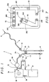
- Fluid flow circuit 2 includes a first tubular passageway 4 that is adapted to receive a supply of irrigation fluid, such as saline, that is received within first tubular passageway 4 through a supply inlet zone 6.
- First tubular passageway 4 terminates in a discharge nozzle 8, the position of which is controlled by a surgeon or other operating attendant for irrigation purposes.
- a first valve control point 10 is defined. As will be described more fully below, first valve control point 10 establishes a predetermined location within first tubular passageway 4 where the flow of fluid therethrough can be controlled.
- Fluid flow circuit 2 also includes a second tubular passageway 13 including an intake nozzle 16 at one end thereof.
- intake nozzle 16 and second tubular passageway 13 are used for aspiration purposes.
- second tubular passageway 13 Remote from intake nozzle 16, second tubular passageway 13 is attached to an inlet port 18 of a pressure transducer 20.
- second valve control point 24 is defined along second tubular passageway 13.
- Second tubular passageway 13 may be interconnected through a vent line 27 to first tubular passageway 4. As represented in this Figure, vent line 27, if provided, would have associated therewith a third valve control point 29.
- Pressure transducer 20 has an outlet 32 that is connected to an inlet port 34 of a pump 36.
- pump 36 is constituted by a miniature scroll fluid device having an output flow rate ranging in the order of 1 ml/min to 60 ml/min, at a maximum vacuum pressure of approximately 550 mm Hg.
- Pump 36 has associated therewith a discharge port 38 that is in fluid communication with a reservoir 41.
- Outlet 32 of pressure transducer 20 is also connected to a first end 43 of a calibration conduit 45.
- Calibration conduit 45 includes a second end 47 that also discharges into reservoir 41.
- a normally closed pressure calibration valve indicated at 49 Located within calibration conduit 45, between first and second ends 43 and 47, is a normally closed pressure calibration valve indicated at 49.
- Calibration conduit 45 and its associated valve 49 are merely included for the sake of completeness and can be used to calibrate pressure transducer 20, however, since this is not considered an essential feature of the present invention as pressure transducer 20 may not require such calibration.
- a major aspect of the present invention concerns integrating the structural components of fluid flow circuit 2 into an assembly that can be made in a compact and economically viable manner. Since the components of fluid flow circuit 2 represent all of the structure that will be subjected to potentially contaminated fluids during the surgical operation, incorporating these components into an integrated assembly will not only enable the components to be readily isolated from other system components which need not be directly exposed to the various fluids flowing through circuit 2, but can provide for the efficient replacement of a used assembly and disposal thereof following a single use as will become more fully apparent below.
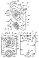
- Disposable cartridge 52 includes a first housing section 54 and a second housing section 56 that are adapted to be attached together along a circumferential joint 58.
- first and second housing sections 54 and 56 are molded of plastic and are joined at joint 58 through a welding operation.
- other attachment arrangements including mechanical fasteners or adhesive could be utilized.
- first housing section 54 includes an outer surface 60 that is generally rectangular in shape but which is provided with a semi-circular lower extension 62. Spaced from semi-circular lower extension 62, outer surface 60 of first housing section 54 is formed with a bore 64 and, formed at a top section of first housing 54 are first, second, third and fourth external connection ports 66-69.
- each external connection port 66-69 is defined by a respective upstanding, generally cylindrical member 71-75 having a central bore 76-79.
- External connection ports 66-69 are adapted to be interconnected to tubes or other fluid conduits (not shown) that are interconnected to disposal cartridge 52 to complete fluid flow circuit 2. To assure the proper connections by preventing potential human error in completing the circuit, in the preferred embodiment, external connection ports 66-69 have different sizes which correspond to the sizes of the respective conduits to be attached thereto.
- Second external connection port 67 is actually defined by cylindrical member 72 which constitutes an inner cylindrical member and an outer cylindrical member 82 which are spaced by an annular gap 85 as clearly shown in Figure 4.
- Each of external connection ports 66, 68 and 69 are adapted to have tubular conduits fit about their respective cylindrical members 71, 73 and 74 while a conduit is adapted to be inserted within annular gap 85 and about inner cylindrical member 72 of second external connection port 67 to be placed in fluid communication with central bore 77.
- outer surface 60 is also formed with a pair of spaced suspension members 88 and 89 which, as will be more fully discussed below, are provided for suspending a pouch or other container (not shown) that defines reservoir 41 from disposable cartridge 52.
- suspension members 88 and 89 each includes an outwardly projecting portion 91 and an upstanding tab portion 93.
- the pouch is preferably provided with spaced apertures for use in hanging the pouch from suspension members 88 and 89.
- First housing section 54 has an inner surface 95 as best shown in Figure 5.
- Inner surface 95 is formed with a pair of boxed-shaped openings 96 at suspension members 88 and 89, an inner annular ledge 99 which extends about the entire inner periphery of first housing section 54 and a plurality of open channels generally indicated at 102 and 103.
- Channels 102 and 103 are actually defined by raised wall portions 104 of inner surface 95.
- open channel 102 includes a first end 106 that extends along a top wall portion 108 of first housing section 54, downward along side wall portion 110 and then terminates at a second end 112 adjacent bore 64.
- Open channel 103 has a first end 114 arranged adjacent bore 64 and is thereafter divided into subchannels 116 and 117 having respective terminal ends 118 and 119.
- open channel 102 is formed with first, second and third holes 121-123 at top wall portion 108 and open channel 103 is formed with a fourth hole 124 at terminal end 119.
- Holes 121-124 are actually defined by central bores 76-79 of external connection ports 66-69 and therefore channels 102 and 103 are open external to disposable cartridge 52.
- inner surface 95 of first housing section 54 is preferably provided with a plurality of reinforcing ribs, one of which is indicated at 126.
- second housing section 56 includes an outer surface 129 having an upper recessed section 132 defined by an inwardly tapering, annular wall 134 that leads to a base 136. Radially inwardly of base 136 is an upwardly extending and inwardly tapering wall 138 that leads to a central annular ledge 139 that is provided with an opening 140. Spaced below recessed section 132, second housing 56 is provided with a lower opening 143 that defines an inner, annular seating surface 145. Outer surface 129 is further provided with various spaced apertures 147-150 that extend entirely through second housing section 56.
- second housing section 56 has an inner surface 152 from which project numerous upstanding interior wall members 154-160. Upstanding interior wall members 154-I56 perform structural integrity and valve member guiding functions as will become more clearly evident hereinafter when considered in connection with the type of valving incorporated in the preferred embodiment. At this point, however, it should be realized that apertures 147 and 148 are located between a top wall 161 of second housing section 56 and wall member 154, aperture 149 is arranged between a side wall (not labeled) of second housing section 56 and wall member 155, and aperture 150 is positioned between an opposing side wall (not labeled) of second housing section 56 and wall member 159.
- Upstanding interior wall member 154 is preferably formed with a depending detent member 162 which, as will be described more fully below, provides an alignment and mounting aid for pump 36.
- base 136 of recessed section 132 defines a raised surface 164 from which extends an annular wall 167 having an upper rim 168 that is formed with a groove 169.
- Groove 169 is adapted to receive an O-ring (not shown) for use in sealing against a portion of pump 36.
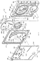
- Elastomeric sheet 177 is extremely flexible and pliable and includes a first side 179 formed with numerous upstanding sealing walls 181 which are adapted to be sealingly mated with the raised wall portions 104 of channels 102 and 103 to define plural fluid flow passages. More specifically, upstanding sealing walls 181 of elastomeric sheet 177 define an upper channel 183 that leads to a side channel 185 and a bottom channel portion 187. Bottom channel portion 187 terminates at a wall 189 formed about an opening 190. In addition, upstanding sealing walls 181 defines a further bottom channel portion 191 that is bifricated by means of an upstanding wall 193 into subchannel portions 195 and 196.
- Elastomeric sheet 177 is also provided with a plurality of through holes 197-200. More specifically, a first through hole 197 is provided in bottom channel portion 187 adjacent terminal wall 189, a second through hole 198 is provided in bottom channel portion 191 adjacent wall 189, and third and fourth through holes 199 and 200 are provided at terminal ends of subchannel portions 195 and 196 respectively. On the second side 201 of elastomeric sheet 177, each of through holes 197-200 has associated therewith upstanding sealing rings 204-207 respectively.
- scroll fluid device 211 includes a pair of meshing scroll elements 214 and 216.
- first and second scroll elements 214 and 216 have internally meshed involute spiral wrap members that define at least one fluid chamber that moves radially from a pump inlet zone to a pump outlet zone when one of the wrap members is orbited along a circular path about an orbit center relative to the other of the wrap members.
- first scroll element 214 includes an exposed side 217 that is formed with a central hub 218 provided with a bore 220.
- Second scroll element 216 includes a flange 226 that extends radially outwardly of first scroll element 214.
- Flange 226 includes a peripheral edge 228 that is formed with an upstanding ledge 230 having a central notch 232.
- second scroll element 216 has an exposed side 235 that is formed with a pair of spaced annular recesses 236 and 238 that define central upstanding connectors 240 and 241. Upstanding connectors 240 and 241 actually define outlet and inlet ports for scroll fluid device 211.
- pressure transducer element 244 that actually constitutes part of an overall pressure transducer assembly.
- pressure transducer element 244 includes an outer shell 247 preferably formed of plastic to which is sealed a deflectable diaphragm 249 that is preferably formed of stainless steel.
- Shell 247 is formed with a central locating projection 252, as well as a pair of diametrically opposed fluid flow connectors 255 and 256 which constitute inlet and outlet ports for pressure transducer 244 to enable the flow of system fluid therethrough.
- first and second housing sections 54 and 56 of disposable cartridge 52 are adapted to be interconnected with elastomeric sheet 177, scroll fluid device 211 and pressure transducer element 244 disposed therein.
- elastomeric sheet 177 is preferably adhesively secured to inner surface 95 of first housing section 54 such that elastomeric sheet 177 sealingly extends across open channels I02 and 103 such that these channels define sealed fluid flow passages open only at holes 121-124 and through holes 197-200.
- upstanding sealing walls 181 of elastomeric sheet 177 are actually received within a continuous groove 260 formed about open channels 102 and 103.
- Scroll fluid device 211 is positioned within second housing section 56 with annular groove 222 being seated upon raised surface 164 and central hub 218 projecting into opening 140.
- Central hub 218 has a smaller diameter than opening 140 to permit the unobstructed orbital movement of first scroll element 214 during operation of scroll fluid device 211.
- Second scroll element 216 is also seated within second housing section 56 with flange 226 being sealed thereto by means of the O-ring positioned within groove 169 and upstanding ledge generally abutting upstanding interior wall member 154.
- notch 232 provided on second scroll element 216 receives detent member 162 to aid in the aligning and mounting of scroll fluid device 211.
- Pressure transducer 244 is positioned in lower opening 143 with diaphragm 249 being exposed at outer surface 129 of second housing section 56.
- connectors 255 and 256 of pressure transducer element 244 are mated with upstanding sealing rings 204 and 205 of elastomeric sheet 177 while central locating projection 252 extends through opening 190 and into bore 64.
- upstanding sealing rings 206 and 207 of elastomeric sheet 177 are interconnected with central upstanding connectors 240 and 241 of scroll fluid device 211.
- scroll fluid device 211 is sealingly mounted within disposable cartridge 52 and has one port (an inlet port in the preferred embodiment disclosed) fluidly connected with the flow passage defined by the combination of open subchannel 118 and elastomeric sheet 177 through the use of the upstanding sealing ring 207.
- connector 240 which defines an outlet for scroll fluid device 211 is connected through upstanding sealing ring 206 to subchannel 117 at fourth hole 124.
- fourth hole 124 leads to connection port 69.
- a reservoir 41 in the form of a pouch is adapted to be suspended from suspension members 88 and is connected to port 69 such that the output from scroll fluid device 211 leads to reservoir 41.
- the inlet and outlet of pressure transducer element 244 are also in fluid communication with the fluid passages defined by open channels 102 and 103 and elastomeric sheet 177 through connectors 255 and 256 and first and second through holes 197 and 198.
- Upstanding sealing rings 204 and 205 provide for a complete seal in this fluid communication.
- the disposable cartridge establishes the overall fluid flow circuit generally indicated at 2 in Figure 1.
- This is perhaps best represented schematically in Figure 7 wherein at least fluid passages 261-263 are established with fluid passage 261 receiving a supply of fluid (for irrigation purposes in the embodiment disclosed) at point 264; an outlet supply of irrigating fluid is provided at 265; an input flow of aspirated fluid (perhaps with suspended particles therein) is placed in fluid communication with flow passage 261 at reference numeral 266; fluid is permitted to flow to pressure transducer element 244 from fluid passage 261 at location 267; flow exits pressure transducer element 244 at location 268; inlet fluid to scroll fluid device 211 occurs at point 269 and point 270 represents an output to reservoir 41.
- valve point locations represent zones wherein elastomeric sheet 177 is pinched such that it extends within a respective portion of fluid flow passages 261 and 263 to selectively control the flow of fluid through these passages. Since elastomeric sheet 177 is formed of a flexible and pliable material, the sheet material itself is actually utilized to perform the valving function, in combination with valve elements used to deflect the sheet as will be more fully described below.
- disposable cartridge 52 provides for an integrated assembly of components, as well as an internal fluid flow circuit to which only a few fluid flow connections need be made at connection ports 66-69 to complete the overall circuit. It should also be evident that these external connection ports 66-69 directly correspond to the tube attaching locations discussed above with reference to numbers 264, 265, 266 and 270 respectively.
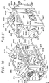
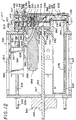
- control module 277 includes a main body portion 279 and a carrier body portion 281.
- Carrier body portion 281 includes a front panel 284, side panels 286 and 287, a bottom panel 289, a central panel 291, a top panel portion 293 and a rear plate 295 as best shown in Figures 8 and 12.
- carrier body portion 281 is made of metal with rear plate 295 being made of aluminum and the remainder of carrier body portion 281 being formed of sheet metal.
- carrier body portion 281 defines a cartridge receiving area or slot 298 which, as will be discussed more fully below, is adapted to receive disposable cartridge 52.
- front panel 284 includes a lower opening 300 across which is positioned a spring member 301 having at least one biasing finger 303 (not shown in Figure 8 for clarity, but see Figures 9, 10 and 12) that has an arcuate terminal end 305.
- Central panel 291 and rear plate 295 include a pair of aligned and spaced upper apertures 307 and 308. Actually, central panel 291 and rear plate 295 are provided with four such apertures, the other two of which are arranged below central panel 291. The location and purpose of each of these additional apertures will become readily apparent hereinafter.
- Central panel 291 is also formed with a central opening 312 about which are spaced a plurality of arcuate slots 314-317.
- Central panel 291 and rear plate 295 further define a lower rear opening 319 formed in carrier body portion 281.
- rails 322-325 are slidably supported by main body portion 279 and function to guide carrier body portion 281 during relative shifting movement between carrier body portion 281 and main body portion 279.
- main body portion 279 includes a base plate 327, a front plate 328, a rear plate 329, a top plate 330 and at least one side plate 331.
- plates 327-331 are formed from aluminum and are interconnected together with conventional mechanical fasteners (not shown).
- Adjacent each of the corners of front and rear plates 328 and 329 are defined respective front and rear aligned holes 334 and 335 having positioned therein a respective bushing 337 preferably formed of plastic.
- each bushing 337 Within each bushing 337 extends a respective guide rail 322-325.
- guide rails 322-325 each include a respective end portion 340 that extends outward beyond rear plate 329.
- carrier body portion 281 is slidably supported by main body portion 279 through guide rails 322-325 with carrier body portion 281 being movable towards and away from front plate 328 at least a distance defined by the length of end portions 340.
- movement of carrier body portion 281 relative to main body portion 279 enables carrier body portion 281 to assume an extended, cartridge loading/unloading position as shown in Figure 9 and an in-use position as shown in Figures 10 and 12.
- Mechanism 342 is preferably constituted by a bi-directional, linear electric motor 343 having an associated longitudinally shiftable shaft 345 that extends through an opening 347 provided in rear plate 329 and a bushing 349 provided in a hole 350 provided in front plate 328.
- the forward end 352 of shaft 345 is attached, for relative rotation, to rear plate 295 of carrier body portion 281.
- activation of linear motor 343 causes shaft 345 to rotate, such as through a helical or worm gear drive, such that shaft 345 is shifted linearly relative to main body portion 279.
- mechanism 342 constitutes a linear motor and mechanical drive arrangement in the preferred embodiment, various other types of linear drive systems could be utilized, including solenoid, pneumatic and hydraulic actuators, without departing from the spirit of the invention.
- Main body portion 279 also has mounted therein a pump drive motor 355 that includes an encased housing 356 having an output driveshaft 357. As best shown in Figure 12, output driveshaft 357 has drivingly connected thereto a connector 358 having an inner connector element 359 and an outer connector element 360. Outer connector element 360 includes a flared portion 36I .
- drive connector 358 actually constitutes an eccentric bushing used to transmit drive to scroll fluid device 211. More specifically, outer connector element 360 is adapted to be received within central hub 218 of first scroll element 214 for driving scroll fluid device 21 upon loading of disposable cartridge 52 in the manner which will be detailed below.
- Pump drive motor 355 actually includes a forward housing portion 362 that is mounted to a center section 363 of an alignment bushing 364.
- Center section of alignment bushing 364 actually includes a first diametric portion 365 and a second, reduced diametric portion 367 and forward end 362 of pump drive motor 355 abuts second, reduced diametric portion 367 and is fixed to first diametric portion 365 as clearly shown in Figure 12.
- Alignment bushing 364 itself is fixed in an opening 368 provided in front plate 328.
- Alignment bushing 364 has a forwardly projecting inner cylindrical sleeve 369 and an outer cylindrical sleeve 371 having various, circumferentially spaced cut-out sections 372-375.
- Inner cylindrical sleeve 369 is aligned with central opening 312 and the various sections of outer cylindrical sleeve 371 are respectively aligned with arcuate slots 314-317.
- outer cylindrical sleeve 371 has a tapered front edge 376 as best shown in Figure 12.
- Main body portion 279 also supports a fixed pressure transducer element 377.
- fixed pressure transducer element 377 includes a vacuum tube portion 378 having an enlarged diametric head 380 and an annular flange 382.
- Fixed pressure transducer element 377 is fixedly secured to front plate 328 through annular flange 382 and has a front terminal seat 384 having an O-ring 386 against which pressure transducer element 244 is seated when disposable cartridge 52 is placed within carrier body portion 281 and carrier body portion 281 is moved to its in-use position as shown in Figure 12.
- Fixed pressure transducer element 377 further includes a sensing unit indicated at 387 which is adapted to be positioned juxtaposed to diaphragm 249 to sense the deflections of diaphragm 249 based on its exposure to fluid system pressures. Although not shown in these drawings for the sake of clarity, fixed pressure transducer element 377 also incorporates electronic control components within tube 378 to receive signals from sensor unit 387 for use in determining the fluid system pressure in fluid flow circuit 2 based on the sensed movement of diaphragm 249. As indicated above, various different types of known transducer assemblies can be utilized to perform the desired pressure sensing function in accordance with the present invention
- valve unit 389 constitutes a solenoid valve and therefore includes a solenoid housing 391 which is fixed within main body portion 279 such as through the use of a generally U-shaped bracket 393 that has a base 395 secured to front plate 328 and leg portions 397 and 398 that are attached to solenoid housing 391 by means of a plurality of fasteners 399.
- Each valve unit 389 includes a linearly shifting valve member 401 in the form of a rod having a tapering tip 405.
- Each valve member 401 is slidably mounted within a guide sleeve 407 that extends through a respective bore 409 formed in front plate 328.
- four such solenoid valve units 389 are provided, each of which has an associated valve member 401 extending through front plate 328 and which can be linearly shifted.
- the tapered tip 405 of each valve member 401 is adapted to extend through a respective one of the apertures discussed above with reference to apertures 307 and 308 formed in carrier body portion 281 and then into disposable cartridge 52 at apertures 147-150 respectively.
- tapered tips 405 can engage elastomeric sheet 177 at first, second, third and fourth valve control points 10, 24, 29 and 49 respectively. Additional details regarding the operation of each valve unit 389 will now be discussed in describing the manner in which the fluid flow control system of the present invention operates.
- control module 277 When preparing for a surgical procedure, control module 277 would initially assume the loading/unloading position illustrated in Figure 9. Of course, main body portion 279 would have some sort of outer covering which is not shown in order to detail the internal structure of control module 277. In any event, in this position, carrier body portion 281 is spaced from main body portion 279 yet supported through guide rails 322-325. In this position, alignment bushing 364 and the valve member 104 of each valve unit 389 is clear of cartridge receiving area 298. As mentioned above, carrier body portion 281 can be shifted to this loading/unloading position by means of linear motor 343 and the connection of shaft 345 to rear plate 295. As clearly shown, drive connector 358 is also spaced from cartridge receiving area 298.
- a new disposable cartridge 52 can be readily placed within cartridge receiving area 298 with central locating projection 252 of pressure transducer element 244 being positioned against finger 303 of spring member 301 and external connection ports 66-69 extending above front panel 284 of carrier body portion 281.
- a reservoir bag would be attached to disposable cartridge 52 at suspension members 88 and 89, as well as to fourth connection port 69, prior to insertion of disposable cartridge 52 within cartridge receiving area 298.
- the reservoir assembly could equally be attached anytime prior to system start-up.
- cartridge 52 Once disposable cartridge 52 is in place, an operator would press a button (not shown) which actuates linear motor 343 and causes carrier body portion 281 to be drawn towards main body portion 279 such that control module 277 assumes the in-use position (shown in Figures 10 and 11 without cartridge 52 and in Figure 12 with cartridge 52 in place). Alternatively, cartridge 52 could engage a switch when inserted in cartridge receiving area 298 to automatically cause the shifting of carrier body portion 281.
- pump drive motor 355 can be controlled to operate scroll fluid device 211 to create a suction at third connection point 68 through flow passage 262, pressure transducer element 244 and fluid passage 261.
- fluid drawn in from the operation of scroll fluid device 211 is directly delivered to reservoir 41 as the output of scroll fluid device 211 is in direct flow communication with external connection port 69 by means of through hole 199 in elastomeric sheet 177.
- Calibration valve 49 is normally closed which, in the embodiment disclosed, occurs by extending a respective valve member 401 such that the tapered tip 405 thereof pinches elastomeric sheet 177 and causes the same to obstruct flow through fluid passage 263.
- valve control can also be provided at first, second and third valve control points 10, 24 and 29.
- irrigation irrigation is desired, flow is readily permitted within flow passage 261 whereby first and second external connection ports 66 and 67 are placed in fluid communication with each other (i.e., fluid is permitted to freely flow between points 264 and 265 as shown in Figure 7).
- first and second external connection ports 66 and 67 are placed in fluid communication with each other (i.e., fluid is permitted to freely flow between points 264 and 265 as shown in Figure 7).
- vent line 27 is normally closed, the valve member 401 associated with third valve control point 29 is normally, fully extended.
- pump drive motor 355 and valve units 389 during use of the fluid flow control system of the present invention is actually electronically controlled in accordance with the preferred embodiment. More specifically, as shown in Figure 13, an electronic control unit 417 is provided which receives inputs from an operator control member (such as a foot pedal) indicated at 420, a manual operating mode control switch 422 and signals from the sensing unit 387. Electronic control unit 417 utilizes these signals to output control signals to each of pump drive motor 355, linear motor 343 and valve units 389.
- Foot pedal controller 420 is constructed in accordance with those known in the prior art and enables a surgeon to control the irrigation and aspiration as needed.
- Operating mode control switch 422 can be used to select whether control module 277 provides an established aspiration flow rate, a controlled aspiration vacuum pressure or both. If a flow rate based system is desired, operating mode control switch 422 would be appropriately set and pump drive motor 355 would be accordingly controlled in a manner similar to known peristaltic type systems. On the other hand, operating mode control switch 422 can be positioned in a vacuum-based operating mode wherein electronic control unit 417 would operate pump drive motor 355 based on signals not only received from foot pedal 420 but also from sensing unit 387 associated with fixed pressure transducer element 377. In this mode, control module 277 would function in a manner analogous to known venturi type systems.
- electronic control unit 417 When operating in a pressure-based mode, electronic control unit 417 would be configured to shut down if an obstruction was presented in the aspiration line which increased system pressure beyond a threshold value. In addition, when operating in a flow rate mode, electronic control unit would also be sensitive to high RPM increases resulting from a possible obstruction in the aspiration line since such a high RPM increase could lead to a surge in the suction after the obstruction is removed. In this mode, electronic control unit 417 would therefore still be sensitive to pressure signals to avoid this potential problematic situation.
Landscapes
- Health & Medical Sciences (AREA)
- Heart & Thoracic Surgery (AREA)
- Animal Behavior & Ethology (AREA)
- General Health & Medical Sciences (AREA)
- Anesthesiology (AREA)
- Biomedical Technology (AREA)
- Hematology (AREA)
- Life Sciences & Earth Sciences (AREA)
- Veterinary Medicine (AREA)
- Engineering & Computer Science (AREA)
- Public Health (AREA)
- Vascular Medicine (AREA)
- Pulmonology (AREA)
- External Artificial Organs (AREA)
- Infusion, Injection, And Reservoir Apparatuses (AREA)
- Reciprocating Pumps (AREA)
- Feeding And Controlling Fuel (AREA)
Claims (12)
- Wegwerfbare Kassette (52) zur Verwendung in einem Durchflussregelsystem, mit
einem aus mindestens zwei zusammengefügten Gehäuseabschnitten (54, 56) gebildeten Kassettengehäuse, wobei die Gehäuseabschnitte (54, 56) mit mindestens zwei Fluidanschlussstutzen (66-69), einem mit den Anschlussstutzen strömungsverbundenen inneren Durchflusskanalkreis und einer einen Innenraum des Kassettengehäuses freilegenden Öffnung versehen sind;
dadurch gekennzeichnet, dass sie weiterhin eine aus Kunststoff hergestellte Miniaturspiralfluidvorrichtung (211) umfasst, der die mit dem inneren Durchflusskanalkreis in Strömungsverbindung stehenden Einlass- und Auslassstutzen und mindestens ein bewegliches Arbeitselement, das mit einem Befestigungsglied versehen ist, das zur Verbindung mit einem Antriebselement zum Betrieb der Spiralfluidvorrichtung ausgeführt ist, zugeordnet sind, wobei die Spiralfluidvorrichtung (211) in dem Kassettengehäuse angeordnet ist und sich das Befestigungsglied in der Öffnung befindet. - Wegwerfbare Kassette (52) nach Anspruch 1, weiterhin mit einem in dem Kassettengehäuse angeordneten Trennglied (177), wobei das Trennglied (177) zumindest teilweise den inneren Durchflusskanalkreis definiert.
- Wegwerfbare Kassette (52) nach Anspruch 2, bei der das Trennglied (177) eine Elastomerplatte umfasst.
- Wegwerfbare Kassette (52) nach Anspruch 2 oder 3, bei der einer der mindestens zwei Gehäuseabschnitte (54, 56) mit mehreren offenen Durchgängen ausgebildet ist, die durch das Trennglied (177) bedeckt werden, um den inneren Durchflusskanalkreis zu definieren.
- Wegwerfbare Kassette (52) nach einem der vorhergehenden Ansprüche, bei der der innere Durchflusskanalkreis die mindestens zwei Fluidanschlussstutzen miteinander verbindet, um eine Fluidströmung durch die wegwerfbare Kassette zu gewährleisten, die vom Betrieb der Spiralfluidvorrichtung (211) unabhängig ist.
- Wegwerfbare Kassette (52) nach einem der vorhergehenden Ansprüche, bei der das Kassettengehäuse eine Vorderwand enthält, die mit Aufhängungsgliedern (88, 89) versehen ist, die zur Abstützung einer Behältereinheit (41) ausgeführt sind, wobei einer der mindestens zwei Fluidanschlussstutzen eine Strömungsverbindung zwischen der Behältereinheit (41) und dem inneren Durchflusskanalkreis ermöglichen.
- Wegwerfbare Kassette (52) nach einem der vorhergehenden Ansprüche, weiterhin mit einem wegwerfbaren Wandlerelement (244), das in dem Kassettengehäuse in Strömungsverbindung mit dem inneren Durchflusskanalkreis angeordnet ist.
- Wegwerfbare Kassette (52) nach einem der vorhergehenden Ansprüche, weiterhin mit mehreren beabstandeten Öffnungen (147-150), die in dem Kassettengehäuse ausgebildet sind, wobei jede der Öffnungen zur Aufnahme eines jeweiligen Ventilglieds (401) zur gezielten Blockierung eines Stroms durch einen vorbestimmten Abschnitt des inneren Durchflusskanalkreises ausgeführt ist.
- Durchflussregelsystem mit
der wegwerfbaren Kassette (52) nach einem der vorhergehenden Ansprüche und
einem Steuermodul (277), das Folgendes umfasst:ein Steuergehäuse mit einem Hauptkörperteil (279) und einem Trägerkörperteil (281), wobei der Trägerkörperteil (281) einen Kassettenaufnahmebereich (298) definiert, der zur Aufnahme der wegwerfbaren Kassette (52) ausgeführt ist;eine Antriebseinheit, die ein Antriebselement enthält, das zur Antriebsverbindung mit dem Befestigungsglied der Spiralfluidvorrichtung (211) nach Einsetzen der wegwerfbaren Kassette (52) in dem Kassettenaufnahmebereich (298) ausgeführt ist; undMittel zur Steuerung des Betriebs der Antriebseinheit zur Regulierung des Betriebs der Spiralfluidvorrichtung (211). - Durchflussregelsystem nach Anspruch 9, das die wegwerfbare Kassette (52) nach Anspruch 8 umfasst, weiterhin mit mehreren Ventilgliedern (401), die an dem Steuergehäuse verschiebbar angebracht sind, wobei jedes der Ventilglieder (401) so ausgeführt ist, dass es sich in eine jeweilige der beabstandeten Öffnungen erstrecken und einen Fluss durch einen vorbestimmten Abschnitt des inneren Durchflusskanalkreises gezielt blockieren kann.
- Durchflussregelsystem nach Anspruch 9 oder 10, das die wegwerfbare Kassette (52) nach Anspruch 7 oder 8, sofern von Anspruch 7 abhängig, umfasst, und weiterhin mit einem wieder verwendbaren Wandlerelement (377), das in dem Steuergehäuse vorgesehen ist, wobei das wegwerfbare Wandlerelement (244) nach dem Einsetzen der wegwerfbaren Kassette (244) in dem Kassettenaufnahmebereich (298) neben dem wieder verwendbaren Wandlerelement angeordnet wird.
- Durchflussregelsystem nach einem der Ansprüche 9 bis 11, weiterhin mit einem Mechanismus (342) zum Verschieben des Trägerkörperteils (281) des Steuergehäuses zwischen einer Kassettenlade/-entladeposition, in der der Trägerkörper (281) von dem Hauptkörperteil (279) beabstandet ist, und einer Gebrauchsposition, in der der Trägerkörperteil (281) zum Hauptkörperteil (279) verschoben ist.
Applications Claiming Priority (3)
| Application Number | Priority Date | Filing Date | Title |
|---|---|---|---|
| US08/736,879 US5746719A (en) | 1996-10-25 | 1996-10-25 | Fluid flow control system incorporating a disposable pump cartridge |
| US736879 | 1996-10-25 | ||
| PCT/US1997/018500 WO1998018507A1 (en) | 1996-10-25 | 1997-10-23 | Fluid flow control system incorporating a disposable pump cartridge |
Publications (3)
| Publication Number | Publication Date |
|---|---|
| EP0944404A1 EP0944404A1 (de) | 1999-09-29 |
| EP0944404A4 EP0944404A4 (de) | 2001-08-29 |
| EP0944404B1 true EP0944404B1 (de) | 2006-06-14 |
Family
ID=24961699
Family Applications (1)
| Application Number | Title | Priority Date | Filing Date |
|---|---|---|---|
| EP97910935A Expired - Lifetime EP0944404B1 (de) | 1996-10-25 | 1997-10-23 | Durchflussregelsystem mit wegwerfbarerpumpenkassette |
Country Status (9)
| Country | Link |
|---|---|
| US (1) | US5746719A (de) |
| EP (1) | EP0944404B1 (de) |
| JP (1) | JP2001502951A (de) |
| CN (1) | CN1120728C (de) |
| AU (1) | AU716796B2 (de) |
| BR (1) | BR9712658A (de) |
| CA (1) | CA2269210C (de) |
| DE (1) | DE69736118D1 (de) |
| WO (1) | WO1998018507A1 (de) |
Cited By (3)
| Publication number | Priority date | Publication date | Assignee | Title |
|---|---|---|---|---|
| US9126219B2 (en) | 2013-03-15 | 2015-09-08 | Alcon Research, Ltd. | Acoustic streaming fluid ejector |
| US9545337B2 (en) | 2013-03-15 | 2017-01-17 | Novartis Ag | Acoustic streaming glaucoma drainage device |
| US10182940B2 (en) | 2012-12-11 | 2019-01-22 | Novartis Ag | Phacoemulsification hand piece with integrated aspiration and irrigation pump |
Families Citing this family (115)
| Publication number | Priority date | Publication date | Assignee | Title |
|---|---|---|---|---|
| US6213970B1 (en) | 1993-12-30 | 2001-04-10 | Stryker Corporation | Surgical suction irrigation |
| US6328712B1 (en) * | 1996-02-28 | 2001-12-11 | Smisson-Cartledge Biomedical Corporation | Rapid infusion system |
| WO1998006446A2 (en) * | 1996-08-15 | 1998-02-19 | Deka Products Limited Partnership | Medical irrigation pump and system |
| USD402365S (en) | 1997-05-13 | 1998-12-08 | Lubitz Janice E | IV access-line lock box |
| US7776014B2 (en) * | 1998-01-29 | 2010-08-17 | Peter Visconti | Disposable surgical suction/irrigation trumpet valve tube cassette |
| US6375653B1 (en) * | 2000-01-28 | 2002-04-23 | Allegiance Corporation | Surgical apparatus providing tool access and replaceable irrigation pump cartridge |
| US6027502A (en) * | 1998-01-29 | 2000-02-22 | Desai; Ashvin H. | Surgical apparatus providing tool access and replaceable irrigation pump cartridge |
| USD427305S (en) * | 1998-03-09 | 2000-06-27 | Cole Mark S | Vertex chamber cassette |
| US6425883B1 (en) | 1998-05-08 | 2002-07-30 | Circuit Tree Medical, Inc. | Method and apparatus for controlling vacuum as a function of ultrasonic power in an ophthalmic phaco aspirator |
| US6083195A (en) * | 1998-10-15 | 2000-07-04 | Bausch & Lomb Surgical, Inc. | Ophthalmic aspiration system with selectable vent method |
| US6224583B1 (en) * | 1998-10-15 | 2001-05-01 | Bausch & Lomb Surgical, Inc. | Air venting in ophthalmic irrigation/aspiration system via closed bag system |
| US6261283B1 (en) * | 1999-08-31 | 2001-07-17 | Alcon Universal Ltd. | Liquid venting surgical system and cassette |
| US6962488B2 (en) * | 1999-11-10 | 2005-11-08 | Alcon, Inc. | Surgical cassette having an aspiration pressure sensor |
| US20040253129A1 (en) * | 1999-08-31 | 2004-12-16 | Sorensen Gary P. | Liquid venting surgical cassette |
| US6481980B1 (en) | 1999-09-03 | 2002-11-19 | Baxter International Inc. | Fluid flow cassette with pressure actuated pump and valve stations |
| US6325775B1 (en) | 1999-09-03 | 2001-12-04 | Baxter International Inc. | Self-contained, transportable blood processsing device |
| US6949079B1 (en) * | 1999-09-03 | 2005-09-27 | Baxter International Inc. | Programmable, fluid pressure actuated blood processing systems and methods |
| US20060178612A9 (en) * | 1999-09-03 | 2006-08-10 | Baxter International Inc. | Blood processing systems with fluid flow cassette with a pressure actuated pump chamber and in-line air trap |
| US6875191B2 (en) | 1999-09-03 | 2005-04-05 | Baxter International Inc. | Blood processing systems and methods that alternate flow of blood component and additive solution through an in-line leukofilter |
| US6723062B1 (en) | 1999-09-03 | 2004-04-20 | Baxter International Inc. | Fluid pressure actuated blood pumping systems and methods with continuous inflow and pulsatile outflow conditions |
| US6759007B1 (en) | 1999-09-03 | 2004-07-06 | Baxter International Inc. | Blood processing systems and methods employing fluid pressure actuated pumps and valves |
| US6709412B2 (en) | 1999-09-03 | 2004-03-23 | Baxter International Inc. | Blood processing systems and methods that employ an in-line leukofilter mounted in a restraining fixture |
| US6270673B1 (en) | 1999-09-03 | 2001-08-07 | Baxter International Inc. | Door latching assembly for holding a fluid pressure actuated cassette during use |
| US7041076B1 (en) | 1999-09-03 | 2006-05-09 | Baxter International Inc. | Blood separation systems and methods using a multiple function pump station to perform different on-line processing tasks |
| US6554791B1 (en) * | 1999-09-29 | 2003-04-29 | Smisson-Cartledge Biomedical, Llc | Rapid infusion system |
| USD439657S1 (en) | 1999-10-19 | 2001-03-27 | Baxter International Inc. | Push button fluid delivery controller |
| US6478781B1 (en) | 2000-04-11 | 2002-11-12 | Circuit Tree Medical, Inc. | Anterior chamber stabilizing device for use in eye surgery |
| USD462121S1 (en) | 2000-02-17 | 2002-08-27 | Smisson-Cartledge Biomedical Llc | Infusion pump cartridge |
| USD447558S1 (en) | 2000-04-14 | 2001-09-04 | Smisson-Cartledge Biomedical, Llc | Infusion pump cartridge |
| US6652488B1 (en) * | 2000-09-11 | 2003-11-25 | Stryker Corporation | Surgical suction irrigator |
| USD462759S1 (en) | 2001-08-07 | 2002-09-10 | Allergan Sales, Inc. | Manifold with tube fittings for Phaco machine |
| USD463545S1 (en) | 2001-08-07 | 2002-09-24 | Allergan Sales, Inc. | Manifold for phaco machine |
| EP1946973B1 (de) * | 2001-09-12 | 2010-11-10 | General Electric Company | Stossfängerstange mit Quetschdosen |
| US20030101825A1 (en) * | 2001-11-30 | 2003-06-05 | Neubert William J. | Aspiration tube for use with flow meter control system |
| US6634237B2 (en) * | 2001-11-30 | 2003-10-21 | Bausch & Lomb Incorporated | Collection reservoir for use with flow meter control system |
| US7527608B2 (en) | 2002-08-12 | 2009-05-05 | Lma North America, Inc. | Medication infusion and aspiration system and method |
| US6846161B2 (en) * | 2002-10-24 | 2005-01-25 | Baxter International Inc. | Blood component processing systems and methods using fluid-actuated pumping elements that are integrity tested prior to use |
| US20050025646A1 (en) * | 2003-07-30 | 2005-02-03 | Vance Products Inc. D/B/A Cook Urological Incorporated | Foot pedal medical irrigation system |
| US7168930B2 (en) * | 2003-09-29 | 2007-01-30 | Bausch & Lomb Incorporated | Peristaltic pump with air venting via the movement of a pump head or a backing plate during surgery |
| US7445436B2 (en) | 2003-09-29 | 2008-11-04 | Bausch & Lomb Incorporated | Peristaltic pump with a moveable pump head |
| WO2005052366A2 (en) | 2003-11-20 | 2005-06-09 | The Henry M. Jackson Foundation For The Advancement Of Military Medicine, Inc. | Portable hand pump for evacuation of fluids |
| CN100531809C (zh) * | 2004-03-05 | 2009-08-26 | 未来医学系统有限公司 | 用于内窥镜检查的冲洗或吸出机的盒 |
| US7758491B2 (en) * | 2004-04-05 | 2010-07-20 | Genesee Biomedical, Inc. | Method and apparatus for the surgical treatment of congestive heart failure |
| EP1792084B1 (de) * | 2004-07-13 | 2016-03-30 | Tiax Llc | Anlage und verfahren zur kälteerzeugung |
| US8337475B2 (en) | 2004-10-12 | 2012-12-25 | C. R. Bard, Inc. | Corporeal drainage system |
| US7975491B2 (en) * | 2005-03-17 | 2011-07-12 | Smisson-Cartledge Biomedical Llc | Heat exchange system for a pump device |
| US7563248B2 (en) | 2005-03-17 | 2009-07-21 | Smisson-Cartledge Biomedical Llc | Infusion fluid heat exchanger and cartridge |
| US8177772B2 (en) | 2005-09-26 | 2012-05-15 | C. R. Bard, Inc. | Catheter connection systems |
| US8380126B1 (en) | 2005-10-13 | 2013-02-19 | Abbott Medical Optics Inc. | Reliable communications for wireless devices |
| US8565839B2 (en) | 2005-10-13 | 2013-10-22 | Abbott Medical Optics Inc. | Power management for wireless devices |
| US8398582B2 (en) * | 2005-10-27 | 2013-03-19 | Novartis Ag | Fluid pressure sensing chamber |
| US8202243B2 (en) * | 2005-10-27 | 2012-06-19 | Novartis Ag | Fluid pressure sensing chamber |
| US20070098579A1 (en) * | 2005-10-27 | 2007-05-03 | Alcon, Inc. | Fluid pressure sensing chamber |
| US7942853B2 (en) * | 2006-01-11 | 2011-05-17 | Alcon, Inc. | Fluid chamber |
| US7775780B2 (en) * | 2006-01-24 | 2010-08-17 | Alcon, Inc. | Surgical cassette |
| US8079836B2 (en) * | 2006-03-01 | 2011-12-20 | Novartis Ag | Method of operating a peristaltic pump |
| US20070248477A1 (en) * | 2006-03-29 | 2007-10-25 | Alcon, Inc. | Cassette having elastomeric clamping ribs |
| US9056179B2 (en) * | 2006-05-31 | 2015-06-16 | Acoba, L.L.C. | Hose connection system for narially sensitive diagnostic devices |
| US8226635B2 (en) * | 2006-10-23 | 2012-07-24 | Boston Scientific Scimed, Inc. | Device for circulating heated fluid |
| US8491528B2 (en) * | 2006-11-09 | 2013-07-23 | Abbott Medical Optics Inc. | Critical alignment of fluidics cassettes |
| US8414534B2 (en) | 2006-11-09 | 2013-04-09 | Abbott Medical Optics Inc. | Holding tank devices, systems, and methods for surgical fluidics cassette |
| US10959881B2 (en) | 2006-11-09 | 2021-03-30 | Johnson & Johnson Surgical Vision, Inc. | Fluidics cassette for ocular surgical system |
| US9522221B2 (en) | 2006-11-09 | 2016-12-20 | Abbott Medical Optics Inc. | Fluidics cassette for ocular surgical system |
| US9295765B2 (en) | 2006-11-09 | 2016-03-29 | Abbott Medical Optics Inc. | Surgical fluidics cassette supporting multiple pumps |
| WO2008131362A2 (en) * | 2007-04-20 | 2008-10-30 | Doheny Eye Institute | Personal surgical center |
| WO2008131350A1 (en) * | 2007-04-20 | 2008-10-30 | Doheny Eye Institute | Surgical pack and tray |
| US20100174415A1 (en) | 2007-04-20 | 2010-07-08 | Mark Humayun | Sterile surgical tray |
| US8323271B2 (en) * | 2007-04-20 | 2012-12-04 | Doheny Eye Institute | Sterile surgical tray |
| US8568391B2 (en) | 2007-04-20 | 2013-10-29 | Doheny Eye Institute | Sterile surgical tray |
| JP2010524593A (ja) * | 2007-04-20 | 2010-07-22 | ドヘニー アイ インスティテュート | 独立手術センター |
| US10596032B2 (en) | 2007-05-24 | 2020-03-24 | Johnson & Johnson Surgical Vision, Inc. | System and method for controlling a transverse phacoemulsification system with a footpedal |
| US10485699B2 (en) | 2007-05-24 | 2019-11-26 | Johnson & Johnson Surgical Vision, Inc. | Systems and methods for transverse phacoemulsification |
| US10363166B2 (en) | 2007-05-24 | 2019-07-30 | Johnson & Johnson Surgical Vision, Inc. | System and method for controlling a transverse phacoemulsification system using sensed data |
| US8162633B2 (en) | 2007-08-02 | 2012-04-24 | Abbott Medical Optics Inc. | Volumetric fluidics pump with translating shaft path |
| US10342701B2 (en) | 2007-08-13 | 2019-07-09 | Johnson & Johnson Surgical Vision, Inc. | Systems and methods for phacoemulsification with vacuum based pumps |
| DE102008010948B4 (de) * | 2008-02-25 | 2013-10-17 | Fresenius Medical Care Deutschland Gmbh | Verfahren zum Kalibrieren eines Sensors innerhalb einer Kammer; Sensor, Disposable und Behandlungsvorrichtung mit einem solchen Sensor |
| CA3051109A1 (en) | 2008-11-07 | 2010-05-14 | Johnson & Johnson Surgical Vision, Inc. | Automatically switching different aspiration levels and/or pumps to an ocular probe |
| US9005157B2 (en) | 2008-11-07 | 2015-04-14 | Abbott Medical Optics Inc. | Surgical cassette apparatus |
| US8409155B2 (en) | 2008-11-07 | 2013-04-02 | Abbott Medical Optics Inc. | Controlling of multiple pumps |
| US9795507B2 (en) | 2008-11-07 | 2017-10-24 | Abbott Medical Optics Inc. | Multifunction foot pedal |
| WO2010054146A1 (en) | 2008-11-07 | 2010-05-14 | Abbott Medical Optics Inc. | Method for programming foot pedal settings and controlling performance through foot pedal variation |
| CA2951889C (en) | 2008-11-07 | 2017-09-12 | Abbott Medical Optics Inc. | Adjustable foot pedal control for ophthalmic surgery |
| US8635042B2 (en) | 2008-11-07 | 2014-01-21 | Abbott Medical Optics Inc. | Semi-automatic device calibration |
| EP2376034B1 (de) | 2008-11-07 | 2017-04-19 | Abbott Medical Optics Inc. | Automatisch pulsierende unterschiedliche aspirationshöhen an eine augensonde |
| KR100909342B1 (ko) * | 2009-01-22 | 2009-07-23 | 박효남 | 미세조절이 가능한 약액조절장치 |
| US9492317B2 (en) | 2009-03-31 | 2016-11-15 | Abbott Medical Optics Inc. | Cassette capture mechanism |
| WO2010129128A1 (en) | 2009-05-06 | 2010-11-11 | Alcon Research, Ltd. | Multiple segmented peristaltic pump and cassette |
| AU2010226877B2 (en) * | 2009-09-24 | 2014-11-27 | Itt Manufacturing Enterprises, Inc. | Disposable pump head |
| US8876757B2 (en) | 2009-11-12 | 2014-11-04 | Abbott Medical Optics Inc. | Fluid level detection system |
| US20110137231A1 (en) | 2009-12-08 | 2011-06-09 | Alcon Research, Ltd. | Phacoemulsification Hand Piece With Integrated Aspiration Pump |
| US11047389B2 (en) | 2010-04-16 | 2021-06-29 | Air Squared, Inc. | Multi-stage scroll vacuum pumps and related scroll devices |
| WO2012030595A2 (en) | 2010-08-30 | 2012-03-08 | Alcon Research, Ltd. | Optical sensing system including electronically switched optical magnification |
| EP2825219B1 (de) | 2012-03-17 | 2023-05-24 | Johnson & Johnson Surgical Vision, Inc. | Chirurgische kassette |
| DE102012018983A1 (de) * | 2012-09-27 | 2014-03-27 | Carl Zeiss Meditec Ag | Ophthalmochirurgische Vorrichtung zur Phakoemulsifikation |
| CN104870033B (zh) * | 2012-12-21 | 2018-07-03 | 爱尔康研究有限公司 | 盒体夹持机构 |
| US9962288B2 (en) | 2013-03-07 | 2018-05-08 | Novartis Ag | Active acoustic streaming in hand piece for occlusion surge mitigation |
| US9693896B2 (en) | 2013-03-15 | 2017-07-04 | Novartis Ag | Systems and methods for ocular surgery |
| US9750638B2 (en) | 2013-03-15 | 2017-09-05 | Novartis Ag | Systems and methods for ocular surgery |
| US9915274B2 (en) | 2013-03-15 | 2018-03-13 | Novartis Ag | Acoustic pumps and systems |
| US9962226B2 (en) | 2013-11-28 | 2018-05-08 | Alcon Pharmaceuticals Ltd. | Ophthalmic surgical systems, methods, and devices |
| WO2015081262A1 (en) | 2013-11-28 | 2015-06-04 | Xcelerator Labs, Llc | Ophtalmic surgical systems, methods, and devices |
| CN111544671B (zh) * | 2014-09-10 | 2023-09-08 | 3M创新知识产权公司 | 具有一体化流体导器和噪声衰减的治疗设备 |
| EP3318226B1 (de) * | 2016-11-03 | 2021-01-06 | This AG | Saubere venturi aspiration |
| EP3318290B1 (de) | 2016-11-03 | 2020-04-22 | This AG | Wechselkassette für ophthalmologische apparatur |
| US10865793B2 (en) | 2016-12-06 | 2020-12-15 | Air Squared, Inc. | Scroll type device having liquid cooling through idler shafts |
| JP7042364B2 (ja) | 2018-05-04 | 2022-03-25 | エア・スクエアード・インコーポレイテッド | 固定スクロール及び旋回スクロールのコンプレッサー、エキスパンダー、又は真空ポンプの液体冷却 |
| US11067080B2 (en) | 2018-07-17 | 2021-07-20 | Air Squared, Inc. | Low cost scroll compressor or vacuum pump |
| US20200025199A1 (en) | 2018-07-17 | 2020-01-23 | Air Squared, Inc. | Dual drive co-rotating spinning scroll compressor or expander |
| US11530703B2 (en) | 2018-07-18 | 2022-12-20 | Air Squared, Inc. | Orbiting scroll device lubrication |
| US11473572B2 (en) | 2019-06-25 | 2022-10-18 | Air Squared, Inc. | Aftercooler for cooling compressed working fluid |
| WO2021124078A1 (en) | 2019-12-17 | 2021-06-24 | Johnson & Johnson Surgical Vision, Inc. | Systems and methods for providing a pulseless peristaltic pump |
| AU2021387608B2 (en) * | 2020-11-25 | 2024-11-21 | Deka Products Limited Partnership | Systems, methods, and apparatuses for producing and packaging fluids |
| US11898557B2 (en) | 2020-11-30 | 2024-02-13 | Air Squared, Inc. | Liquid cooling of a scroll type compressor with liquid supply through the crankshaft |
| US11885328B2 (en) | 2021-07-19 | 2024-01-30 | Air Squared, Inc. | Scroll device with an integrated cooling loop |
| US20250025623A1 (en) * | 2023-07-19 | 2025-01-23 | Alcon Inc. | Ophthalmic surgical cassette |
Family Cites Families (13)
| Publication number | Priority date | Publication date | Assignee | Title |
|---|---|---|---|---|
| US3572319A (en) * | 1969-05-23 | 1971-03-23 | Us Health Education & Welfare | Intraocular pressure control system |
| US4429693A (en) * | 1980-09-16 | 1984-02-07 | Blake L W | Surgical fluid evacuator |
| US4617013A (en) * | 1983-03-14 | 1986-10-14 | Timron Instruments, Incorporated | Method and apparatus for surgical irrigation, aspiration and illumination |
| DE3604235C2 (de) * | 1986-02-11 | 1993-11-25 | Bosch Gmbh Robert | Spiralverdichter |
| DK148588A (da) * | 1987-03-20 | 1988-09-21 | Toshiba Kk | Spiralkompressor og spiralelement, samt fremgangsmaade til fremstilling af spiralelementet |
| US4798580A (en) * | 1987-04-27 | 1989-01-17 | Site Microsurgical Systems, Inc. | Disposable peristaltic pump cassette system |
| JPS63301258A (ja) * | 1987-05-29 | 1988-12-08 | Otsuka Chem Co Ltd | スクロ−ル型圧縮機部材用樹脂組成物及びスクロ−ル型圧縮機部品の製造方法 |
| US4950235A (en) * | 1988-05-10 | 1990-08-21 | Pacesetter Infusion, Ltd. | Container-side occlusion detection system for a medication infusion system |
| ATE190850T1 (de) * | 1991-08-21 | 2000-04-15 | Smith & Nephew Inc | Flüssigkeitsbehandlungssystem |
| US5499969A (en) * | 1992-02-05 | 1996-03-19 | Nestle S.A. | Microsurgical cassette |
| WO1994015099A1 (en) * | 1992-12-18 | 1994-07-07 | Abbott Laboratories | Solution pumping system for maximizing output while minimizing pumping pressures |
| US5464391A (en) * | 1994-03-03 | 1995-11-07 | Northgate Technologies Inc. | Irrigation system for a surgical site |
| US5533976A (en) * | 1994-07-15 | 1996-07-09 | Allergan, Inc. | Reusable cartridge assembly for a phaco machine |
-
1996
- 1996-10-25 US US08/736,879 patent/US5746719A/en not_active Expired - Fee Related
-
1997
- 1997-10-23 JP JP10520515A patent/JP2001502951A/ja not_active Ceased
- 1997-10-23 CA CA002269210A patent/CA2269210C/en not_active Expired - Fee Related
- 1997-10-23 CN CN97199033A patent/CN1120728C/zh not_active Expired - Fee Related
- 1997-10-23 EP EP97910935A patent/EP0944404B1/de not_active Expired - Lifetime
- 1997-10-23 AU AU48193/97A patent/AU716796B2/en not_active Ceased
- 1997-10-23 BR BR9712658-6A patent/BR9712658A/pt not_active IP Right Cessation
- 1997-10-23 DE DE69736118T patent/DE69736118D1/de not_active Expired - Lifetime
- 1997-10-23 WO PCT/US1997/018500 patent/WO1998018507A1/en not_active Ceased
Cited By (3)
| Publication number | Priority date | Publication date | Assignee | Title |
|---|---|---|---|---|
| US10182940B2 (en) | 2012-12-11 | 2019-01-22 | Novartis Ag | Phacoemulsification hand piece with integrated aspiration and irrigation pump |
| US9126219B2 (en) | 2013-03-15 | 2015-09-08 | Alcon Research, Ltd. | Acoustic streaming fluid ejector |
| US9545337B2 (en) | 2013-03-15 | 2017-01-17 | Novartis Ag | Acoustic streaming glaucoma drainage device |
Also Published As
| Publication number | Publication date |
|---|---|
| CA2269210C (en) | 2007-05-01 |
| AU716796B2 (en) | 2000-03-09 |
| BR9712658A (pt) | 1999-12-21 |
| CA2269210A1 (en) | 1998-05-07 |
| CN1120728C (zh) | 2003-09-10 |
| DE69736118D1 (de) | 2006-07-27 |
| CN1233966A (zh) | 1999-11-03 |
| EP0944404A1 (de) | 1999-09-29 |
| AU4819397A (en) | 1998-05-22 |
| US5746719A (en) | 1998-05-05 |
| EP0944404A4 (de) | 2001-08-29 |
| WO1998018507A1 (en) | 1998-05-07 |
| JP2001502951A (ja) | 2001-03-06 |
Similar Documents
| Publication | Publication Date | Title |
|---|---|---|
| EP0944404B1 (de) | Durchflussregelsystem mit wegwerfbarerpumpenkassette | |
| JP2804371B2 (ja) | 外科用器具 | |
| US6511454B1 (en) | Irrigation/aspiration apparatus and irrigation/aspiration cassette therefore | |
| US5380280A (en) | Aspiration system having pressure-controlled and flow-controlled modes | |
| US5499969A (en) | Microsurgical cassette | |
| ES2644226T3 (es) | Aparato para tratamiento de heridas | |
| US5897524A (en) | Compact cassette for ophthalmic surgery | |
| EP1996251B1 (de) | Chirurgische kassette mit blasentrennstruktur | |
| JPH08238312A (ja) | 管セット及び灌注装置 | |
| EP3021803B1 (de) | Vorausrichtungsschnittstelle für chirurgische kassette | |
| EP0774267B1 (de) | Anschluss für chirurgische Kassette | |
| WO2020157723A2 (en) | Aspiration pump with controllable suction lift | |
| EP4076565B1 (de) | Systeme und verfahren zur herstellung einer peristaltischen pulslosen pumpe | |
| EP4076569B1 (de) | Kassettenkonstruktion sowie systeme und verfahren dafür | |
| US6899697B2 (en) | Surgical system pump and method therefor | |
| JP3877874B2 (ja) | 灌流吸引装置及び灌流吸引用カセット | |
| US20210178031A1 (en) | Rotary valve configuration for a surgical cassette | |
| AU2020405434A1 (en) | Irrigation/aspiration pump head and bladder design and methods | |
| MXPA99003825A (en) | Fluid flow control system incorporating a disposable pump cartridge | |
| RU2773370C2 (ru) | Селективно перемещаемые клапаны для контуров аспирации и ирригации |
Legal Events
| Date | Code | Title | Description |
|---|---|---|---|
| PUAI | Public reference made under article 153(3) epc to a published international application that has entered the european phase |
Free format text: ORIGINAL CODE: 0009012 |
|
| 17P | Request for examination filed |
Effective date: 19990528 |
|
| AK | Designated contracting states |
Kind code of ref document: A1 Designated state(s): DE ES FR GB IT |
|
| A4 | Supplementary search report drawn up and despatched |
Effective date: 20010716 |
|
| AK | Designated contracting states |
Kind code of ref document: A4 Designated state(s): DE ES FR GB IT |
|
| RAP1 | Party data changed (applicant data changed or rights of an application transferred) |
Owner name: TIAX, LLC |
|
| 17Q | First examination report despatched |
Effective date: 20040319 |
|
| GRAP | Despatch of communication of intention to grant a patent |
Free format text: ORIGINAL CODE: EPIDOSNIGR1 |
|
| GRAS | Grant fee paid |
Free format text: ORIGINAL CODE: EPIDOSNIGR3 |
|
| GRAA | (expected) grant |
Free format text: ORIGINAL CODE: 0009210 |
|
| AK | Designated contracting states |
Kind code of ref document: B1 Designated state(s): DE ES FR GB IT |
|
| PG25 | Lapsed in a contracting state [announced via postgrant information from national office to epo] |
Ref country code: IT Free format text: LAPSE BECAUSE OF FAILURE TO SUBMIT A TRANSLATION OF THE DESCRIPTION OR TO PAY THE FEE WITHIN THE PRE;WARNING: LAPSES OF ITALIAN PATENTS WITH EFFECTIVE DATE BEFORE 2007 MAY HAVE OCCURRED AT ANY TIME BEFORE 2007. THE CORRECT EFFECTIVE DATE MAY BE DIFFERENT FROM THE ONE RECORDED.SCRIBED TIME-LIMIT Effective date: 20060614 |
|
| REG | Reference to a national code |
Ref country code: GB Ref legal event code: FG4D |
|
| REF | Corresponds to: |
Ref document number: 69736118 Country of ref document: DE Date of ref document: 20060727 Kind code of ref document: P |
|
| PG25 | Lapsed in a contracting state [announced via postgrant information from national office to epo] |
Ref country code: DE Free format text: LAPSE BECAUSE OF FAILURE TO SUBMIT A TRANSLATION OF THE DESCRIPTION OR TO PAY THE FEE WITHIN THE PRESCRIBED TIME-LIMIT Effective date: 20060915 |
|
| PG25 | Lapsed in a contracting state [announced via postgrant information from national office to epo] |
Ref country code: ES Free format text: LAPSE BECAUSE OF FAILURE TO SUBMIT A TRANSLATION OF THE DESCRIPTION OR TO PAY THE FEE WITHIN THE PRESCRIBED TIME-LIMIT Effective date: 20060925 |
|
| ET | Fr: translation filed | ||
| PLBE | No opposition filed within time limit |
Free format text: ORIGINAL CODE: 0009261 |
|
| STAA | Information on the status of an ep patent application or granted ep patent |
Free format text: STATUS: NO OPPOSITION FILED WITHIN TIME LIMIT |
|
| 26N | No opposition filed |
Effective date: 20070315 |
|
| PGFP | Annual fee paid to national office [announced via postgrant information from national office to epo] |
Ref country code: IT Payment date: 20081031 Year of fee payment: 12 |
|
| PGFP | Annual fee paid to national office [announced via postgrant information from national office to epo] |
Ref country code: FR Payment date: 20081022 Year of fee payment: 12 |
|
| PGFP | Annual fee paid to national office [announced via postgrant information from national office to epo] |
Ref country code: GB Payment date: 20081020 Year of fee payment: 12 |
|
| REG | Reference to a national code |
Ref country code: FR Ref legal event code: ST Effective date: 20100630 |
|
| PG25 | Lapsed in a contracting state [announced via postgrant information from national office to epo] |
Ref country code: FR Free format text: LAPSE BECAUSE OF NON-PAYMENT OF DUE FEES Effective date: 20091102 |
|
| PG25 | Lapsed in a contracting state [announced via postgrant information from national office to epo] |
Ref country code: GB Free format text: LAPSE BECAUSE OF NON-PAYMENT OF DUE FEES Effective date: 20091023 |
|
| PG25 | Lapsed in a contracting state [announced via postgrant information from national office to epo] |
Ref country code: IT Free format text: LAPSE BECAUSE OF NON-PAYMENT OF DUE FEES Effective date: 20091023 |