EP4076565B1 - Systeme und verfahren zur herstellung einer peristaltischen pulslosen pumpe - Google Patents
Systeme und verfahren zur herstellung einer peristaltischen pulslosen pumpe Download PDFInfo
- Publication number
- EP4076565B1 EP4076565B1 EP20828319.2A EP20828319A EP4076565B1 EP 4076565 B1 EP4076565 B1 EP 4076565B1 EP 20828319 A EP20828319 A EP 20828319A EP 4076565 B1 EP4076565 B1 EP 4076565B1
- Authority
- EP
- European Patent Office
- Prior art keywords
- cassette
- fluid
- bladder
- irrigation
- valve
- Prior art date
- Legal status (The legal status is an assumption and is not a legal conclusion. Google has not performed a legal analysis and makes no representation as to the accuracy of the status listed.)
- Active
Links
Images


Classifications
-
- A—HUMAN NECESSITIES
- A61—MEDICAL OR VETERINARY SCIENCE; HYGIENE
- A61M—DEVICES FOR INTRODUCING MEDIA INTO, OR ONTO, THE BODY; DEVICES FOR TRANSDUCING BODY MEDIA OR FOR TAKING MEDIA FROM THE BODY; DEVICES FOR PRODUCING OR ENDING SLEEP OR STUPOR
- A61M1/00—Suction or pumping devices for medical purposes; Devices for carrying-off, for treatment of, or for carrying-over, body-liquids; Drainage systems
- A61M1/71—Suction drainage systems
- A61M1/77—Suction-irrigation systems
- A61M1/774—Handpieces specially adapted for providing suction as well as irrigation, either simultaneously or independently
-
- A—HUMAN NECESSITIES
- A61—MEDICAL OR VETERINARY SCIENCE; HYGIENE
- A61M—DEVICES FOR INTRODUCING MEDIA INTO, OR ONTO, THE BODY; DEVICES FOR TRANSDUCING BODY MEDIA OR FOR TAKING MEDIA FROM THE BODY; DEVICES FOR PRODUCING OR ENDING SLEEP OR STUPOR
- A61M1/00—Suction or pumping devices for medical purposes; Devices for carrying-off, for treatment of, or for carrying-over, body-liquids; Drainage systems
- A61M1/71—Suction drainage systems
- A61M1/77—Suction-irrigation systems
-
- A—HUMAN NECESSITIES
- A61—MEDICAL OR VETERINARY SCIENCE; HYGIENE
- A61F—FILTERS IMPLANTABLE INTO BLOOD VESSELS; PROSTHESES; DEVICES PROVIDING PATENCY TO, OR PREVENTING COLLAPSING OF, TUBULAR STRUCTURES OF THE BODY, e.g. STENTS; ORTHOPAEDIC, NURSING OR CONTRACEPTIVE DEVICES; FOMENTATION; TREATMENT OR PROTECTION OF EYES OR EARS; BANDAGES, DRESSINGS OR ABSORBENT PADS; FIRST-AID KITS
- A61F9/00—Methods or devices for treatment of the eyes; Devices for putting in contact-lenses; Devices to correct squinting; Apparatus to guide the blind; Protective devices for the eyes, carried on the body or in the hand
- A61F9/007—Methods or devices for eye surgery
- A61F9/00736—Instruments for removal of intra-ocular material or intra-ocular injection, e.g. cataract instruments
-
- A—HUMAN NECESSITIES
- A61—MEDICAL OR VETERINARY SCIENCE; HYGIENE
- A61M—DEVICES FOR INTRODUCING MEDIA INTO, OR ONTO, THE BODY; DEVICES FOR TRANSDUCING BODY MEDIA OR FOR TAKING MEDIA FROM THE BODY; DEVICES FOR PRODUCING OR ENDING SLEEP OR STUPOR
- A61M1/00—Suction or pumping devices for medical purposes; Devices for carrying-off, for treatment of, or for carrying-over, body-liquids; Drainage systems
- A61M1/71—Suction drainage systems
- A61M1/72—Cassettes forming partially or totally the fluid circuit
-
- A—HUMAN NECESSITIES
- A61—MEDICAL OR VETERINARY SCIENCE; HYGIENE
- A61M—DEVICES FOR INTRODUCING MEDIA INTO, OR ONTO, THE BODY; DEVICES FOR TRANSDUCING BODY MEDIA OR FOR TAKING MEDIA FROM THE BODY; DEVICES FOR PRODUCING OR ENDING SLEEP OR STUPOR
- A61M1/00—Suction or pumping devices for medical purposes; Devices for carrying-off, for treatment of, or for carrying-over, body-liquids; Drainage systems
- A61M1/71—Suction drainage systems
- A61M1/74—Suction control
-
- A—HUMAN NECESSITIES
- A61—MEDICAL OR VETERINARY SCIENCE; HYGIENE
- A61M—DEVICES FOR INTRODUCING MEDIA INTO, OR ONTO, THE BODY; DEVICES FOR TRANSDUCING BODY MEDIA OR FOR TAKING MEDIA FROM THE BODY; DEVICES FOR PRODUCING OR ENDING SLEEP OR STUPOR
- A61M1/00—Suction or pumping devices for medical purposes; Devices for carrying-off, for treatment of, or for carrying-over, body-liquids; Drainage systems
- A61M1/80—Suction pumps
- A61M1/82—Membrane pumps, e.g. bulbs
-
- A—HUMAN NECESSITIES
- A61—MEDICAL OR VETERINARY SCIENCE; HYGIENE
- A61M—DEVICES FOR INTRODUCING MEDIA INTO, OR ONTO, THE BODY; DEVICES FOR TRANSDUCING BODY MEDIA OR FOR TAKING MEDIA FROM THE BODY; DEVICES FOR PRODUCING OR ENDING SLEEP OR STUPOR
- A61M3/00—Medical syringes, e.g. enemata; Irrigators
- A61M3/02—Enemata; Irrigators
- A61M3/0201—Cassettes therefor
-
- A—HUMAN NECESSITIES
- A61—MEDICAL OR VETERINARY SCIENCE; HYGIENE
- A61M—DEVICES FOR INTRODUCING MEDIA INTO, OR ONTO, THE BODY; DEVICES FOR TRANSDUCING BODY MEDIA OR FOR TAKING MEDIA FROM THE BODY; DEVICES FOR PRODUCING OR ENDING SLEEP OR STUPOR
- A61M3/00—Medical syringes, e.g. enemata; Irrigators
- A61M3/02—Enemata; Irrigators
- A61M3/0202—Enemata; Irrigators with electronic control means or interfaces
-
- A—HUMAN NECESSITIES
- A61—MEDICAL OR VETERINARY SCIENCE; HYGIENE
- A61M—DEVICES FOR INTRODUCING MEDIA INTO, OR ONTO, THE BODY; DEVICES FOR TRANSDUCING BODY MEDIA OR FOR TAKING MEDIA FROM THE BODY; DEVICES FOR PRODUCING OR ENDING SLEEP OR STUPOR
- A61M3/00—Medical syringes, e.g. enemata; Irrigators
- A61M3/02—Enemata; Irrigators
- A61M3/0204—Physical characteristics of the irrigation fluid, e.g. conductivity or turbidity
- A61M3/0208—Physical characteristics of the irrigation fluid, e.g. conductivity or turbidity before use
-
- A—HUMAN NECESSITIES
- A61—MEDICAL OR VETERINARY SCIENCE; HYGIENE
- A61M—DEVICES FOR INTRODUCING MEDIA INTO, OR ONTO, THE BODY; DEVICES FOR TRANSDUCING BODY MEDIA OR FOR TAKING MEDIA FROM THE BODY; DEVICES FOR PRODUCING OR ENDING SLEEP OR STUPOR
- A61M3/00—Medical syringes, e.g. enemata; Irrigators
- A61M3/02—Enemata; Irrigators
- A61M3/0204—Physical characteristics of the irrigation fluid, e.g. conductivity or turbidity
- A61M3/0212—Physical characteristics of the irrigation fluid, e.g. conductivity or turbidity after use
-
- A—HUMAN NECESSITIES
- A61—MEDICAL OR VETERINARY SCIENCE; HYGIENE
- A61M—DEVICES FOR INTRODUCING MEDIA INTO, OR ONTO, THE BODY; DEVICES FOR TRANSDUCING BODY MEDIA OR FOR TAKING MEDIA FROM THE BODY; DEVICES FOR PRODUCING OR ENDING SLEEP OR STUPOR
- A61M3/00—Medical syringes, e.g. enemata; Irrigators
- A61M3/02—Enemata; Irrigators
- A61M3/0204—Physical characteristics of the irrigation fluid, e.g. conductivity or turbidity
- A61M3/0216—Pressure
-
- A—HUMAN NECESSITIES
- A61—MEDICAL OR VETERINARY SCIENCE; HYGIENE
- A61M—DEVICES FOR INTRODUCING MEDIA INTO, OR ONTO, THE BODY; DEVICES FOR TRANSDUCING BODY MEDIA OR FOR TAKING MEDIA FROM THE BODY; DEVICES FOR PRODUCING OR ENDING SLEEP OR STUPOR
- A61M3/00—Medical syringes, e.g. enemata; Irrigators
- A61M3/02—Enemata; Irrigators
- A61M3/0204—Physical characteristics of the irrigation fluid, e.g. conductivity or turbidity
- A61M3/022—Volume; Flow rate
-
- A—HUMAN NECESSITIES
- A61—MEDICAL OR VETERINARY SCIENCE; HYGIENE
- A61M—DEVICES FOR INTRODUCING MEDIA INTO, OR ONTO, THE BODY; DEVICES FOR TRANSDUCING BODY MEDIA OR FOR TAKING MEDIA FROM THE BODY; DEVICES FOR PRODUCING OR ENDING SLEEP OR STUPOR
- A61M3/00—Medical syringes, e.g. enemata; Irrigators
- A61M3/02—Enemata; Irrigators
- A61M3/0233—Enemata; Irrigators characterised by liquid supply means, e.g. from pressurised reservoirs
- A61M3/0254—Enemata; Irrigators characterised by liquid supply means, e.g. from pressurised reservoirs the liquid being pumped
- A61M3/0258—Enemata; Irrigators characterised by liquid supply means, e.g. from pressurised reservoirs the liquid being pumped by means of electric pumps
-
- A—HUMAN NECESSITIES
- A61—MEDICAL OR VETERINARY SCIENCE; HYGIENE
- A61M—DEVICES FOR INTRODUCING MEDIA INTO, OR ONTO, THE BODY; DEVICES FOR TRANSDUCING BODY MEDIA OR FOR TAKING MEDIA FROM THE BODY; DEVICES FOR PRODUCING OR ENDING SLEEP OR STUPOR
- A61M1/00—Suction or pumping devices for medical purposes; Devices for carrying-off, for treatment of, or for carrying-over, body-liquids; Drainage systems
- A61M1/60—Containers for suction drainage, adapted to be used with an external suction source
-
- A—HUMAN NECESSITIES
- A61—MEDICAL OR VETERINARY SCIENCE; HYGIENE
- A61M—DEVICES FOR INTRODUCING MEDIA INTO, OR ONTO, THE BODY; DEVICES FOR TRANSDUCING BODY MEDIA OR FOR TAKING MEDIA FROM THE BODY; DEVICES FOR PRODUCING OR ENDING SLEEP OR STUPOR
- A61M2205/00—General characteristics of the apparatus
- A61M2205/02—General characteristics of the apparatus characterised by a particular materials
-
- A—HUMAN NECESSITIES
- A61—MEDICAL OR VETERINARY SCIENCE; HYGIENE
- A61M—DEVICES FOR INTRODUCING MEDIA INTO, OR ONTO, THE BODY; DEVICES FOR TRANSDUCING BODY MEDIA OR FOR TAKING MEDIA FROM THE BODY; DEVICES FOR PRODUCING OR ENDING SLEEP OR STUPOR
- A61M2205/00—General characteristics of the apparatus
- A61M2205/12—General characteristics of the apparatus with interchangeable cassettes forming partially or totally the fluid circuit
- A61M2205/121—General characteristics of the apparatus with interchangeable cassettes forming partially or totally the fluid circuit interface between cassette and base
-
- A—HUMAN NECESSITIES
- A61—MEDICAL OR VETERINARY SCIENCE; HYGIENE
- A61M—DEVICES FOR INTRODUCING MEDIA INTO, OR ONTO, THE BODY; DEVICES FOR TRANSDUCING BODY MEDIA OR FOR TAKING MEDIA FROM THE BODY; DEVICES FOR PRODUCING OR ENDING SLEEP OR STUPOR
- A61M2205/00—General characteristics of the apparatus
- A61M2205/12—General characteristics of the apparatus with interchangeable cassettes forming partially or totally the fluid circuit
- A61M2205/123—General characteristics of the apparatus with interchangeable cassettes forming partially or totally the fluid circuit with incorporated reservoirs
-
- A—HUMAN NECESSITIES
- A61—MEDICAL OR VETERINARY SCIENCE; HYGIENE
- A61M—DEVICES FOR INTRODUCING MEDIA INTO, OR ONTO, THE BODY; DEVICES FOR TRANSDUCING BODY MEDIA OR FOR TAKING MEDIA FROM THE BODY; DEVICES FOR PRODUCING OR ENDING SLEEP OR STUPOR
- A61M2205/00—General characteristics of the apparatus
- A61M2205/12—General characteristics of the apparatus with interchangeable cassettes forming partially or totally the fluid circuit
- A61M2205/128—General characteristics of the apparatus with interchangeable cassettes forming partially or totally the fluid circuit with incorporated valves
-
- A—HUMAN NECESSITIES
- A61—MEDICAL OR VETERINARY SCIENCE; HYGIENE
- A61M—DEVICES FOR INTRODUCING MEDIA INTO, OR ONTO, THE BODY; DEVICES FOR TRANSDUCING BODY MEDIA OR FOR TAKING MEDIA FROM THE BODY; DEVICES FOR PRODUCING OR ENDING SLEEP OR STUPOR
- A61M2205/00—General characteristics of the apparatus
- A61M2205/33—Controlling, regulating or measuring
- A61M2205/3379—Masses, volumes, levels of fluids in reservoirs, flow rates
- A61M2205/3389—Continuous level detection
-
- A—HUMAN NECESSITIES
- A61—MEDICAL OR VETERINARY SCIENCE; HYGIENE
- A61M—DEVICES FOR INTRODUCING MEDIA INTO, OR ONTO, THE BODY; DEVICES FOR TRANSDUCING BODY MEDIA OR FOR TAKING MEDIA FROM THE BODY; DEVICES FOR PRODUCING OR ENDING SLEEP OR STUPOR
- A61M2210/00—Anatomical parts of the body
- A61M2210/06—Head
- A61M2210/0612—Eyes
-
- A—HUMAN NECESSITIES
- A61—MEDICAL OR VETERINARY SCIENCE; HYGIENE
- A61M—DEVICES FOR INTRODUCING MEDIA INTO, OR ONTO, THE BODY; DEVICES FOR TRANSDUCING BODY MEDIA OR FOR TAKING MEDIA FROM THE BODY; DEVICES FOR PRODUCING OR ENDING SLEEP OR STUPOR
- A61M3/00—Medical syringes, e.g. enemata; Irrigators
- A61M3/02—Enemata; Irrigators
- A61M3/0233—Enemata; Irrigators characterised by liquid supply means, e.g. from pressurised reservoirs
- A61M3/0245—Containers therefor, e.g. with heating means or with storage means for cannula
Definitions
- the present invention relates generally to a system for distributing fluid in a surgical cassette, and more specifically a bladder channel network designed to minimize pulsing during pumping action.
- the optical elements of the eye include both a cornea (at the front of the eye) and a lens within the eye.
- the lens and cornea work together to focus light onto the retina at the back of the eye.
- the lens also changes in shape, adjusting the focus of the eye to vary between viewing near objects and far objects.
- the lens is found just behind the pupil and within a capsular bag, the capsular bag being a thin, relatively delicate structure which separates the eye into anterior and posterior chambers.
- Cataracts may form in the hard central nucleus of the lens, in the softer peripheral cortical portion of the lens, or at the back of the lens near the capsular bag. Cataracts can be treated by the replacement of the cloudy lens with an artificial lens. Phacoemulsification systems often use ultrasound energy to fragment the lens and aspirate the lens material from within the capsular bag. This may allow the capsular bag to be used for positioning of the artificial lens and maintains the separation between the anterior portion of the eye and the vitreous humor in the posterior chamber of the eye.
- a corresponding irrigation flow may be introduced into the eye so that the total volume of fluid in the eye does not change excessively. If the total volume of fluid in the eye is allowed to get too low at any time during the procedure, the eye may collapse and cause significant tissue damage. Similarly, excessive pressure within the eye may strain and injure tissues of the eye.
- aspiration flow systems can generally be classified in two categories: 1) volumetric-based aspiration flow systems using positive displacement pumps (e.g. peristaltic); and 2) vacuum-based aspiration systems using a vacuum source, typically applied to the aspiration flow through an air-liquid interface within a reservoir (e.g. Venturi). Both systems may be incorporated into one treatment system and/or cassette.
- Cassette (“pack”) systems can be used to couple peristaltic pump drive rotors and/or vacuum systems of the surgical consoles to an eye treatment handpiece, with the flow network conduit of the cassette being disposable to avoid cross-contamination between different patients.
- EP 3 318 291 A1 discloses an ophthalmological device which provides suction flushing, having an aspiration function and an infusion function, as well as a replaceable cassette.
- the device comprises an aspiration conveyor device for motor-driven discharge of liquid from a surgical instrument into a waste container, and an infusion conveyor device for motor-driven supply of an infusion medium from an infusion container to the surgical instrument.
- US 7393189 B2 discloses a cassette having a molded flow channel contained on an elastomeric sheet that is bonded or mechanically attached to a rigid substrate. The flow channel projects outwardly from the exterior of the cassette so that a peristaltic pump having pump head rollers mounted radially from the axis of rotation of the pump motor compress the elastomeric flow channels against the rigid substrate during operation.
- the present invention provides a system for distributing fluid in a surgical cassette as recited in claim 1.
- Optional features are recited in the dependent claims. Aspects, embodiments, examples and methods of the present disclosure which are not claimed per se, are provided for illustrative purposes and are considered useful for giving context to the invention.
- a surgical cassette also referred to as a medical pack, a fluidic cassette, or simply, a cassette, is used to facilitate irrigation and aspiration during surgical procedures, such as phacoemulsification surgery.
- the surgical cassette may be inserted and mounted to a surgical console and become part of an overall phacoemulsification surgery system.
- the surgical cassette may perform a myriad of functions, such as effluent material collection, tube pressure sensing, and control the flow of fluid through tubing encased within the cassette and between a surgical handpiece and a surgical console.
- a surgical cassette typically comprises a front plate and a back plate, and may also include a gasket at least partially there between.
- the front plate and back plate may also be welded together to avoid the use of a gasket or other intermediate portion. Molded within either/or the front plate and the back plate may be pathways for tubing to be inserted thereby creating desired pathways for the tubing around the gasket.
- the gasket may comprise one or more valves and one or more sensors to promote fluid flow through the tubing along the desired pathways.
- any valves known in the art may be used, e.g. rotary valve.
- Surgical cassettes may utilize different types of sensors to monitor vacuum, flow, and/or pressure of certain fluid lines or channels during the surgical process.
- Other single use cassettes may use a low cost pressure diaphragm on the cassette with a console mounted Linear Variable Differential Transformer (LVDT) to measure the deflection of the pressure diaphragm with either a low rate spring pushing the LVDT against the surface of the pressure diaphragm or a magnet coupling the LVDT to the surface of the diaphragm, or a combination of both a spring and magnet.
- LVDT Linear Variable Differential Transformer
- Other systems may use laser triangulation displacement sensors to measure the deflection of a pressure diaphragm.
- other systems may use a ferromagnetic element in the cassette which couples to a magnetic element in the console, which may be coupled with a strain gauge.
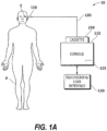
- a system 10 for treating an eye E of a patient P generally includes an eye treatment probe handpiece 110 coupled with a console 115 by a cassette 250.
- Handpiece 110 generally includes a handle for manually manipulating and supporting an insertable probe tip.
- the probe tip has a distal end which is insertable into the eye, with one or more lumens in the probe tip allowing irrigation fluid to flow from console 115 and/or cassette 250 into the eye.
- Aspiration fluid may also be withdrawn through a lumen of the probe tip, with console 115 and cassette 250 generally including a vacuum aspiration source, a positive displacement aspiration pump, or both to help withdraw and control a flow of surgical fluids into and out of eye E.
- cassette 250 will often comprise a sterilizable (or alternatively, disposable) structure, with the surgical fluids being transmitted through flexible and/or rigid conduits 120 of cassette 250 that avoid direct contact in between those fluids and the components of console 115.
- an electrical conductor and/or pneumatic line may supply energy from console 115 to an ultrasound transmitter of handpiece 110, a cutter mechanism, or the like.
- handpiece 110 may be configured as an irrigation/aspiration (I/A) and/or vitrectomy handpiece.
- the ultrasonic transmitter may be replaced by other means for emulsifying a lens, such as a high energy laser beam.
- the ultrasound energy from handpiece 110 helps to fragment the tissue of the lens, which can then be drawn into a port of the tip by aspiration flow. So as to balance the volume of material removed by the aspiration flow, an irrigation flow through handpiece 110 (or a separate probe structure) may also be provided, with both the aspiration and irrigation flows being controlled by console 115.
- cassette 250 and its flexible conduits 120 may be disposable.
- the flexible conduit or tubing may be disposable, with the cassette body and/or other structures of the cassette being sterilizable.
- Cassette 250 may be configured to interface with reusable components of console 115, including, but not limited to, peristaltic pump rollers, a Venturi or other vacuum source, a controller 125, and/or the like.
- Console 115 may include controller 125, which may include an embedded microcontroller and/or many of the components common to a personal computer, such as a processor, data bus, a memory, input and/or output devices (including a user interface 130 (e.g. touch screen, graphical user interface (GUI), etc.), and the like. Controller 125 will often include both hardware and software, with the software typically comprising machine readable code or programming instructions for implementing one, some, or all of the methods described herein.
- the code may be embodied by a tangible media such as a memory, a magnetic recording media, an optical recording media, or the like.
- Controller 125 may have (or be coupled with) a recording media reader, or the code may be transmitted to controller 125 by a network connection such as an internet, an intranet, an ethernet, a wireless network, or the like.
- controller 125 may include stored data for implementing the methods described herein; and may generate and/or store data that records parameters corresponding to the treatment of one or more patients.
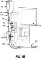
- an irrigation source 151 may be configured as a bottle or bag hanging from an IV pole hanger 150. It is understood by those skilled in the art that, while an integrated IV pole is illustrated, other configurations, utilizing standalone/static IV poles, pressurized infusion sources, and/or other suitable configurations, are contemplated by the present disclosure.
- An exemplary irrigation path for fluid may be realized via tubing cassette 154 having cassette tubing interface 153, which receives fluid from irrigation source 151 via drip chamber 152.
- Irrigation line 156A and aspiration line 157 are coupled to handpiece 158.
- Irrigation fluid may flow from drip chamber 152 through the irrigation tubing into tubing cassette 154.
- Irrigation fluid may then flow from the tubing cassette through handpiece irrigation line 156A which may be coupled to an irrigation port on handpiece 158.
- Aspirated fluid may flow from the eye through the handpiece aspiration line 157 back to tubing cassette 154 and into a waste collection bag 155.
- a touch screen display 159 may be provided to display system operation conditions and parameters, and may include a user interface (e.g., touch screen, keyboard, track ball, mouse, etc. - see controller 125 of FIG. 1A ) for entering data and/or instructions to the system of FIG. 1B .
- a user interface e.g., touch screen, keyboard, track ball, mouse, etc. - see controller 125 of FIG. 1A
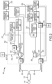
- Handpiece 110 may be connected to (or coupled with) the input side of sensor 221, typically by fluid pathways such as fluid pathway 220.
- Sensor 221 may be a pressure, flow, or a vacuum sensor that measures pressure, flow or vacuum, respectively. In a preferred embodiment, sensor 221 is a pressure sensor.
- the output side of sensor 221 is connected to valve 202 and also connected to pump 205 within cassette 250 via fluid pathway 222.
- Valve 202 maybe any known valve in the art, e.g. flow selector valve, rotary valve, etc. Valve 202 may also be coupled with pump 205.
- the exemplary embodiment may configure valve 202 to interface between handpiece 110, vacuum tank 204, pump 205, which may be a peristaltic pump but may be another type of pump, and collection 206.
- the system may operate valve 202 to connect handpiece 110 with vacuum tank 204 or with pump 205 based on signals received from console 115 resulting from the surgeon's input to user interface 130 or touch screen display 159.
- Handpiece 110 is connected to pump 205 and valve 202 provides fluidic connection and disconnection between handpiece 110 and tank 204.
- an aspiration level sensor 210 may be communicatively coupled to vacuum tank 204.
- the valve 202 illustrated in FIG. 2 may provide a connection between vacuum tank 204 and fluid pathway 222.
- the exemplary embodiment is not limited to one valve and may be realized using two valves each having at least two output ports, possibly connected together to provide the functionality described herein.
- a pair of two valves may be configured in a daisy chain arrangement, where the output port of a first valve is directly connected to the input port of a second valve.
- Console 115 may operate both valves together to provide three different flow configurations. For example, using two valves, valve one and valve two, valve one may use output port one, which is the supply for valve two. Valve two may connect to one of two ports providing two separate paths.
- valve 202 may be or comprise one or more pinch valves.
- the one or more pinch valves may be located along fluid pathway 220, 222 and/or 223, or any other fluid pathway as discussed herein.
- Console 115 may also comprise vacuum pressure center 260 which may provide a vacuum through fluid pathway 224 to vacuum tank 204.
- the vacuum provided through fluid pathway 224 may be regulated by control module 261 based on signals received from aspiration control module 263 which may result from the surgeon's input to user interface 130 and/or based on other signals received from sensor 221.
- Aspiration control module 263 may also control pump control 264 and allow for operation of pump 205 for the movement of fluid from both the handpiece 110 and the vacuum tank 204 to collector 206 via pathway 225.
- vacuum pressure center 260 includes a vacuum source 262, such as a venturi pump and an optional control module 261 (and valve (not shown)), but other configurations are possible.
- vacuum pressure center 260 may operate to remove air from the top of vacuum tank 204 and deliver the air to atmosphere (not shown). Removal of air from vacuum tank 204 in this manner may reduce the pressure within the tank, which may reduce the pressure in the attached fluid pathway 220, to a level less than the pressure within eye 114.
- a lower reservoir pressure connected through valve 202 may cause fluid to move from the eye, thereby providing aspiration.
- valve 202 is illustrated in FIG. 2 associated with aspiration, it is to be understood that this illustration represents a valve arrangement, including one or more valves (e.g. flow selector valve, rotary valve, or the like) performing the functionality described herein, and is not limited to a single device or a single valve.
- a strain gauge or other suitable component may communicate or signal information to console 115 to provide an amount of vacuum sensed in the handpiece fluid pathway 220.
- Console 115 may determine the actual amount of vacuum present based on the communicated information.
- sensor 221 monitors fluid pressure in the line, and can be used to determine when fluid flow should be reversed, such as encountering a certain pressure level (e.g. in the presence of an occlusion), and based on values obtained from the sensor 221, the system may control valve 202 and the pumps illustrated. It is to be understood that while components presented in FIG. 2 and other drawings of the present application are not shown connected to other system components, such as console 115, they are in fact connected for the purpose of monitoring and control of the components illustrated.
- the exemplary embodiment employs sensor 221 to monitor the flow conditions and provide signals representing flow conditions to the system such as via console 115 for the purpose of controlling components shown including but not limited to valve 202 and the pumps shown.
- the fluid pathways or flow segments of surgical cassette system 200 may include the fluid connections, for example flexible tubing, between each component represented with solid lines in FIG. 2 .
- the fluid connections may include molded fluid channels.
- Handpiece 110 may be connected to (or coupled with) the output side of irrigation pressure sensor 231, typically by fluid pathways such as fluid pathway 230.
- Sensor 231 may be a pressure, flow, or a vacuum sensor that measures pressure, flow or vacuum, respectively.
- sensor 231 is a pressure sensor.
- the input side of irrigation pressure sensor 231 is connected to valve 203 within cassette 250 via fluid pathway 232.
- Valve 203 may be any known valve in the art, e.g. flow selector valve, rotary valve, etc.
- the exemplary embodiment may configure valve 203 to interface between handpiece 110, irrigation tank 242, pump 240, which may be a peristaltic pump but may be another type of pump, and irrigation fluid source 112. In this configuration, the system may operate valve 203 to connect handpiece 110 with gravity feed or pressurized irrigation based on signals received from console 115 resulting from the surgeon's input to user interface 130.
- the valve 203 illustrated in FIG. 2 may provide a connection between irrigation tank 242, irrigation fluid source 112, and fluid pathway 232.
- the exemplary embodiment is not limited to one valve and may be realized using two valves each having at least two output ports, possibly connected together to provide the functionality described herein.
- a pair of two valves may be configured in a daisy chain arrangement, where the output port of a first valve is directly connected to the input port of a second valve.
- Console 115 may operate both valves together to provide three different flow configurations. For example, using two valves, valve one and valve two, valve one may use output port one, which is the supply for valve two. Valve two may connect to one of two ports providing two separate paths.
- valve 203 may be or comprise one or more pinch valves.
- the one or more pinch valves may be located along fluid pathway 230, 232, 233, 234 and/or 235, or any other fluid pathway as discussed herein.
- Console 115 may also comprise irrigation pressure center 270 which may provide a positive pressure through fluid pathway 237 to irrigation tank 242 using an applied pressure from pressure source 272.
- the pressure provided through fluid pathway 237 may be regulated by control module 271 based on signals received from irrigation control module 273 which may result from the surgeon's input to user interface 130 and/or based on other signals received from sensor 231.
- Irrigation control module 273 may also control pump control 274 and allow for operation of pump 240 for the movement of fluid from irrigation fluid source 112 to collector irrigation tank 242 via pathway 236.
- an irrigation level sensor 211 may be communicatively coupled to irrigation tank 242.
- FIG. 2 While a single valve 203 is illustrated in FIG. 2 associated with irrigation, it is to be understood that this illustration represents a valve arrangement, including one or more valves performing the functionality described herein, and is not limited to a single device or a single valve.
- a strain gauge or other suitable component may communicate or signal information to console 115 to provide an amount of pressure sensed in the handpiece fluid pathway 230.
- an amount of vacuum or flow may be sensed in the handpiece fluid pathway 230 and communicated to console 115.
- Console 115 may determine the actual amount of pressure present based on the communicated information.
- FIG. 3 illustrates an exemplary cassette system showing some of the features which may be employed in a phaco system.
- the illustrated cassette body 300 of cassette 250 is shown from the back side (or second side).
- Cassette body (or cassette fluidics portion) 300 may include a series of detents, also referred to as notches or catch surfaces, along its outer edge for receiving at least a portion of a retention device which may be associated with a surgical console to facilitate the retaining of the cassette to console and to at least partially assist in properly seating the cassette in the portion of the console meant to receive the cassette.
- a series of detents also referred to as notches or catch surfaces
- a cassette may include at least three sets of detents capable of accepting an attachment means provide by the console, such as, for example, upper detents 310, center detents 311, and lower detents 312. As will be described in greater detail below, the detents may be operated on in tandem or in a piecemeal fashion by a retention device of the surgical console.
- An exemplary cassette may also include at least one pressurized fluid inlet 321 which may be in fluid communication with at least one filter within filter cavity 320.
- the pressurized fluid for example, air
- the pressurized fluid may be supplied to the cassette through fluid inlet 321 and introduced into pressurized irrigation tank 340 and may be in further communication with pressure sensor 360.
- the vacuum applied through vacuum inlet 323 may be in communication with vacuum tank 342 and may be in further communication with aspiration channel 330 and aspiration channel 370.
- Each of the pressurized irrigation tank 340 and vacuum tank 342 may include a level sensing device 344 and 346, respectively.
- Irrigation fluid may enter the cassette through inlet 382 and may enter irrigation channel 332.
- Irrigation valve 350 controls the flow of irrigation fluid and may allow for gravity fed irrigation fluid to be supplied to irrigation outlet 380 from irrigation channel 332 or pressurized irrigation fluid from pressurized irrigation tank 340. In either instance, and even when irrigation valve 350 is in the "off" position relative to both irrigation fluid sources, the amount of pressure associated with the delivery of the irrigation fluid may be measured by irrigation sensor 360. Similarly, aspiration pressure may be measured by the aspiration sensor 362 in close proximity to aspiration inlet 384. Aspiration fluid which may enter though aspiration inlet 384 may enter aspiration channel 330 under pressure produced by at least one peristaltic pump, for example, and may also enter vacuum tank 342 under the influence of at least a partial vacuum through valve 352.
- cassette 250 may also include at least two rotary valves which may enable the cassette to change modes for aspiration and irrigation.
- the aspiration valve switches between flow mode aspiration and vacuum mode aspiration, with an off position between the two mode positions.
- the irrigation valve switches between gravity mode irrigation and pressurized irrigation, with an off position in between the two modes.
- gravity irrigation mode the bottle height may control the irrigation pressure.
- the irrigation valve may be turned such that the flow from the bottle flows through the irrigation valve to the pressure sensor and out to the surgical site through the handpiece.
- the fluidic channel to the irrigation pump may be sealed off by means of the pump rollers sealing off the peristaltic pump bladder. If the irrigation pump is not running, there will be no flow through the pump.
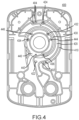
- the system may include a cassette having an internal flow interface as at least partially illustrated in FIG. 4.
- FIG. 4 illustrates the back side (or second side) of a cassette 250.
- Such a cassette flow interface may receive fluids, as described in greater detail herein, which may be driven by bladders joined to cassette 250 to move fluids through the cassette.
- Cassette fluidics portion (or cassette body) 400 may include a plurality of channels, each with at least one inlet and one outlet. Each channel formed in the cassette fluidics portion 400.
- channel 410 may have outlet 402 and outlet 404.
- Each of outlet 402 and 404 may include a plurality of openings in which fluids may enter and exit the channel 410.
- channel 420 may have at least one inlet 424 and inlet 422.
- fluids When used for transmitting aspiration liquids during cassette engagement, fluids may travel through channel 410, pass through outlets 402 and 404 and then enter drain channel 420 through inlet 424 and inlet 422.
- the outlets from channel 410 may be in fluid communication with specific inlets in channel 420.
- Each inlet and outlet described herein may be shaped to control flow and turbulence of the fluid to be moved through the cassette and may be circular, oval, and/or any shape which may impact fluid flow. As would be appreciated by those skilled in the art, the flow may be reversed and may be used for both irrigation and aspiration functions as desired by the user.
- the cassette fluidics portion 400 may include channels that allow for simultaneous flow through a variety of inlets and outlets within the same channel network to provide desired flow characteristics, such as control of flow and turbulence.
- irrigation fluid may enter the cassette 250 through channel 440 with fluid exiting through outlets 442, 446, and 444.
- the fluid may enter channel 430 through inlets 434, 432, and 436.
- the outlets from channel 440 may be in fluid communication with specific inlets in channel 430.
- Each inlet and outlet described herein may be shaped to control flow and turbulence of the fluid to be moved through the cassette and may be circular, oval, and/or any shape which may impact fluid flow.
- the flow may be reversed and may be used for both irrigation and aspiration functions as desired by the user.
- channel 410 may have an inlet from an aspiration tube connection to a cassette, such as connection 384 and pressure sensor area 362 of FIG. 3 .
- the ports 402 and 404 of FIG. 4 may be channel 410 outlets.
- channel 410 outlets may also be bladder inlets (i.e., inlet is larger, bypass is smaller).
- Ports 402 may be inlet ports to aspiration bladder section 506.
- port 404 may be a bypass port to 505.
- Port 424 may be a bladder outlet port from 506 and port 422 may be the outlet for 505.
- channel 420 may be an aspiration drain channel with the drain connected to a drain hole 370.
- the aspiration bladder rollers may be configured to rotate counter-clockwise.
- An irrigation pump which may have clockwise rotating rollers in FIG. 4 , may supply fluid from 382 into channel 332.
- Ports 442 of bladder section 512, port 446 of bladder section 511, and port 444 of bladder section 510 may be irrigation bladder inlet ports.
- the irrigation outlet ports may include: port 434 (bladder section 512), port 432 (bladder section 511) and port 436 (bladder section 510), and direct flow from the bladder to the irrigation tank 340, through channel 430.
- the cassette 250 may include an assembly of bladders including at least one aspiration bladder.
- aspiration bladder may include two sections, such as section 505 and section 506.
- the assembly of bladders may include an irrigation bladder.
- the irrigation bladder may include three sections, such as section 510, section 511, and section 512.
- An assembly of compressible bladders as illustrated in FIG. 5A on assembly 515 may be communicatively coupled to the back of cassette fluidics portion 400 and may form a part of cassette 250 and may comprise a plurality of bladders which may form at least the top portion of a fluid channel which may interoperate with the fluid channels illustrated in cassette fluidics portion 400.
- bladder 505 may communicatively connect outlet 404 and inlet 422.
- bladder 506 may communicatively connect outlet 402 and inlet 424.
- Bladder 510 may communicatively connect outlet 444 and inlet 436
- bladder 511 may communicatively connect outlet 446 and inlet 432
- bladder 512 may communicatively connect outlet 442 and inlet 434.
- each of the bladders of assembly 515 may form a channel when placed against a planar surface, which channels may be linearly uniform and/or have a variable volume over their respective lengths.
- an aspiration bladder may be mounted to a flat surface and an irrigation bladder may be mounted to and make a channel with a conical surface.
- each bladder may have at least a minimum uniform channel volume throughout the channel as measured by a measured height formed between the bladder 560 and a planar surface represented by line 550.
- the minimum uniform height may be greater than about 0.5 mm and may be less than about 3.5mm (although each channel may be nonuniform in height and/or radius and may be designed to hold a specific volume of fluid).
- the minimum uniform radius of a channel may be greater than about 1.5 mm and may be less than about 3.5 mm.
- the minimum radius at position 522 may be 2.25mm. At least one second radius may be found within the bladder, such as a height of 3.5mm at position 524.
- the at least one second length portion 530 may be bordered on each side by first length portion 520 and third length portion 525.
- the change in height between first length portion 520 and second length portion 530 may occur gradually over the length of first length portion 520, for example, or may occur over a small distance between the two portions sufficient to accommodate an angular rise.
- an angular rise may be equivalent to about 118 degrees from the top-most portion of first height portion.
- bladder 560 may have at least two foot portions 540 located in either end of the bladder which may be at least partially in communication with planar surface 550.
- the top of bladder 560 may not follow the same geometry as the inner channel forming portion and may include additional angular elements.
- first portion 520 may include a sloped portion on its proximate end while second portion 530 may include at least two sloped portions to accommodate any underlying channel height rise as between first portion 520 and third portion 525.
- the thickness of the bladder may be substantially uniform over most of its length and may be generally concave over the channel forming portion of the bladder.
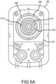
- cassette 250 may comprise cassette body 300 which may include on the front face assembly 515 and panel 560.
- Valves 352 and 350 may be at least partially housed within cassette body 300 and in an embodiment, may be at least partially retained in cassette body 300 by panel 560.
- pressure sensors 360 and 362 may be placed in communication with cassette body 300 and in an embodiment, may be sealed and/or retained by panel 560.
- assembly 515 and panel 560 may be combined into a single article and may be mechanically and/or chemically fastened to cassette body 300.
- Tubing assembly 585 may include fluid pathways for both irrigation and aspiration, for example, to fluidly couple with a surgical handpiece.
- Tubing assembly 585 may be preferably connected to the bottom of cassette body 300 for ease of use but may be joined at any position to cassette body 300 as may be considered useful by those skilled in the art.
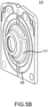
- the back side of cassette body 300 may include filters 565 and may be sealed by plate 570.
- plate 570 may be mechanically and/or chemically fastened to cassette body 300, for example.
- Drain bag 580 may be fastened to the exterior of plate 570 and may be in fluid communication with one or more fluid conduits within cassette body 300. Fluid from within the cassette body 300 may be expelled into fluid bag 580, which may be replaceable and/or itself drained to allow for the expelling of more fluid than could be held in the volume of a single fluid bag 580.
- Panel 570 may also have attached thereto handle 575 which may provide for easier handling of cassette 250, for example during insertion and removal from a surgical console. Handle 575 may be attached at one or more points on panel 570 and may take any number of forms, such as, for example, a ring, square, or other geometric shape.
- the bladder assembly may have portions offset from one another and may have portions in multiple planes, for example.
- One or more of the bladders may include conic portions, cylindrical portions, and wavy portions, for example.
- a first bladder assembly may be in a first plane and a second bladder assembly may be in a second plane.
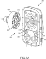
- the console engagement side of cassette 250 may include assembly 515 which may be shaped to compliantly accept a roller head assembly 600 (which is shown in repose from a surgical console).
- the roller head assembly 600 may comprise at least two pump heads, each of which may operate independently from each other.
- the outermost pump head, pump head 605, for example, may comprise a vertically disposed surface (relative to cassette 250) which may include a plurality of roller assemblies, such as roller assembly 620.
- An inner pump head, pump head 610 may have a non-linear shape and may, for example, be shaped as a conical frustum, for example.
- Each pump head may also be spring loaded and or otherwise moveable such that each pump head may have the ability to adjust to the orientation of a mating cassette.
- Each roller assembly may contain rollers having geometry to minimize slip between a portion of the roller assembly surface and a bladder.
- a roller may have a conical geometry which allows the roller axis to pass approximately through the center of roller rotation.
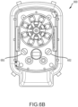
- FIG. 6B shows an illustration of the console interface or cassette receptacle for mating a single use cassette with the console.
- the irrigation and aspiration valves on the single use cassette will center on each of irrigation valve lever 650 and aspiration lever valve 652, respectively, once the cassette has been mounted to the console interface 800.
- each one of the valve levers may operate responsive to at least one received signal indicative of at least one parameter.
- Such parameters may include, for example, fluid pressure and fluid volume associated with fluid in the system, whether or not the fluid is in communication with either valve.
- a parameter associated with at least one of a vacuum, a positive pressure and gravity may also be used.
- Each of the irrigation valve and aspiration valve may be in fluid communication with each other.
- the valves may also be fluidly connected to a line under vacuum and/or to atmosphere.
- the valves may receive one of either pressurized fluid or gravity-fed fluid and may provide a vent for at least one fluidly connected line. Either one of the valves may be partially open to at least one line communicatively connected thereto.
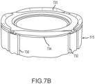
- roller assemblies of the pump heads may communicatively engage the bladders of assembly 515.
- pump head 605 may comprise a roller assembly which may further comprise a roller 712, roller body 711 and a spring means 710.
- Roller 712 may be movably affixed to roller body 711 and may be under a downward force provided by spring means 710, which itself may be affixed to both the pump head 605 and roller body 711.
- Each roller 712 may engage a portion of a bladder 720 which may be removably affixed to a portion of assembly 515 and may engage a bladder with sufficient force as to deform the bladder and cause fluid flow within the channel formed between the bladder 720 and the assembly 515.
- a roller may deform the bladder is a manner sufficient to stop all fluid flow
- a portion of assembly 515 may include ports, such as ports 730 and 732, which may correspond to inlets and outlets of fluid channels located on the opposite side of assembly 515 as discussed above. Shown without the pump head, the portion of assembly 515 may comprise multiple bladders, each creating a flow channel 734 between the bladder and assembly 515. Although the illustration shows two ports into channel 734, any number of ports may be provided.
- a control module associated with a surgical console may control at least one motor which may control the at least two pump heads.
- each individual pump head may be independently rotated and controlled from a dedicated motor and/or a single motor and may further be responsive to at least one spring mechanism to allow for adjustments in orientation of the pump heads relative to an engaged cassette.
- Each pump head may be controlled by a dedicated motor placed in line along a shaft which may itself have at least two independent drive shafts.
- the pump heads may provide peristaltic flow within the engaged cassette and provide rotation in either a forward or reverse direction.
- the control module may receive signals from the pump motor(s) and associated pump encoder(s) responsive to signals received from the surgical console and/or attached devices, such as, for example, a foot pedal and a surgical instrument.
- the encoder may comprise an index line output on the motor shaft. There may be two hard stops within the cassette at the following positions: for irrigation at: pressurized irrigation connected and gravity irrigation connected; and for aspiration at: vacuum tank connected and vacuum tank disconnected. There may be a third position on the irrigation valve of irrigation off (no irrigation flow out of the cassette). It is possible to use the index line of the encoder or an absolute position encoder to know the physical orientation of the valve driver head. This may require alignment of the index position to the pump driver head position during manufacturing. A spring in the valve driver head may be used to mate with the rotary valve in the cassette without knowing the orientation of the valve driver head. This would rely on the spring loading to be reliable over wear and would allow the heads to be resistant to any misalignment with a part of the pump head and the cassette.
- the motor may spin until the index line is activated, which may be used to place the valve driver head in a specific orientation and zero the encoder counts and motor driver step position.
- the valve stepper motor may spin so that the spring-loaded valve driver head may mate with the cassette.
- the motor may continue spinning until it hits a hard stop in the cassette. There may be a timeout or certain number of rotations to allow before setting an error that the valve head has not mated.
- the motor position at the hard stop (reported from either/both the motor driver step position and/or the encoder position) may be saved for returning to that position later during operation.
- the motor may rotate in the opposite direction to hit the second hard stop.
- the encoder and/or step position may be saved for returning to that position later during operation.
- the angular travel range between hard stops can be checked for an error condition (if there is foreign material or stiction stalling the motor before a hard stop), and the middle irrigation position of off can be set as the middle of the irrigation hard stop range.
- Safe state for the system may be when gravity irrigation is connected and aspiration is stopped.
- the irrigation valve may need to return to the gravity position in a safe state error condition.
- the system may require either having the system battery backup always being present and sufficient for the 10 seconds of operation or providing enough capacitive hold on the 24V line and an indication that power is going down to move the valve to the intended position if the battery backup is insufficient.
- a peristaltic pump consists of elements that pinch and articulate along the closed flexible fluid conduit created, in part, by an aspiration bladder, to force fluid through the conduit.
- At least two pinchers particularly pump head rollers, or alternatively wipers, cams, or shoes, sequentially engage and pinch the conduit against a rigid structure and articulate along the conduit length to cause fluid flow.
- a subsequent pincher engaged the conduit and articulated along it to ensure continued fluid flow.
- a momentary disruption of downstream flow may occur as fluid fills the void as the conduit regains its pre-deformed shape.
- upstream flow may be disrupted as the subsequent pincher engages the conduit and fluid is displaced.
- one typical method to mitigate such pulsation may involve shaping a rigid structure to control the manner in which the pinchers engage and disengage the conduit to lessen the severity of pulsation by increasing pulse duration.
- larger sections of bladder tubing may be used, as well as varying pump speed to cancel out known pulsations.
- Pulsation may also be diminished by employing a void in a rigid structure portion such that as three pinchers are simultaneously engaging the flexible conduit, the middle pincher momentarily encounters the rigid structure void thus reducing or eliminating its pinch before fully re-engaging the conduit.
- the manner in which the pincher encounters the void may mitigate pulsation upstream or downstream of the pump.
- other methods may employ a length of semicircular flexible open conduit with capped ends mounted and sealed to a rigid structure, with inlet and outlet flow are provided by ports in the rigid structure under the flexible conduit.
- the ends of the fluid volume of these conduits may be tapered to control the manner in which the pinchers engage and disengage the conduit.
- grooves in the rigid structure near the ends of the conduit may provide fluid bypass under the pinched conduit which lessens the severity of and increases the duration of pulses.
- a pulseless peristaltic pump may eliminate pulses upstream (inlet side) by providing a flexible conduit of varying volume or displacement in the section of conduit that is engaged by the pinchers.
- the pulse caused by the subsequent roller engaging the flexible conduit may be absorbed inside of this length of flexible conduit which may result in pulseless flow into the pump.
- the pulse is essentially cancelled at its source.
- roller tracks may be employed to promote constant pump speed and pulseless flow and decreases the cost and complexity of the pump motivating drive.
- At least two separate flexible conduits are arranged in a circular pattern, plumbed together in parallel, and engaged by a pump roller head, as illustrated by FIG. 6 .
- Each conduit may consist of a short length of semicircular or similarly shaped flexible open conduit (such as a bladder) that may be mounted and sealed to a cassette so that the cassette and bladder together form a fluid flow path, such as flow channel 734 as illustrated in FIG. 7B .
- Inlet and outlet flows are provided by ports in the cassette under each end of the bladders.
- the bladder sections may be plumbed in parallel inside the cassette while a motor-driven rotating pump head with eight pump roller heads, for example, engages the cassette and bladders.
- the rollers may be arranged in a circular pattern with the rotational axis of each roller intersecting the pump head rotational axis.
- the rollers may rotate along a flat and annular path on the front face of the cassette while simultaneously manipulating the bladders.
- upstream or inlet pulseless flow may be achieved by shaping the bladder so that the fluid volume of the conduit behind the first roller increases incrementally and exactly to absorb the fluid displaced as the second roller proceeds to pinch the bladders, as illustrated in FIG. 7A , for example.
- the pulse caused by the second roller may be absorbed inside of the bladder and may result in pulseless flow into the pump, which is embodied by a bulge in the bladder.
- Bypass ports in the cassette may be placed slightly downstream of the location where the rollers initially seal a bladder against the cassette. These ports may promote pulseless performance by precisely defining pumping handoff from the first roller to the second. Pump speed may be held constant through each pump rotation pump to avoid flow and pressure variation. Two features of the pump promote constant speed by reducing torque pulses caused by interaction between rollers and cassette. Rollers are primarily supported by the front face of the cassette. This mitigates torque variation by providing a smooth, flat, and rigid roller track surface. The bladder wall thickness is tapered at each end of the bladders which effectively provide ramps instead of bumps where the rollers engage and disengage the bladders, as illustrated in FIG. 5C , for example.
- a conical flexible open conduit with at least one fluid path of semi-circular or similar cross-section mounted and sealed to the inside or outside of a conical structure and manipulated by rollers in a rotary pump head may be used.
- a linear flexible open conduit with at least one fluid path of semi-circular or similar cross-section mounted and sealed to a flat or curved structure and manipulated by a linear pump head such as rollers that are linked together in a chain driven by pulleys or sprockets.
- a flexible conduit such as a round tube pinched against a flat or curved structure and manipulated by a linear pump head such as rollers that are linked together in a chain driven by pulleys or sprockets.
Landscapes
- Health & Medical Sciences (AREA)
- Heart & Thoracic Surgery (AREA)
- Public Health (AREA)
- Veterinary Medicine (AREA)
- Engineering & Computer Science (AREA)
- Biomedical Technology (AREA)
- General Health & Medical Sciences (AREA)
- Life Sciences & Earth Sciences (AREA)
- Animal Behavior & Ethology (AREA)
- Hematology (AREA)
- Anesthesiology (AREA)
- Vascular Medicine (AREA)
- Pulmonology (AREA)
- Ophthalmology & Optometry (AREA)
- Nuclear Medicine, Radiotherapy & Molecular Imaging (AREA)
- Surgery (AREA)
- Physics & Mathematics (AREA)
- Fluid Mechanics (AREA)
- External Artificial Organs (AREA)
- Saccharide Compounds (AREA)
Claims (10)
- System zum Verteilen von Flüssigkeit in einer chirurgischen Kassette (250), umfassend:eine teilweise verformbare Blase (560), die teilweise auf einer starren Oberfläche (550) angeordnet ist, wobei die Blase (560) einen Kanal (410) ausbildet;einen ersten Anschluss (402) und einen zweiten Anschluss (404) in Flüssigkeitsverbindung mit dem Kanal (410);wobei mindestens zwei Pumpenkopfrollen (620) mit der mindestens teilweise verformbaren Blase (560) in Eingriff stehen, wobei eine erste der mindestens zwei Pumpenkopfrollen (620) in einer ersten Richtung stromaufwärts der zweiten der mindestens zwei Pumpenkopfrollen (620) liegt,dadurch gekennzeichnet, dassder Kanal entlang der ersten Richtung einen ersten Abschnitt (520) und einen zweiten Abschnitt (525) umfasst, die eine im Wesentlichen gleichmäßige erste Abmessung aufweisen, die durch einen dritten Abschnitt (530) getrennt ist, der eine zweite Abmessung aufweist, die größer als die erste Abmessung ist, derart, dass ein Flüssigkeitsvolumen des Kanals (410) stromabwärts der ersten Pumpenkopfrolle (620) schrittweise zunimmt, um Flüssigkeit aufzunehmen, die durch die zweite Pumpenkopfrolle (620) stromaufwärts verdrängt wird.
- Kassette nach Anspruch 1, wobei eine der mindestens zwei Pumpenkopfrollen (620) einen Flüssigkeitsfluss durch den ersten Anschluss (410) im Wesentlichen stoppt.
- Kassette nach Anspruch 1, wobei eine der mindestens zwei Pumpenkopfrollen (620) den Flüssigkeitsfluss durch den zweiten Anschluss (420) im Wesentlichen stoppt.
- Kassette nach Anspruch 1, wobei die Blase (560) eine Abschrägung umfasst, die sich in der Nähe jedes Endes der Blase (560) befindet.
- Kassette nach Anspruch 1, wobei die mindestens eine starre Oberfläche (550) mindestens teilweise nicht linear ist.
- Kassette nach Anspruch 1, wobei mindestens ein Abschnitt der Blase (560) unterhalb der starren Oberfläche ist.
- Kassette nach Anspruch 1, wobei die Blase (560) aus Gummi oder Silikon besteht.
- Kassette nach Anspruch 1, wobei der Kanal (410) eine minimale Höhe von etwa 0,5 mm aufweist.
- Kassette nach Anspruch 1, wobei der Kanal (410) eine minimale Höhe von etwa 0,75 mm aufweist.
- Kassette nach Anspruch 1, wobei der Kanal (410) eine maximale Höhe von etwa 3,0 mm aufweist.
Applications Claiming Priority (2)
| Application Number | Priority Date | Filing Date | Title |
|---|---|---|---|
| US201962949435P | 2019-12-17 | 2019-12-17 | |
| PCT/IB2020/061904 WO2021124078A1 (en) | 2019-12-17 | 2020-12-14 | Systems and methods for providing a pulseless peristaltic pump |
Publications (2)
| Publication Number | Publication Date |
|---|---|
| EP4076565A1 EP4076565A1 (de) | 2022-10-26 |
| EP4076565B1 true EP4076565B1 (de) | 2025-03-12 |
Family
ID=73856211
Family Applications (1)
| Application Number | Title | Priority Date | Filing Date |
|---|---|---|---|
| EP20828319.2A Active EP4076565B1 (de) | 2019-12-17 | 2020-12-14 | Systeme und verfahren zur herstellung einer peristaltischen pulslosen pumpe |
Country Status (5)
| Country | Link |
|---|---|
| US (1) | US12447257B2 (de) |
| EP (1) | EP4076565B1 (de) |
| AU (1) | AU2020410412A1 (de) |
| CA (1) | CA3164934A1 (de) |
| WO (1) | WO2021124078A1 (de) |
Families Citing this family (3)
| Publication number | Priority date | Publication date | Assignee | Title |
|---|---|---|---|---|
| US11934209B2 (en) * | 2020-09-14 | 2024-03-19 | Alcon Inc. | Methods and systems for providing control stability in a vacuum generation system using an override proportional-integral-derivative (PID) controller |
| AU2024295294A1 (en) * | 2023-07-19 | 2025-11-27 | Alcon Inc. | Ophthalmic surgical cassette |
| WO2025093947A1 (en) * | 2023-10-31 | 2025-05-08 | Alcon Inc. | Pressure sensors for ophthalmic surgical consoles and cassettes |
Family Cites Families (249)
| Publication number | Priority date | Publication date | Assignee | Title |
|---|---|---|---|---|
| US2899907A (en) * | 1959-08-18 | Roller pump | ||
| US1949574A (en) | 1931-06-06 | 1934-03-06 | Willam F Cremean | Irrigator |
| US1848024A (en) | 1931-11-23 | 1932-03-01 | Norris T Owen | Apparatus for use in blood transfusion, intravenous medication and the like |
| US2466618A (en) * | 1945-09-18 | 1949-04-05 | Stocks Ronald Kingsley | Pump suitable for moving sludges and the like |
| US2841091A (en) * | 1953-11-16 | 1958-07-01 | Schaurte Paul | Apparatus for conveying gases or liquids |
| US3005345A (en) | 1959-05-01 | 1961-10-24 | Maxime G Kaufman | Fluid level indicator |
| US3116697A (en) | 1962-08-23 | 1964-01-07 | Technicon Instr | Compressible tube type fluid pump |
| US3693613A (en) | 1970-12-09 | 1972-09-26 | Cavitron Corp | Surgical handpiece and flow control system for use therewith |
| US3723030A (en) | 1971-03-03 | 1973-03-27 | Buchler Instr Division | Peristaltic pump with stacked components |
| GB1399243A (en) | 1971-03-31 | 1975-06-25 | Allen West Holding Co Ltd | Fluid flow valve |
| US3927955A (en) | 1971-08-23 | 1975-12-23 | East West Medical Products Inc | Medical cassette pump |
| US3781142A (en) | 1972-01-14 | 1973-12-25 | Flow Technology Corp | Peristalic pump with adjustable tensioning means |
| GB1417146A (en) | 1972-08-09 | 1975-12-10 | Rank Organisation Ltd | Peristaltic pumps |
| US3816033A (en) | 1972-11-21 | 1974-06-11 | Greiner Scient Corp | Multi-channel pump |
| DK140318B (da) | 1973-05-29 | 1979-07-30 | Erik Bach Kyvsgaard | Slangepumpe. |
| ZA753026B (en) * | 1974-05-29 | 1976-04-28 | J Galea | Fluid pump |
| GB1578022A (en) | 1976-05-05 | 1980-10-29 | Iles F | Peristaltic pumps |
| US4205948A (en) * | 1977-02-10 | 1980-06-03 | Jones Allan R | Peristaltic pump |
| US4189286A (en) | 1977-03-15 | 1980-02-19 | Fibra-Sonics, Inc. | Peristaltic pump |
| US4193004A (en) | 1978-06-22 | 1980-03-11 | Cobe Laboratories, Inc. | Fluid level monitoring through fluid cell protrusion |
| US4201525A (en) | 1978-07-05 | 1980-05-06 | Baxter Travenol Laboratories, Inc. | Peristaltic pump |
| US4297089A (en) | 1978-12-26 | 1981-10-27 | Ford Motor Company | Arcuate tubular pump |
| US4369785A (en) | 1980-02-21 | 1983-01-25 | Contemporary Ocu-Flo, Inc. | Surgical fluid flow system |
| SE8100044L (sv) | 1981-01-07 | 1982-07-08 | Vitrum Ab | Pump |
| US4515584A (en) | 1982-07-06 | 1985-05-07 | Fujisawa Pharmaceutical Co., Ltd. | Artificial pancreas |
| JPS59154259U (ja) | 1983-04-01 | 1984-10-16 | 株式会社ウベ循研 | 血液用円錐形送液ポンプ |
| DE3326786A1 (de) | 1983-07-25 | 1985-02-14 | Fresenius AG, 6380 Bad Homburg | Pumpenbett fuer eine rollenpumpe |
| US4671116A (en) | 1984-11-30 | 1987-06-09 | Eaton Corporation | Fluid pressure transducer |
| US4644177A (en) | 1984-12-31 | 1987-02-17 | Technical Research Associates | Fluid level and condition detector system |
| US4657490A (en) | 1985-03-27 | 1987-04-14 | Quest Medical, Inc. | Infusion pump with disposable cassette |
| CA1280326C (en) | 1985-09-25 | 1991-02-19 | Leif Joakim Sundblom | Fast response tubeless vacuum aspiration collection cassette |
| US4909713A (en) | 1986-05-07 | 1990-03-20 | Cobe Laboratories, Inc. | Peristaltic pump |
| US4773897A (en) | 1986-11-06 | 1988-09-27 | Storz Instrument Company | Collection container for ophthalmic surgical system |
| US5195960A (en) | 1987-04-27 | 1993-03-23 | Site Microsurgical Systems, Inc. | Disposable vacuum/peristaltic pump cassette system |
| US5125891A (en) | 1987-04-27 | 1992-06-30 | Site Microsurgical Systems, Inc. | Disposable vacuum/peristaltic pump cassette system |
| US4842584A (en) | 1987-05-01 | 1989-06-27 | Abbott Laboratories | Disposable fluid infusion pumping chamber cassette and drive mechanism thereof |
| US5006110A (en) | 1987-12-01 | 1991-04-09 | Pacesetter Infusion, Ltd. | Air-in-line detector infusion system |
| WO1993012743A1 (fr) | 1988-04-20 | 1993-07-08 | Susumu Takahashi | Appareil d'aspiration |
| US4982903A (en) | 1988-06-17 | 1991-01-08 | Ransburg Corporation | Peristaltic voltage block |
| US4878622A (en) | 1988-06-17 | 1989-11-07 | Ransburg Corporation | Peristaltic voltage block |
| US4920336A (en) | 1988-11-22 | 1990-04-24 | Fisher Scientific Company | Method and apparatus for monitoring the level of the contents in a container |
| US5163900A (en) | 1989-03-16 | 1992-11-17 | Surgin Surgical Instrumentation, Inc. | Disposable cassette systems |
| GB2230301A (en) | 1989-04-07 | 1990-10-17 | Unilever Plc | Adjustable peristaltic pump |
| US4983901A (en) | 1989-04-21 | 1991-01-08 | Allergan, Inc. | Digital electronic foot control for medical apparatus and the like |
| US5084031A (en) | 1989-09-12 | 1992-01-28 | Research Medical, Inc. | Cardioplegia three-way double stopcock |
| US5062775A (en) | 1989-09-29 | 1991-11-05 | Rocky Mountain Research, Inc. | Roller pump in an extra corporeal support system |
| US4997347A (en) | 1990-01-12 | 1991-03-05 | Autotrol Corporation | Peristaltic motor |
| US5235179A (en) | 1991-09-24 | 1993-08-10 | Hughes Aircraft Company | Evanescent wave liquid level sensor with density compensation |
| US5267956A (en) | 1992-02-05 | 1993-12-07 | Alcon Surgical, Inc. | Surgical cassette |
| US5499969A (en) | 1992-02-05 | 1996-03-19 | Nestle S.A. | Microsurgical cassette |
| US5195971A (en) | 1992-02-10 | 1993-03-23 | Advanced Cardiovascular Systems, Inc. | Perfusion type dilatation catheter |
| WO1993017729A1 (en) | 1992-03-03 | 1993-09-16 | Alcon Surgical, Inc. | System and apparatus for controlling fluid flow from a surgical handpiece |
| US5230614A (en) | 1992-06-03 | 1993-07-27 | Allergan, Inc. | Reduced pulsation tapered ramp pump head |
| EP0643570B1 (de) | 1992-06-03 | 1998-08-12 | Allergan, Inc. | Schlauchleitungenanordnungssystem |
| US5342181A (en) | 1992-06-15 | 1994-08-30 | Datascope Investment Corp. | Single roller blood pump and pump/oxygenator system using same |
| US5268624A (en) | 1992-10-14 | 1993-12-07 | Allergan, Inc. | Foot pedal control with user-selectable operational ranges |
| US5354268A (en) | 1992-11-04 | 1994-10-11 | Medical Instrument Development Laboratories, Inc. | Methods and apparatus for control of vacuum and pressure for surgical procedures |
| ATE187652T1 (de) | 1992-11-06 | 2000-01-15 | Grieshaber & Co Ag | Ophthalmologisches aspirations- und irrigationssystem |
| EP0601313B1 (de) | 1992-11-06 | 1999-03-03 | GRIESHABER & CO. AG SCHAFFHAUSEN | Einrichtung für mikrochirurgische Eingriffe am Auge eines Lebewesens |
| US5340290A (en) * | 1992-12-21 | 1994-08-23 | Scilog, Inc. | Double feed peristaltic pump |
| US5342293A (en) | 1993-06-22 | 1994-08-30 | Allergan, Inc. | Variable vacuum/variable flow phacoemulsification method |
| DE4327152C2 (de) | 1993-08-12 | 1995-10-19 | Stoeckert Instr Gmbh | Rollenpumpe |
| US6138508A (en) | 1993-10-27 | 2000-10-31 | Kdi Precision Products, Inc. | Digital liquid level sensing apparatus |
| GB2285837B (en) * | 1994-01-24 | 1998-05-13 | Varian Australia | Peristaltic pump |
| US5591127A (en) | 1994-01-28 | 1997-01-07 | Barwick, Jr.; Billie J. | Phacoemulsification method and apparatus |
| US5792117A (en) | 1994-07-22 | 1998-08-11 | Raya Systems, Inc. | Apparatus for optically determining and electronically recording injection doses in syringes |
| DE9412228U1 (de) | 1994-07-28 | 1994-09-22 | Loctite Europa E.E.I.G. (E.W.I.V.), 85748 Garching | Schlauchpumpe zur genauen Dosierung kleiner Flüssigkeitsmengen |
| US5468129A (en) * | 1994-08-05 | 1995-11-21 | Cole Parmer Instrument Company | Peristaltic pump |
| EP0717970A1 (de) | 1994-12-20 | 1996-06-26 | GRIESHABER & CO. AG SCHAFFHAUSEN | Opthalmologische Aspirations- und Irrigationseinrichtung sowie Verfahren zum Betreiben derselben |
| US5540668A (en) | 1995-01-20 | 1996-07-30 | Wilson, Jr.; Roland B. | Anti-cross contamination valve and fluid delivery systems using same |
| US5591344A (en) | 1995-02-13 | 1997-01-07 | Aksys, Ltd. | Hot water disinfection of dialysis machines, including the extracorporeal circuit thereof |
| US5810766A (en) | 1995-02-28 | 1998-09-22 | Chiron Vision Corporation | Infusion/aspiration apparatus with removable cassette |
| US5569188A (en) | 1995-04-11 | 1996-10-29 | Mackool; Richard J. | Apparatus for controlling fluid flow through a surgical instrument and the temperature of an ultrasonic instrument |
| US5657000A (en) | 1995-06-02 | 1997-08-12 | Cobe Laboratories, Inc. | Peristaltic pump occlusion detector and adjuster |
| JPH0929989A (ja) | 1995-07-14 | 1997-02-04 | Canon Inc | インク有無検出装置、インクタンク、キット、記録ユニット、記録装置、および情報処理システム |
| US5549461A (en) | 1995-07-21 | 1996-08-27 | Newland; George | Peristaltic pump attachment for slurry mixers |
| FR2737261B1 (fr) | 1995-07-27 | 1997-10-10 | Jean Francois Ognier | Pompe peristaltique |
| CA2186805C (en) | 1995-12-01 | 2001-03-27 | Christopher C. Jung | Apparatus and method for sensing fluid level |
| US5899674A (en) | 1995-12-01 | 1999-05-04 | Alcon Laboratories, Inc. | Indentification system for a surgical cassette |
| US5830176A (en) | 1995-12-26 | 1998-11-03 | Mackool; Richard J. | Maintenance of pressure within a surgical site during a surgical procedure |
| US5676530A (en) | 1996-01-24 | 1997-10-14 | Alcon Laboratories, Inc. | Surgical cassette latching mechanism |
| US5840069A (en) * | 1996-04-04 | 1998-11-24 | Medtronic, Inc. | Implantable peristaltic pump techniques |
| DE69731472T2 (de) | 1996-08-15 | 2005-10-20 | Deka Products Ltd. Partnership | Pumpe und system zur medizinischen irrigation |
| DE69728793T2 (de) | 1996-08-29 | 2004-09-23 | Bausch & Lomb Surgical, Inc. | Frequenz- und leistungsregelunganordnung mit doppelkreis |
| US6117126A (en) | 1996-08-29 | 2000-09-12 | Bausch & Lomb Surgical, Inc. | Surgical module with independent microprocessor-based communication |
| US6086598A (en) | 1996-08-29 | 2000-07-11 | Bausch & Lomb Surgical, Inc. | Ophthalmic microsurgical system having color sensor for cassette identification |
| US5941696A (en) * | 1996-09-10 | 1999-08-24 | Embrex, Inc. | Peristaltic pump |
| US5792167A (en) | 1996-09-13 | 1998-08-11 | Stryker Corporation | Surgical irrigation pump and tool system |
| US5733256A (en) | 1996-09-26 | 1998-03-31 | Micro Medical Devices | Integrated phacoemulsification system |
| US5746719A (en) | 1996-10-25 | 1998-05-05 | Arthur D. Little, Inc. | Fluid flow control system incorporating a disposable pump cartridge |
| US7169123B2 (en) | 1997-01-22 | 2007-01-30 | Advanced Medical Optics, Inc. | Control of pulse duty cycle based upon footswitch displacement |
| US5897524A (en) | 1997-03-24 | 1999-04-27 | Wortrich; Theodore S. | Compact cassette for ophthalmic surgery |
| US6179829B1 (en) | 1997-08-28 | 2001-01-30 | Bausch & Lomb Surgical, Inc. | Foot controller for microsurgical system |
| US6033060A (en) | 1997-08-29 | 2000-03-07 | Topaz Technologies, Inc. | Multi-channel ink supply pump |
| US5983749A (en) | 1997-09-12 | 1999-11-16 | Allergan Sales, Inc. | Dual position foot pedal for ophthalmic surgery apparatus |
| US6036458A (en) | 1997-10-03 | 2000-03-14 | Allergan Sales, Inc. | Automated phaco pack bar code reader identification |
| US6986753B2 (en) | 1998-05-21 | 2006-01-17 | Buivision | Constant ocular pressure active infusion system |
| US6511454B1 (en) | 1998-05-29 | 2003-01-28 | Nidek Co., Ltd. | Irrigation/aspiration apparatus and irrigation/aspiration cassette therefore |
| EP1010437A1 (de) | 1998-06-30 | 2000-06-21 | Nidek Co., Ltd. | Saug- und Spülvorrichtung |
| US6274880B1 (en) | 1998-07-31 | 2001-08-14 | Hewlett-Packard Company | Fluid level sensing system and method having controlled surface pairs |
| US6150623A (en) | 1998-08-27 | 2000-11-21 | Allergan | Back-flip medical footpedal |
| US6358237B1 (en) | 1999-01-19 | 2002-03-19 | Assistive Technology Products, Inc. | Methods and apparatus for delivering fluids to a patient |
| CA2373397C (en) | 1999-05-12 | 2009-11-24 | John G. Andersen | Peristaltic fluid pump |
| US6179808B1 (en) | 1999-06-18 | 2001-01-30 | Alcon Laboratories, Inc. | Method of controlling the operating parameters of a surgical system |
| US6293926B1 (en) | 1999-11-10 | 2001-09-25 | Alcon Universal Ltd. | Peristaltic pump and cassette |
| US6261283B1 (en) | 1999-08-31 | 2001-07-17 | Alcon Universal Ltd. | Liquid venting surgical system and cassette |
| US6740074B2 (en) | 1999-08-31 | 2004-05-25 | Alcon, Inc. | Liquid venting surgical cassette |
| US6962488B2 (en) * | 1999-11-10 | 2005-11-08 | Alcon, Inc. | Surgical cassette having an aspiration pressure sensor |
| US6554791B1 (en) | 1999-09-29 | 2003-04-29 | Smisson-Cartledge Biomedical, Llc | Rapid infusion system |
| US6497680B1 (en) | 1999-12-17 | 2002-12-24 | Abbott Laboratories | Method for compensating for pressure differences across valves in cassette type IV pump |
| US6296460B1 (en) * | 2000-03-01 | 2001-10-02 | Steve C. Smith | Rotary cavity pump |
| US6452120B1 (en) | 2000-05-11 | 2002-09-17 | Advanced Medical Optics | Dual dimensional shoe sensor and foot pedal operated switch for surgical control |
| US6452123B1 (en) | 2000-06-27 | 2002-09-17 | Advanced Medical Optics | Surgical foot pedal control including ribbon switch arrangement |
| US20020036276A1 (en) | 2000-08-07 | 2002-03-28 | Seeman Daniel J. | Method and apparatus for monitoring the characteristics of a fluid |
| DE10039765A1 (de) | 2000-08-16 | 2002-02-28 | Volkswagen Ag | Vorrichtung zur Bestimmung der Füllhöhe eines Füllmediums in einem Tank |
| WO2002025112A1 (en) | 2000-09-22 | 2002-03-28 | Sorenson Technologies, Inc. | Flexible tube positive displacement pump |
| US6561999B1 (en) | 2000-09-29 | 2003-05-13 | Alcon Universal Ltd. | Surgical cassette and consumables for combined ophthalmic surgical procedure |
| US6494693B1 (en) * | 2000-10-23 | 2002-12-17 | Cole-Parmer Instrument Company | Peristatic pump |
| US6468241B1 (en) | 2000-10-26 | 2002-10-22 | Chf Solutions, Inc. | Artificial kidney set with electronic key |
| DE10062600C2 (de) | 2000-12-12 | 2002-12-05 | Wom World Of Medicine Ag | Peristaltische Schlauchpumpe |
| US6890291B2 (en) | 2001-06-25 | 2005-05-10 | Mission Medical, Inc. | Integrated automatic blood collection and processing unit |
| US20030039728A1 (en) | 2001-08-21 | 2003-02-27 | Herrick James Peter | Device and method for on-demand dispensing of spoonable or drinkable food products having visual appearance of multi-components |
| US7012203B2 (en) | 2001-09-07 | 2006-03-14 | Carl Zeiss Surgical Gmbh | Foot switch pedal controller for a surgical instrument |
| US6674030B2 (en) | 2001-09-19 | 2004-01-06 | Advanced Medical Optics | Intelligent surgical footpedal with low noise, low resistance vibration feedback |
| US7344894B2 (en) | 2001-10-16 | 2008-03-18 | Agilent Technologies, Inc. | Thermal regulation of fluidic samples within a diagnostic cartridge |
| US7470277B2 (en) | 2001-10-16 | 2008-12-30 | Alcon, Inc. | Simultaneous proportional control of surgical parameters in a microsurgical system |
| ITRM20010669A1 (it) | 2001-11-09 | 2003-05-09 | Optikon 2000 Spa | Cassetta infusione aspirazione (i/a) con sistema di aspirazione sia mediante pompa peristaltica o comunque volumetrica che mediante pompa pr |
| ATE359839T1 (de) | 2001-11-16 | 2007-05-15 | Medinnovation Ag | Medizinische pumpvorrichtung |
| US6672336B2 (en) | 2001-11-28 | 2004-01-06 | Rheodyne, Lp | Dual random access, three-way rotary valve apparatus |
| US7070578B2 (en) | 2002-04-25 | 2006-07-04 | Alcon, Inc. | Surgical cassette latching mechanism |
| NZ523300A (en) | 2002-12-20 | 2005-12-23 | Impian Technologies Ltd | Peristaltic pump head and tube holder |
| WO2004073546A2 (en) | 2003-02-14 | 2004-09-02 | Alcon, Inc., | Apparatus and method for determining that a surgical fluid container is near empty |
| WO2004110524A2 (en) | 2003-06-06 | 2004-12-23 | Phacor, Inc. | Fluid-flow cassette for an ophthalmic surgical instrument |
| US7846126B2 (en) | 2003-07-14 | 2010-12-07 | Abbott Medical Optics, Inc. | System and method for modulated surgical procedure irrigation and aspiration |
| AU2004261207B2 (en) | 2003-07-28 | 2011-02-17 | Salter Labs, Llc | Respiratory therapy system including a nasal cannula assembly |
| US7300264B2 (en) | 2003-09-08 | 2007-11-27 | Hewlett-Packard Development, L.P. | Peristaltic pump |
| US7168930B2 (en) | 2003-09-29 | 2007-01-30 | Bausch & Lomb Incorporated | Peristaltic pump with air venting via the movement of a pump head or a backing plate during surgery |
| US7604607B2 (en) | 2003-09-29 | 2009-10-20 | Bausch & Lomb Incorporated | Peristaltic pump fitment for attachment to an aspirant collection bag |
| US8038639B2 (en) * | 2004-11-04 | 2011-10-18 | Baxter International Inc. | Medical fluid system with flexible sheeting disposable unit |
| ATE403451T1 (de) | 2004-03-05 | 2008-08-15 | Future Medical System Sa | Kassette für ein irrigations- oder aspirationsgerät für die endoscopie |
| CN100585181C (zh) | 2004-03-10 | 2010-01-27 | 成再君 | 行星轮驱动的圆满的蠕动泵 |
| US7625388B2 (en) | 2004-03-22 | 2009-12-01 | Alcon, Inc. | Method of controlling a surgical system based on a load on the cutting tip of a handpiece |
| US20050245888A1 (en) | 2004-04-29 | 2005-11-03 | Cull Laurence J | Combined peristaltic and vacuum aspiration cassette |
| US7604985B2 (en) | 2004-11-10 | 2009-10-20 | Becton, Dickinson And Company | System and method for determining fill volume in a container |
| US20060145540A1 (en) | 2004-11-12 | 2006-07-06 | Mezhinsky Victor B | Dual linear control footswitch |
| US7775966B2 (en) | 2005-02-24 | 2010-08-17 | Ethicon Endo-Surgery, Inc. | Non-invasive pressure measurement in a fluid adjustable restrictive device |
| US7699770B2 (en) | 2005-02-24 | 2010-04-20 | Ethicon Endo-Surgery, Inc. | Device for non-invasive measurement of fluid pressure in an adjustable restriction device |
| US7842027B2 (en) | 2005-03-21 | 2010-11-30 | Lieponis Jonas V | Multi-purpose surgical instrument with integral optical system |
| CA2539271C (en) | 2005-03-31 | 2014-10-28 | Alcon, Inc. | Footswitch operable to control a surgical system |
| US7589340B2 (en) | 2005-03-31 | 2009-09-15 | S.C. Johnson & Son, Inc. | System for detecting a container or contents of the container |
| US7604615B2 (en) | 2006-03-20 | 2009-10-20 | Alcon, Inc. | Surgical cassette with bubble separating structure |
| US7648465B2 (en) | 2005-06-28 | 2010-01-19 | Alcon, Inc. | Method of testing a surgical system |
| US8241271B2 (en) | 2005-06-30 | 2012-08-14 | Intuitive Surgical Operations, Inc. | Robotic surgical instruments with a fluid flow control system for irrigation, aspiration, and blowing |
| DK1928518T3 (en) | 2005-09-27 | 2016-08-01 | Allegiance Corp | MEDICAL SUCTION AND douche |
| US7326183B2 (en) | 2005-09-28 | 2008-02-05 | Alcon, Inc. | Intraocular pressure control |
| US7713237B2 (en) | 2005-09-28 | 2010-05-11 | Alcon, Inc. | Surgical cassette for intraocular pressure control |
| US8398582B2 (en) | 2005-10-27 | 2013-03-19 | Novartis Ag | Fluid pressure sensing chamber |
| US8011905B2 (en) | 2005-11-17 | 2011-09-06 | Novartis Ag | Surgical cassette |
| US8500421B2 (en) | 2005-12-31 | 2013-08-06 | Novartis Ag | System and method operable to prevent tubing displacement within a peristaltic pump |
| US7775780B2 (en) | 2006-01-24 | 2010-08-17 | Alcon, Inc. | Surgical cassette |
| US8251944B2 (en) | 2006-03-29 | 2012-08-28 | Novartis Ag | Surgical system having a cassette with an acoustic coupling |
| US8006570B2 (en) | 2006-03-29 | 2011-08-30 | Alcon, Inc. | Non-invasive flow measurement |
| US8343100B2 (en) | 2006-03-29 | 2013-01-01 | Novartis Ag | Surgical system having a non-invasive flow sensor |
| US8303542B2 (en) | 2006-06-10 | 2012-11-06 | Bausch & Lomb Incorporated | Ophthalmic surgical cassette and system |
| US7712802B2 (en) | 2006-06-12 | 2010-05-11 | Alcon, Inc. | Cassette clamping mechanism |
| US7786457B2 (en) | 2006-06-28 | 2010-08-31 | Alcon, Inc. | Systems and methods of non-invasive level sensing for a surgical cassette |
| US7764370B2 (en) | 2006-06-30 | 2010-07-27 | Alcon, Inc. | System and method to zero chambers in a surgical cassette |
| US7486976B1 (en) | 2006-07-25 | 2009-02-03 | Edward Belotserkovsky | Optical non-invasive blood monitoring system and method |
| US8326390B2 (en) | 2006-07-25 | 2012-12-04 | Edward Belotserkovsky | Optical non-invasive blood monitoring system and method |
| US7535571B2 (en) | 2006-07-26 | 2009-05-19 | Mitsubishi Electric Research Laboratories, Inc. | Optical fluid level encoder |
| US7785336B2 (en) | 2006-08-01 | 2010-08-31 | Abbott Medical Optics Inc. | Vacuum sense control for phaco pulse shaping |
| US8652086B2 (en) | 2006-09-08 | 2014-02-18 | Abbott Medical Optics Inc. | Systems and methods for power and flow rate control |
| US8465467B2 (en) | 2006-09-14 | 2013-06-18 | Novartis Ag | Method of controlling an irrigation/aspiration system |
| DE102006047537B4 (de) | 2006-10-07 | 2024-05-16 | Sanofi-Aventis Deutschland Gmbh | Verfahren und Vorrichtung zur Bestimmung der Position eines Stopfens einer Ampulle für ein Arzneimittel in einem medizinischen Gerät sowie deren Verwendung, ein entsprechendes medizinisches Gerät sowie Herstellung eines medizinischen Geräts |
| US10959881B2 (en) | 2006-11-09 | 2021-03-30 | Johnson & Johnson Surgical Vision, Inc. | Fluidics cassette for ocular surgical system |
| US8852139B2 (en) | 2006-11-09 | 2014-10-07 | Abbott Medical Optics Inc. | Reversible peristaltic pump and other structures for reflux in eye surgery |
| US9522221B2 (en) | 2006-11-09 | 2016-12-20 | Abbott Medical Optics Inc. | Fluidics cassette for ocular surgical system |
| US7967777B2 (en) | 2006-11-09 | 2011-06-28 | Abbott Medical Optics Inc. | Eye treatment system with multiple pumps |
| US8491528B2 (en) | 2006-11-09 | 2013-07-23 | Abbott Medical Optics Inc. | Critical alignment of fluidics cassettes |
| US9295765B2 (en) | 2006-11-09 | 2016-03-29 | Abbott Medical Optics Inc. | Surgical fluidics cassette supporting multiple pumps |
| US8414534B2 (en) | 2006-11-09 | 2013-04-09 | Abbott Medical Optics Inc. | Holding tank devices, systems, and methods for surgical fluidics cassette |
| US9033940B2 (en) | 2006-11-09 | 2015-05-19 | Abbott Medical Optics Inc. | Eye treatment system with fluidics pump interface |
| US20080114387A1 (en) | 2006-11-10 | 2008-05-15 | Hertweck David W | Dual linear ultrasound control |
| US7872746B2 (en) | 2006-12-22 | 2011-01-18 | Alcon, Inc. | Single light source uniform parallel light curtain |
| US7942654B2 (en) | 2007-08-03 | 2011-05-17 | Agilent Technologies, Inc. | Addressable multi-channel peristaltic pump |
| US8409133B2 (en) | 2007-12-18 | 2013-04-02 | Insuline Medical Ltd. | Drug delivery device with sensor for closed-loop operation |
| EP2262457B1 (de) | 2008-03-12 | 2011-09-28 | Carl Zeiss Surgical GmbH | Ophthalmochirurgisches system |
| US8974569B2 (en) | 2008-10-10 | 2015-03-10 | Paul A. Matula | Multi-flow filtration system |
| US8469050B2 (en) | 2008-11-07 | 2013-06-25 | Abbott Medical Optics Inc. | Capacitive fluid level sensing |
| EP2811210B1 (de) | 2008-11-13 | 2017-08-02 | GE Healthcare Bio-Sciences AB | Direktzugriffs-Drehventil |
| US8998864B2 (en) | 2008-11-14 | 2015-04-07 | Bausch & Lomb Incorporated | Ophthalmic surgical cassettes for ophthalmic surgery |
| US20100134303A1 (en) | 2008-12-02 | 2010-06-03 | Perkins James T | Fluid level detector for an infusion fluid container |
| US9492317B2 (en) | 2009-03-31 | 2016-11-15 | Abbott Medical Optics Inc. | Cassette capture mechanism |
| DK2427228T3 (da) | 2009-05-06 | 2013-05-13 | Alcon Res Ltd | Multisegmenteret peristaltisk pumpe og kassette |
| WO2011004319A1 (en) | 2009-07-08 | 2011-01-13 | Koninklijke Philips Electronics N.V. | Apparatuses and methods for managing liquid volume in a container |
| US8876757B2 (en) | 2009-11-12 | 2014-11-04 | Abbott Medical Optics Inc. | Fluid level detection system |
| US8096186B2 (en) | 2010-03-24 | 2012-01-17 | Carefusion 303, Inc. | Systems and methods for measuring fluid pressure within a disposable IV set connected to a fluid supply pump |
| US8656955B2 (en) | 2010-05-20 | 2014-02-25 | Bio-Rad Laboratories, Inc. | Rotary column selector valve |
| WO2012044410A2 (en) | 2010-09-20 | 2012-04-05 | Surgiquest, Inc. | Multi-flow filtration system |
| CN103370617B (zh) | 2010-10-01 | 2015-11-25 | 牛津纳米孔技术有限公司 | 生物化学分析设备和旋转阀 |
| US8689831B2 (en) | 2010-10-11 | 2014-04-08 | Whiting Technologies Corporation | Rotary fluid valve assemblies, systems and methods |
| WO2012075279A1 (en) | 2010-12-03 | 2012-06-07 | University Of Iowa Research Foundation | Surgical pressurization device and methods of using same |
| US20120172785A1 (en) | 2010-12-29 | 2012-07-05 | Belley Richard A | Cassette prism for fluid level detection |
| JP6087354B2 (ja) | 2011-08-17 | 2017-03-01 | ネステク ソシエテ アノニム | 線形蠕動ポンプ |
| US9504784B2 (en) | 2011-09-15 | 2016-11-29 | Cole-Parmer Instrument Company Llc | Peristaltic pump with multiple independent channels |
| WO2013085745A1 (en) | 2011-12-08 | 2013-06-13 | Alcon Research, Ltd. | Selectively moveable valve elements for aspiration and irrigation circuits |
| US9482365B2 (en) | 2012-02-10 | 2016-11-01 | Parker-Hannifin Corporation | Rotary valve |
| DE102012211416A1 (de) | 2012-07-02 | 2014-01-23 | Robert Bosch Gmbh | Wirbelstromsensor und Verfahren zum Messen einer Kraft |
| WO2014031069A1 (en) | 2012-08-22 | 2014-02-27 | Ge Healthcare Bio-Sciences Ab | Versatile rotary valve |
| NL2009424C2 (en) * | 2012-09-06 | 2014-03-10 | D O R C Dutch Ophthalmic Res Ct International B V | Irrigation/aspiration system, cartridge, pump unit, surgical machine, method for controlling. |
| US9119701B2 (en) | 2012-10-22 | 2015-09-01 | Alcon Research, Ltd. | Pressure control in phacoemulsification system |
| CA2891808C (en) * | 2012-12-21 | 2020-12-01 | Alcon Research Ltd. | Cassette clamp mechanism |
| USD698019S1 (en) | 2013-03-05 | 2014-01-21 | Alcon Research, Ltd. | Ophthalmic surgical cassette |
| CN110061018B (zh) | 2013-05-21 | 2023-11-28 | 弗托斯传感与算法公司 | 全光透镜在光传感器衬底上的单片集成 |
| CN105829717B (zh) * | 2013-10-09 | 2018-05-18 | 株式会社威尔科 | 泵 |
| EP3038574B1 (de) | 2013-11-28 | 2020-09-16 | Alcon Inc. | Ophthalmische chirurgische systeme |
| CN105829884B (zh) | 2013-12-19 | 2019-03-08 | 通用电气健康护理生物科学股份公司 | 旋转阀 |
| US10309938B2 (en) | 2013-12-19 | 2019-06-04 | Ge Healthcare Bio-Sciences Ab | Rotary valve |
| US20160175578A1 (en) | 2014-12-05 | 2016-06-23 | Episonic, Llc | Directional control valve for use in cataract surgery |
| CN107003287B (zh) | 2014-12-15 | 2020-06-05 | 通用电气健康护理生物科学股份公司 | 旋转阀和系统 |
| US9931447B2 (en) | 2014-12-16 | 2018-04-03 | Novartis Ag | Quick-opening vent valve for phaco fluidics aspiration system |
| US10463780B2 (en) | 2015-01-29 | 2019-11-05 | Johnson & Johnson Surgical Vision, Inc. | Fluid depletion warning system for phacoemulsification surgical applications |
| US10188552B2 (en) | 2015-08-14 | 2019-01-29 | The Johns Hopkins University | Surgical system providing hands-free control of a surgical tool |
| US11131404B2 (en) | 2015-11-16 | 2021-09-28 | Hayward Industries, Inc. | Ball valve |
| CA3005162A1 (en) | 2015-12-30 | 2017-07-06 | Novartis Ag | Optical pressure measurement for ophthalmic surgical fluidics |
| US20170273826A1 (en) | 2016-03-22 | 2017-09-28 | Novartis Ag | Fluid storage container degassing systems and methods |
| US10723121B2 (en) | 2016-07-12 | 2020-07-28 | Hewlett-Packard Development Company, L.P. | Ink pumping |
| CN109715229B (zh) | 2016-09-20 | 2023-01-03 | 美德乐控股公司 | 具有驱动单元和连接件的抽吸和输送装置 |
| EP3318291B1 (de) * | 2016-11-03 | 2024-12-25 | This AG | Flüssigkeitsmanagement in einer ophthalmologischen apparatur |
| US9958324B1 (en) | 2017-02-15 | 2018-05-01 | MarqMetrix Inc. | Enclosed benchtop raman spectrometry device |
| TW201839371A (zh) | 2017-04-19 | 2018-11-01 | 宏碁股份有限公司 | 流體取樣系統及其流體感測裝置 |
| US20190101662A1 (en) | 2017-10-04 | 2019-04-04 | Westerngeco Llc | Compressive sensing marine streamer system |
| US10940039B2 (en) | 2017-10-31 | 2021-03-09 | Surgical Design Corporation | Automatic ultrasonic phacoemulsification control |
| NL2019884B1 (en) | 2017-11-10 | 2019-05-17 | Crea Ip B V | Pressure control unit for an ophthalmic surgical system |
| US11160910B2 (en) | 2017-12-18 | 2021-11-02 | Alcon Inc. | Cassette annunciation |
| CN108128749B (zh) | 2017-12-21 | 2021-05-25 | 中国电子科技集团公司第四十八研究所 | 用于电涡流微压传感器的薄膜片及其制备方法 |
| US11918513B2 (en) | 2018-04-06 | 2024-03-05 | Purdue Research Foundation | Drainage devices having self-clearing and flow resistance control capabilities, and microactuators for use therewith |
| US11293424B2 (en) * | 2018-09-03 | 2022-04-05 | Smalltech Consulting Llc | Under-occluding wide flow channels for peristaltic pumps |
| US20200256331A1 (en) | 2019-02-08 | 2020-08-13 | Alcon Inc. | Peristaltic pump |
| US11639717B2 (en) * | 2019-04-09 | 2023-05-02 | Miltenyi Biotec B.V. & Co. KG | Perestaltic pump and device for isolating cells from biological tissue |
| JP2022532054A (ja) | 2019-05-06 | 2022-07-13 | アルコン インコーポレイティド | 渦電流圧力センサを有する眼科用流体システム |
| US11602589B2 (en) | 2019-05-21 | 2023-03-14 | Covidien Lp | Peristaltic pumps with selective activation of multiple fluid lines and fluid management systems including the same |
| WO2021070037A1 (en) * | 2019-10-08 | 2021-04-15 | Alcon Inc. | Peristaltic pumps with reduced pulsations |
| CA3166444A1 (en) * | 2019-12-17 | 2021-06-24 | Johnson & Johnson Surgical Vision, Inc. | Rotary valve configuration for a surgical cassette |
| US20210259884A1 (en) | 2019-12-17 | 2021-08-26 | Johnson & Johnson Surgical Vision, Inc. | Fluid level monitoring system for phacoemulsification surgical applications |
| CA3165121A1 (en) * | 2019-12-17 | 2021-06-24 | Johnson & Johnson Surgical Vision, Inc. | Irrigation/aspiration pump head and bladder design and methods |
| EP4078127A1 (de) | 2019-12-17 | 2022-10-26 | Johnson & Johnson Surgical Vision, Inc. | Berührungslose, hochgenaue druckmessung für medizinische kassettenanordnungen |
| CA3164827A1 (en) * | 2019-12-17 | 2021-06-24 | Johnson & Johnson Surgical Vision, Inc. | Cassette design and systems and methods thereof |
| US20240108794A1 (en) * | 2022-09-30 | 2024-04-04 | Medtronic, Inc. | Low flow switch for medical aspiration |
-
2020
- 2020-12-14 AU AU2020410412A patent/AU2020410412A1/en not_active Abandoned
- 2020-12-14 CA CA3164934A patent/CA3164934A1/en active Pending
- 2020-12-14 WO PCT/IB2020/061904 patent/WO2021124078A1/en not_active Ceased
- 2020-12-14 EP EP20828319.2A patent/EP4076565B1/de active Active
- 2020-12-16 US US17/124,479 patent/US12447257B2/en active Active
Also Published As
| Publication number | Publication date |
|---|---|
| AU2020410412A1 (en) | 2022-08-11 |
| US20210178034A1 (en) | 2021-06-17 |
| WO2021124078A1 (en) | 2021-06-24 |
| EP4076565A1 (de) | 2022-10-26 |
| CA3164934A1 (en) | 2021-06-24 |
| US12447257B2 (en) | 2025-10-21 |
Similar Documents
| Publication | Publication Date | Title |
|---|---|---|
| US11872159B2 (en) | Pre-alignment surgical cassette interface | |
| AU2018217250B2 (en) | Pre-alignment surgical cassette interface | |
| EP4076565B1 (de) | Systeme und verfahren zur herstellung einer peristaltischen pulslosen pumpe | |
| EP4076569B1 (de) | Kassettenkonstruktion sowie systeme und verfahren dafür | |
| US20210178031A1 (en) | Rotary valve configuration for a surgical cassette | |
| US20210177654A1 (en) | Irrigation/aspiration pump head and bladder design and methods | |
| EP3827851B1 (de) | Vorrichtung, system und verfahren zur beurteilung der lage und ausrichtung einer chirurgiekassette |
Legal Events
| Date | Code | Title | Description |
|---|---|---|---|
| STAA | Information on the status of an ep patent application or granted ep patent |
Free format text: STATUS: UNKNOWN |
|
| STAA | Information on the status of an ep patent application or granted ep patent |
Free format text: STATUS: THE INTERNATIONAL PUBLICATION HAS BEEN MADE |
|
| PUAI | Public reference made under article 153(3) epc to a published international application that has entered the european phase |
Free format text: ORIGINAL CODE: 0009012 |
|
| STAA | Information on the status of an ep patent application or granted ep patent |
Free format text: STATUS: REQUEST FOR EXAMINATION WAS MADE |
|
| 17P | Request for examination filed |
Effective date: 20220715 |
|
| AK | Designated contracting states |
Kind code of ref document: A1 Designated state(s): AL AT BE BG CH CY CZ DE DK EE ES FI FR GB GR HR HU IE IS IT LI LT LU LV MC MK MT NL NO PL PT RO RS SE SI SK SM TR |
|
| DAV | Request for validation of the european patent (deleted) | ||
| DAX | Request for extension of the european patent (deleted) | ||
| GRAP | Despatch of communication of intention to grant a patent |
Free format text: ORIGINAL CODE: EPIDOSNIGR1 |
|
| STAA | Information on the status of an ep patent application or granted ep patent |
Free format text: STATUS: GRANT OF PATENT IS INTENDED |
|
| INTG | Intention to grant announced |
Effective date: 20241023 |
|
| GRAS | Grant fee paid |
Free format text: ORIGINAL CODE: EPIDOSNIGR3 |
|
| GRAA | (expected) grant |
Free format text: ORIGINAL CODE: 0009210 |
|
| STAA | Information on the status of an ep patent application or granted ep patent |
Free format text: STATUS: THE PATENT HAS BEEN GRANTED |
|
| AK | Designated contracting states |
Kind code of ref document: B1 Designated state(s): AL AT BE BG CH CY CZ DE DK EE ES FI FR GB GR HR HU IE IS IT LI LT LU LV MC MK MT NL NO PL PT RO RS SE SI SK SM TR |
|
| REG | Reference to a national code |
Ref country code: GB Ref legal event code: FG4D |
|
| REG | Reference to a national code |
Ref country code: CH Ref legal event code: EP |
|
| REG | Reference to a national code |
Ref country code: DE Ref legal event code: R096 Ref document number: 602020047682 Country of ref document: DE |
|
| REG | Reference to a national code |
Ref country code: IE Ref legal event code: FG4D |
|
| PG25 | Lapsed in a contracting state [announced via postgrant information from national office to epo] |
Ref country code: RS Free format text: LAPSE BECAUSE OF FAILURE TO SUBMIT A TRANSLATION OF THE DESCRIPTION OR TO PAY THE FEE WITHIN THE PRESCRIBED TIME-LIMIT Effective date: 20250612 |
|
| PG25 | Lapsed in a contracting state [announced via postgrant information from national office to epo] |
Ref country code: FI Free format text: LAPSE BECAUSE OF FAILURE TO SUBMIT A TRANSLATION OF THE DESCRIPTION OR TO PAY THE FEE WITHIN THE PRESCRIBED TIME-LIMIT Effective date: 20250312 |
|
| PG25 | Lapsed in a contracting state [announced via postgrant information from national office to epo] |
Ref country code: ES Free format text: LAPSE BECAUSE OF FAILURE TO SUBMIT A TRANSLATION OF THE DESCRIPTION OR TO PAY THE FEE WITHIN THE PRESCRIBED TIME-LIMIT Effective date: 20250312 |
|
| REG | Reference to a national code |
Ref country code: LT Ref legal event code: MG9D |
|
| PG25 | Lapsed in a contracting state [announced via postgrant information from national office to epo] |
Ref country code: NO Free format text: LAPSE BECAUSE OF FAILURE TO SUBMIT A TRANSLATION OF THE DESCRIPTION OR TO PAY THE FEE WITHIN THE PRESCRIBED TIME-LIMIT Effective date: 20250612 |
|
| PG25 | Lapsed in a contracting state [announced via postgrant information from national office to epo] |
Ref country code: HR Free format text: LAPSE BECAUSE OF FAILURE TO SUBMIT A TRANSLATION OF THE DESCRIPTION OR TO PAY THE FEE WITHIN THE PRESCRIBED TIME-LIMIT Effective date: 20250312 |
|
| REG | Reference to a national code |
Ref country code: NL Ref legal event code: MP Effective date: 20250312 |
|
| PG25 | Lapsed in a contracting state [announced via postgrant information from national office to epo] |
Ref country code: LV Free format text: LAPSE BECAUSE OF FAILURE TO SUBMIT A TRANSLATION OF THE DESCRIPTION OR TO PAY THE FEE WITHIN THE PRESCRIBED TIME-LIMIT Effective date: 20250312 |
|
| PG25 | Lapsed in a contracting state [announced via postgrant information from national office to epo] |
Ref country code: BG Free format text: LAPSE BECAUSE OF FAILURE TO SUBMIT A TRANSLATION OF THE DESCRIPTION OR TO PAY THE FEE WITHIN THE PRESCRIBED TIME-LIMIT Effective date: 20250312 Ref country code: GR Free format text: LAPSE BECAUSE OF FAILURE TO SUBMIT A TRANSLATION OF THE DESCRIPTION OR TO PAY THE FEE WITHIN THE PRESCRIBED TIME-LIMIT Effective date: 20250613 |
|
| REG | Reference to a national code |
Ref country code: AT Ref legal event code: MK05 Ref document number: 1774493 Country of ref document: AT Kind code of ref document: T Effective date: 20250312 |
|
| PG25 | Lapsed in a contracting state [announced via postgrant information from national office to epo] |
Ref country code: NL Free format text: LAPSE BECAUSE OF FAILURE TO SUBMIT A TRANSLATION OF THE DESCRIPTION OR TO PAY THE FEE WITHIN THE PRESCRIBED TIME-LIMIT Effective date: 20250312 |
|
| PG25 | Lapsed in a contracting state [announced via postgrant information from national office to epo] |
Ref country code: SE Free format text: LAPSE BECAUSE OF FAILURE TO SUBMIT A TRANSLATION OF THE DESCRIPTION OR TO PAY THE FEE WITHIN THE PRESCRIBED TIME-LIMIT Effective date: 20250312 |
|
| PG25 | Lapsed in a contracting state [announced via postgrant information from national office to epo] |
Ref country code: SM Free format text: LAPSE BECAUSE OF FAILURE TO SUBMIT A TRANSLATION OF THE DESCRIPTION OR TO PAY THE FEE WITHIN THE PRESCRIBED TIME-LIMIT Effective date: 20250312 |
|
| PG25 | Lapsed in a contracting state [announced via postgrant information from national office to epo] |
Ref country code: PT Free format text: LAPSE BECAUSE OF FAILURE TO SUBMIT A TRANSLATION OF THE DESCRIPTION OR TO PAY THE FEE WITHIN THE PRESCRIBED TIME-LIMIT Effective date: 20250714 |
|
| PG25 | Lapsed in a contracting state [announced via postgrant information from national office to epo] |
Ref country code: IT Free format text: LAPSE BECAUSE OF FAILURE TO SUBMIT A TRANSLATION OF THE DESCRIPTION OR TO PAY THE FEE WITHIN THE PRESCRIBED TIME-LIMIT Effective date: 20250312 Ref country code: PL Free format text: LAPSE BECAUSE OF FAILURE TO SUBMIT A TRANSLATION OF THE DESCRIPTION OR TO PAY THE FEE WITHIN THE PRESCRIBED TIME-LIMIT Effective date: 20250312 |
|
| PG25 | Lapsed in a contracting state [announced via postgrant information from national office to epo] |
Ref country code: AT Free format text: LAPSE BECAUSE OF FAILURE TO SUBMIT A TRANSLATION OF THE DESCRIPTION OR TO PAY THE FEE WITHIN THE PRESCRIBED TIME-LIMIT Effective date: 20250312 |
|
| PG25 | Lapsed in a contracting state [announced via postgrant information from national office to epo] |
Ref country code: CZ Free format text: LAPSE BECAUSE OF FAILURE TO SUBMIT A TRANSLATION OF THE DESCRIPTION OR TO PAY THE FEE WITHIN THE PRESCRIBED TIME-LIMIT Effective date: 20250312 Ref country code: EE Free format text: LAPSE BECAUSE OF FAILURE TO SUBMIT A TRANSLATION OF THE DESCRIPTION OR TO PAY THE FEE WITHIN THE PRESCRIBED TIME-LIMIT Effective date: 20250312 |
|
| PG25 | Lapsed in a contracting state [announced via postgrant information from national office to epo] |
Ref country code: RO Free format text: LAPSE BECAUSE OF FAILURE TO SUBMIT A TRANSLATION OF THE DESCRIPTION OR TO PAY THE FEE WITHIN THE PRESCRIBED TIME-LIMIT Effective date: 20250312 |
|
| PG25 | Lapsed in a contracting state [announced via postgrant information from national office to epo] |
Ref country code: SK Free format text: LAPSE BECAUSE OF FAILURE TO SUBMIT A TRANSLATION OF THE DESCRIPTION OR TO PAY THE FEE WITHIN THE PRESCRIBED TIME-LIMIT Effective date: 20250312 |
|
| PG25 | Lapsed in a contracting state [announced via postgrant information from national office to epo] |
Ref country code: IS Free format text: LAPSE BECAUSE OF FAILURE TO SUBMIT A TRANSLATION OF THE DESCRIPTION OR TO PAY THE FEE WITHIN THE PRESCRIBED TIME-LIMIT Effective date: 20250712 |