EP0944035B1 - Procédé et dispositif de focalisation d'ondes acoustiques - Google Patents
Procédé et dispositif de focalisation d'ondes acoustiques Download PDFInfo
- Publication number
- EP0944035B1 EP0944035B1 EP99111417A EP99111417A EP0944035B1 EP 0944035 B1 EP0944035 B1 EP 0944035B1 EP 99111417 A EP99111417 A EP 99111417A EP 99111417 A EP99111417 A EP 99111417A EP 0944035 B1 EP0944035 B1 EP 0944035B1
- Authority
- EP
- European Patent Office
- Prior art keywords
- acoustic
- medium
- process according
- location
- duration
- Prior art date
- Legal status (The legal status is an assumption and is not a legal conclusion. Google has not performed a legal analysis and makes no representation as to the accuracy of the status listed.)
- Expired - Lifetime
Links
- 238000000034 method Methods 0.000 title claims description 19
- 230000006835 compression Effects 0.000 claims description 8
- 238000007906 compression Methods 0.000 claims description 8
- 238000005286 illumination Methods 0.000 claims description 8
- 230000002123 temporal effect Effects 0.000 claims description 8
- 230000003321 amplification Effects 0.000 claims description 5
- 238000003199 nucleic acid amplification method Methods 0.000 claims description 5
- 238000010521 absorption reaction Methods 0.000 claims description 3
- 230000015654 memory Effects 0.000 description 4
- 230000005540 biological transmission Effects 0.000 description 3
- 239000012141 concentrate Substances 0.000 description 3
- 230000006378 damage Effects 0.000 description 2
- 238000010586 diagram Methods 0.000 description 2
- 238000009792 diffusion process Methods 0.000 description 2
- 239000002245 particle Substances 0.000 description 2
- 238000001228 spectrum Methods 0.000 description 2
- 206010028980 Neoplasm Diseases 0.000 description 1
- 238000004891 communication Methods 0.000 description 1
- 239000002131 composite material Substances 0.000 description 1
- 238000006073 displacement reaction Methods 0.000 description 1
- 238000005516 engineering process Methods 0.000 description 1
- 230000005284 excitation Effects 0.000 description 1
- 239000002360 explosive Substances 0.000 description 1
- 238000010304 firing Methods 0.000 description 1
- 230000006870 function Effects 0.000 description 1
- 238000005259 measurement Methods 0.000 description 1
- 239000002184 metal Substances 0.000 description 1
- 238000002310 reflectometry Methods 0.000 description 1
Images
Classifications
-
- G—PHYSICS
- G10—MUSICAL INSTRUMENTS; ACOUSTICS
- G10K—SOUND-PRODUCING DEVICES; METHODS OR DEVICES FOR PROTECTING AGAINST, OR FOR DAMPING, NOISE OR OTHER ACOUSTIC WAVES IN GENERAL; ACOUSTICS NOT OTHERWISE PROVIDED FOR
- G10K11/00—Methods or devices for transmitting, conducting or directing sound in general; Methods or devices for protecting against, or for damping, noise or other acoustic waves in general
- G10K11/18—Methods or devices for transmitting, conducting or directing sound
- G10K11/26—Sound-focusing or directing, e.g. scanning
- G10K11/34—Sound-focusing or directing, e.g. scanning using electrical steering of transducer arrays, e.g. beam steering
- G10K11/341—Circuits therefor
- G10K11/346—Circuits therefor using phase variation
-
- H—ELECTRICITY
- H04—ELECTRIC COMMUNICATION TECHNIQUE
- H04R—LOUDSPEAKERS, MICROPHONES, GRAMOPHONE PICK-UPS OR LIKE ACOUSTIC ELECTROMECHANICAL TRANSDUCERS; DEAF-AID SETS; PUBLIC ADDRESS SYSTEMS
- H04R27/00—Public address systems
Definitions
- the present invention relates to methods and devices for focusing and temporal compression of acoustic energy.
- acoustics must be taken in a general sense, without limiting it to audible frequencies. It is even likely to apply to radio waves, as they have a propagation mode that is close to that of acoustic waves.
- the invention is applicable in many fields of the art, among which may be mentioned the following.
- the invention concentrates an acoustic energy at a given location.
- This location may for example be that of a fixed target that we seek to locate or destroy. This last case is that of lithotripsy or the destruction of a tumor in the body. It is also the destruction of an explosive device, such as a mine.
- the location (or a set of such locations) can still be located on an industrial chain where are successively presented objects to each receive one or more impulses of acoustic energy, intense, brief and localized.
- Such methods perform energy focusing on a target, i.e., spatial energy compression.
- the present invention aims in particular to achieve, in addition to a spatial compression by focusing, a temporal compression of energy.
- the invention proposes in particular a method as set forth in claim 1.
- step (a) a pulse of duration less than ten periods, and preferably five, of the fundamental period in the case of resonant transducers will be sought.
- the second duration is chosen to correspond to the spread of the arrival times of the acoustic energy having traveled through the multi-diffuser medium by all the possible paths within this medium, at least as long as the energy transmitted remains appreciable. .
- multi-diffuser medium means a medium deliberately placed between the target location and the transducer array, and in which are scattered or distributed elements reflecting or diffusing the acoustic energy individually, with a weak absorption, of a nature to cause a spread of at least an order of magnitude of the duration of the initial pulse.
- the nature of such a multi-diffuser medium by the average free path 1 of the acoustic waves in this medium, that is, that is, the distance over which an incoming initial plane wave completely loses the memory of its initial direction.
- This mean free path 1 is equal to 1 / n ⁇ where n is the density of the scattering elements and ⁇ is their scattering cross section.
- the free path is smaller when ⁇ is large, which is obtained when the frequency of the acoustic waves is close to the resonant frequencies of the elements.
- These elements can be of very different natures. They may be including rods, flakes, balls, gas bubbles, reflective particles.
- the average dimension has particles such that 2 ⁇ a / ⁇ is of the order of the unit, ⁇ being the wavelength of the acoustic waves emitted, or the wavelength corresponding to the central frequency of the emitted spectrum.
- the thickness e of such a medium (length occupied between the target location and the network) must be greater than the average free path ; a thickness of at least five times is often desirable.
- the reflective elements of the multi-diffuser medium can be further distributed around the periphery of the propagation medium. They may in particular consist of impedance discontinuities between the propagation medium and the external medium.
- the multi-diffuser medium then comprises an acoustic channel between the location of concentration of the waves and the transducers, the walls of which by means of multiple reflections, the temporal spreading of the initial pulse, and the despreading of the return waves.
- step (b) the recording takes place during a time window which, in particular when an acoustic signal is likely to come from several different locations, is chosen according to the selected location and the nature middle.
- the multi-diffuser medium an angular aperture, seen from the concentration site, which is clearly greater than the angular aperture of the grating, we also obtain a resolution of the refocusing spot that is much finer than in the case of a homogeneous medium.
- the scattering medium acts, after time reversal, as a transmitter whose angular aperture, seen from the location, can be much greater than the angular aperture in which the network is seen.
- the principle implemented by the invention is apparent from the foregoing.
- the acoustic return signals (step (c) above) run in the diffuser medium of the inverse paths of those previously traveled, insofar as the medium does not evolve or has a slow evolution (typically with displacements of the diffusers not causing a change in the length of the multicast paths by more than 1/10 of the shortest length of wave for which the spectrum emitted has an appreciable power) because of the principle of the reverse return.
- the re-transmitted acoustic wave undergoes all the multiple scatterings and / or reflections in an inverted chronology of that of the go and reforms at the output of the medium the initial acoustic wave, constituted by a short pulse.
- the multi-diffuser medium When the multi-diffuser medium is totally or partially surrounded by reflective surfaces for the waves, all the re-transmitted energy is concentrated on the chosen location during the duration of the initial pulse, and a much higher gain is obtained.
- the classical antenna gain due to focusing since it is multiplied by a temporal compression factor.
- high powers can be concentrated when the multi-scatter medium causes a large elongation, which can be of the order of 100 and more.
- Another aspect of the invention relates to a device for focusing and temporally compressing acoustic energy as set forth in claim 13.
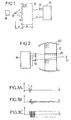
- the figure 1 shows the multi-diffuser medium 10 interposed between a source 12, which constitutes a target situated at a location where the concentration will take place, and an array of transceiver transducers 14 connected to a circuit 16 having as many transmission paths -reception that there are transducers.
- This circuit 16 has a constitution of the kind already described in the documents EP-A-0 383 650 and EP-A-0 591 061 .
- the tests were carried out with a target 12 constituted by a hydrophone provided with an excitation circuit 18 and capable of emitting short pulses, of 1 microsecond, with a central frequency of 3 MHz.
- the multi-diffuser medium 10 consists of rods 0.5 mm in length, with an average spacing of the order of 2 mm.
- the thickness e of the medium was 45 mm.
- the width w was of the order of 120 mm.
- Circuit 16 included, for each channel, an analog-digital converter, a memory organized in Queue and reading means with reverse chronology and amplification.
- a measurement of the characteristics of the return wave that has passed through the medium 10 has shown that the beam refocuses on an area having a width, at -6 dB, substantially equal to ⁇ F / w, where F is the distance between the exit plane of the multi-diffuser medium and the target.
- This focal spot is finer than it would have been in the absence of the multi-diffuser medium.
- the latter indeed has an angular aperture, seen from the target, much higher than the transducer array 14.
- the device schematically illustrated on the figure 2 (where the bodies corresponding to those already shown in figure 1 are designated by the same reference number) is intended to concentrate, on a passive target 12, a brief and intense pulse, with low power transmission means.
- a multi-diffuser medium 10 is interposed between the piezoelectric transducer array 14 and the target 12.
- the transducers 14, or at least some of them, are provided for sending to the target 12, which is reflective, a brief pulse at the frequency of the acoustic waves to be concentrated. It is also possible to use different transducers for the first illumination (step (a) above) and for reception and re-transmission (steps (b) and (c)).
- the multi-diffuser medium 10 is provided an opening 20 of sufficient size to allow the passage of a brief illumination firing, without diffusion. The illuminated target returns, to the multi-diffuser medium 10 and the transducer array 14, the wave which is then returned temporally.
- the wave received and reflected by the target 12 can have the variation in time shown schematically in figure 3A .
- This type of signal a few basic and broadband periods, can be obtained in particular using transducers in composite technology.
- the echo signal received by a particular transducer will then have, because a part of the less than the reflected energy has undergone multi-diffusion, a pace that is for example that shown on the figure 3B .
- means such as mirrors 22 may be arranged around the multi-diffuser medium 10, so as to reduce the re-emission of acoustic energy to directions other than that of the target and / or or to constitute an acoustic channel.
- the signal returned by each transducer 14 is not obtained by analog amplification of the returned signal, but by return of a signal consisting of alternately positive and negative pulses, each having the same duration and the same sign that the corresponding alternation ( figure 3C ).
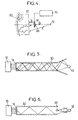
- the multi-diffuser medium 10 is placed opposite the target 12 relative to the transducer array 14.
- the first illumination is performed by an additional transmitter 24 (in the direction f0 of the figure 4 ).
- the acoustic energy reflected by the target 12 passes twice through the medium 10, with an intermediate reflection on a mirror 26, as indicated by the arrow f1.
- the network 14 also re-transmits towards the mirror 26 (arrow f2).
- step (a) it is sought to concentrate energy in a predetermined area of space, the target component, which has previously been selected.
- step (a) can only be performed during a calibration phase. Subsequently, the energy concentration is performed by repeating step (c).
- This last embodiment allows in particular to transmit messages that can be received with a high power and intelligibly in a specific area.
- the multi-diffuser medium must then be completely stationary.
- the amplifier provided on the channel associated with the transducer i will be provided so that the emission by the transducer is of the form ei ( ⁇ -t) ⁇ s (t), ⁇ being a fixed delay, identical for all the transducers.
- the demodulation will be performed in a conventional manner, regardless of the modulation of the signal s (t).
- the array of transducers may be unfocused with respect to the target and oriented towards a wall of the underwater acoustic channel, such as the surface or the bottom.
- the multi-diffuser medium 30 does not comprise randomly distributed elements in the volume of the propagation medium, but only reflective elements distributed on its surface, thus defining a channel or acoustic waveguide.
- the array of transducers 14 is placed at one end of this waveguide.
- the calibration source 12 is placed at the other end of the waveguide 30.
- the numerous reflections on the reflecting wall spread the duration of the initial pulse at the level of the grating 14, and inversely compress this duration during the focused re-emission to the location initially occupied by the calibration source.
- a transducer 24 is placed near the end of the waveguide 30 to illuminate the reflecting target 12 in the opposite direction to the guide 30 during the initial step.
- the transducer 24 can be fixed by means of a frame which does not impede the propagation of the waves, such as three wires oriented radially with respect to the axis of the guide, at 120 ° from each other.
- the portion of the short illumination beam returned by the target 12 to the guide 30 then undergoes multiple reflections that spread its duration. After time reversal and amplification, the energy will focus on the reflecting target 12 if it has not moved too much.
- Transducers and an associated circuit will not be described here in a complete manner, making it possible to implement the methods mentioned above. Indeed, the constitution of the circuits can be similar to that already given in the earlier patent applications mentioned above. It is only necessary that the queued memories for recording the complex signal received by the transducers 14 have sufficient capacity. The capacity of these memories will have to be further increased if it is desired to store the waveforms previously recorded relative to several distinct locations, which can be selected at will in the re-transmission phases. The gain of the amplifiers provided on each transducer channel will be, for a given power to be concentrated, a function of the time spreading effected by the multi-scattering medium 10.
Landscapes
- Physics & Mathematics (AREA)
- Engineering & Computer Science (AREA)
- Acoustics & Sound (AREA)
- Signal Processing (AREA)
- Multimedia (AREA)
- Measurement Of Velocity Or Position Using Acoustic Or Ultrasonic Waves (AREA)
- Circuit For Audible Band Transducer (AREA)
- Obtaining Desirable Characteristics In Audible-Bandwidth Transducers (AREA)
- Surgical Instruments (AREA)
- Investigating Or Analyzing Materials By The Use Of Ultrasonic Waves (AREA)
Applications Claiming Priority (3)
| Application Number | Priority Date | Filing Date | Title |
|---|---|---|---|
| FR9508543 | 1995-07-13 | ||
| FR9508543 | 1995-07-13 | ||
| EP96925774A EP0842508B1 (fr) | 1995-07-13 | 1996-07-11 | Procede et dispositif de focalisation d'ondes acoustiques |
Related Parent Applications (2)
| Application Number | Title | Priority Date | Filing Date |
|---|---|---|---|
| EP96925774A Division EP0842508B1 (fr) | 1995-07-13 | 1996-07-11 | Procede et dispositif de focalisation d'ondes acoustiques |
| EP96925774.0 Division | 1997-01-30 |
Publications (3)
| Publication Number | Publication Date |
|---|---|
| EP0944035A2 EP0944035A2 (fr) | 1999-09-22 |
| EP0944035A3 EP0944035A3 (fr) | 2001-04-18 |
| EP0944035B1 true EP0944035B1 (fr) | 2011-03-30 |
Family
ID=9480993
Family Applications (2)
| Application Number | Title | Priority Date | Filing Date |
|---|---|---|---|
| EP99111417A Expired - Lifetime EP0944035B1 (fr) | 1995-07-13 | 1996-07-11 | Procédé et dispositif de focalisation d'ondes acoustiques |
| EP96925774A Expired - Lifetime EP0842508B1 (fr) | 1995-07-13 | 1996-07-11 | Procede et dispositif de focalisation d'ondes acoustiques |
Family Applications After (1)
| Application Number | Title | Priority Date | Filing Date |
|---|---|---|---|
| EP96925774A Expired - Lifetime EP0842508B1 (fr) | 1995-07-13 | 1996-07-11 | Procede et dispositif de focalisation d'ondes acoustiques |
Country Status (5)
| Country | Link |
|---|---|
| US (2) | US6198829B1 (OSRAM) |
| EP (2) | EP0944035B1 (OSRAM) |
| JP (1) | JP3675836B2 (OSRAM) |
| DE (2) | DE69606179T2 (OSRAM) |
| WO (1) | WO1997003438A1 (OSRAM) |
Cited By (1)
| Publication number | Priority date | Publication date | Assignee | Title |
|---|---|---|---|---|
| US9436284B2 (en) | 2012-06-06 | 2016-09-06 | Commissariat A L'energie Atomique Et Aux Energies Alternatives | Time-reversal tactile stimulation interface |
Families Citing this family (17)
| Publication number | Priority date | Publication date | Assignee | Title |
|---|---|---|---|---|
| JP3675836B2 (ja) * | 1995-07-13 | 2005-07-27 | ソシエテ プール レ アプリカシオン デュ ルトゥールヌマン タンポレル | 音響波のフォーカス方法及び装置 |
| FR2815717B1 (fr) * | 2000-10-20 | 2003-01-10 | Centre Nat Rech Scient | Procede et dispositif non invasif de focalisation d'ondes acoustiques |
| FR2830468B1 (fr) * | 2001-10-04 | 2004-02-20 | Inst Nat Sante Rech Med | Dispositif et procede de production d'impulsions ultrasonores de forte pression |
| FR2840418B1 (fr) * | 2002-06-04 | 2004-08-20 | Centre Nat Rech Scient | Procede pour generer un champ d'ondes predetermine |
| US20040059265A1 (en) * | 2002-09-12 | 2004-03-25 | The Regents Of The University Of California | Dynamic acoustic focusing utilizing time reversal |
| FR2858099B1 (fr) * | 2003-07-25 | 2006-03-24 | Centre Nat Rech Scient | Procede et dispositif de focalisation d'ondes acoustiques |
| JP4629727B2 (ja) * | 2004-04-16 | 2011-02-09 | レイセオン カンパニー | スイマー(泳者)拒否のための方法およびシステム |
| FI20060910A7 (fi) * | 2006-03-28 | 2008-01-10 | Genelec Oy | Tunnistusmenetelmä ja -laitteisto äänentoistojärjestelmässä |
| FR2912817B1 (fr) * | 2007-02-21 | 2009-05-22 | Super Sonic Imagine Sa | Procede d'optimisation de la focalisation d'ondes au travers d'un element introducteur d'aberations. |
| US7613076B2 (en) * | 2007-05-31 | 2009-11-03 | Avago Technologies Wireless Ip (Singapore) Pte. Ltd. | Acoustic power transformer including lens |
| EP2260648B1 (en) | 2008-04-09 | 2013-01-09 | Fraunhofer-Gesellschaft zur Förderung der angewandten Forschung e.V. | Apparatus and method for generating filter characteristics |
| TW201026009A (en) * | 2008-12-30 | 2010-07-01 | Ind Tech Res Inst | An electrical apparatus, circuit for receiving audio and method for filtering noise |
| FR2977671B1 (fr) * | 2011-07-08 | 2013-11-29 | 01Db Metravib | Procede et dispositif pour controler des structures par retournement temporel |
| FR2991807B1 (fr) * | 2012-06-06 | 2014-08-29 | Centre Nat Rech Scient | Dispositif et procede de focalisation d'impulsions |
| FR3076940B1 (fr) * | 2018-01-12 | 2021-04-16 | Valeo Systemes Dessuyage | Procede d'emission sonore focalisee et systeme de focalisation acoustique |
| FR3076941B1 (fr) * | 2018-01-12 | 2021-06-04 | Valeo Systemes Dessuyage | Procede de calibration pour systeme de focalisation acoustique |
| KR102711302B1 (ko) * | 2023-08-09 | 2024-09-30 | 한국해양과학기술원 | 지뢰 탐지 장치, 이를 이용한 지뢰 탐지 방법 및 기록매체 |
Family Cites Families (22)
| Publication number | Priority date | Publication date | Assignee | Title |
|---|---|---|---|---|
| FR2334953A1 (fr) * | 1975-12-11 | 1977-07-08 | Labo Electronique Physique | Systeme d'analyse par ultrasons et son application a l'echographie |
| US4882714A (en) * | 1984-02-07 | 1989-11-21 | Nec Corporation | Object detecting system using ultrasonic waves |
| FR2642640B1 (fr) * | 1989-02-08 | 1991-05-10 | Centre Nat Rech Scient | Procede et dispositif de focalisation d'ultrasons dans les tissus |
| US5267320A (en) * | 1991-03-12 | 1993-11-30 | Ricoh Company, Ltd. | Noise controller which noise-controls movable point |
| FR2683323B1 (fr) | 1991-11-05 | 1994-02-11 | Paris Vii Universite | Procede et dispositif de controle interne de pieces par ultrasons. |
| FR2696573B1 (fr) * | 1992-10-02 | 1996-08-30 | Univ Paris | Procede et dispositif d'examen acoustique a retournement temporel. |
| FR2699205B1 (fr) * | 1992-12-11 | 1995-03-10 | Decaux Jean Claude | Perfectionnements aux procédés et dispositifs pour protéger des bruits extérieurs un volume donné, de préférence disposé à l'intérieur d'un local. |
| WO1994024662A1 (en) * | 1993-04-21 | 1994-10-27 | Sri International | Method of calculating filter weights for compression wave cancellation systems |
| US5327496A (en) * | 1993-06-30 | 1994-07-05 | Iowa State University Research Foundation, Inc. | Communication device, apparatus, and method utilizing pseudonoise signal for acoustical echo cancellation |
| FR2726115B1 (fr) * | 1994-10-20 | 1996-12-06 | Comptoir De La Technologie | Dispositif actif d'attenuation de l'intensite sonore |
| US5745580A (en) * | 1994-11-04 | 1998-04-28 | Lord Corporation | Reduction of computational burden of adaptively updating control filter(s) in active systems |
| JP3675836B2 (ja) * | 1995-07-13 | 2005-07-27 | ソシエテ プール レ アプリカシオン デュ ルトゥールヌマン タンポレル | 音響波のフォーカス方法及び装置 |
| US5699437A (en) * | 1995-08-29 | 1997-12-16 | United Technologies Corporation | Active noise control system using phased-array sensors |
| JPH09303477A (ja) * | 1996-05-16 | 1997-11-25 | Nissan Motor Co Ltd | 能動型騒音振動制御装置 |
| FR2749938B1 (fr) * | 1996-06-13 | 1998-08-28 | Fink Mathias | Procede et dispositif de detection et de localisation de source sonore reflechissante |
| US5963651A (en) * | 1997-01-16 | 1999-10-05 | Digisonix, Inc. | Adaptive acoustic attenuation system having distributed processing and shared state nodal architecture |
| US6292433B1 (en) * | 1997-02-03 | 2001-09-18 | Teratech Corporation | Multi-dimensional beamforming device |
| US5978489A (en) * | 1997-05-05 | 1999-11-02 | Oregon Graduate Institute Of Science And Technology | Multi-actuator system for active sound and vibration cancellation |
| EP1330815A2 (en) * | 2000-03-15 | 2003-07-30 | The Regents Of The University Of California | Method and apparatus for dynamic focusing of ultrasound energy |
| US6449566B1 (en) * | 2000-11-06 | 2002-09-10 | The United States Of America As Represented By The Secretary Of The Navy | Acoustic scattering measurement and processing for determining variances in multiple features |
| US6755083B2 (en) * | 2001-06-13 | 2004-06-29 | The Regents Of The University Of California | Method for distinguishing multiple targets using time-reversal acoustics |
| US6687188B2 (en) * | 2002-05-14 | 2004-02-03 | The United States Of America As Represented By The Secretary Of The Navy | Underwater telemetry apparatus and method |
-
1996
- 1996-07-11 JP JP50556897A patent/JP3675836B2/ja not_active Expired - Lifetime
- 1996-07-11 DE DE69606179T patent/DE69606179T2/de not_active Expired - Lifetime
- 1996-07-11 WO PCT/FR1996/001083 patent/WO1997003438A1/fr not_active Ceased
- 1996-07-11 EP EP99111417A patent/EP0944035B1/fr not_active Expired - Lifetime
- 1996-07-11 DE DE69638347T patent/DE69638347D1/de not_active Expired - Lifetime
- 1996-07-11 EP EP96925774A patent/EP0842508B1/fr not_active Expired - Lifetime
-
1998
- 1998-01-09 US US09/004,927 patent/US6198829B1/en not_active Expired - Lifetime
-
2000
- 2000-12-13 US US09/737,194 patent/US6978028B2/en not_active Expired - Lifetime
Cited By (1)
| Publication number | Priority date | Publication date | Assignee | Title |
|---|---|---|---|---|
| US9436284B2 (en) | 2012-06-06 | 2016-09-06 | Commissariat A L'energie Atomique Et Aux Energies Alternatives | Time-reversal tactile stimulation interface |
Also Published As
| Publication number | Publication date |
|---|---|
| EP0842508A1 (fr) | 1998-05-20 |
| EP0842508B1 (fr) | 2000-01-12 |
| JP2000501896A (ja) | 2000-02-15 |
| WO1997003438A1 (fr) | 1997-01-30 |
| US6978028B2 (en) | 2005-12-20 |
| DE69606179D1 (de) | 2000-02-17 |
| EP0944035A3 (fr) | 2001-04-18 |
| DE69638347D1 (de) | 2011-05-12 |
| US20010001603A1 (en) | 2001-05-24 |
| DE69606179T2 (de) | 2000-08-17 |
| EP0944035A2 (fr) | 1999-09-22 |
| US6198829B1 (en) | 2001-03-06 |
| JP3675836B2 (ja) | 2005-07-27 |
Similar Documents
| Publication | Publication Date | Title |
|---|---|---|
| EP0944035B1 (fr) | Procédé et dispositif de focalisation d'ondes acoustiques | |
| EP0383650B1 (fr) | Procédé et dispositif de repérage et de focalisation d'ondes | |
| EP0591061B1 (fr) | Procédé et dispositif d'examen acoustique à retournement temporel | |
| EP0459583B1 (fr) | Echographe ultrasonore à correction adaptative d'aberration de phase | |
| CA2874836A1 (fr) | Dispositif et procede de focalisation d'impulsions. | |
| CA2777036A1 (fr) | Dispositif de mesure de la vitesse du vent | |
| EP0733408B1 (fr) | Capteur à ultrasons et procédés de détection utilisant un tel capteur | |
| EP2084702B1 (fr) | Procede de generation d'ondes mecaniques par generation de force de radiation acoustique interfaciale | |
| EP2039021B1 (fr) | Procede et dispositif de transmission d'ondes | |
| EP1407292B1 (fr) | Sonar d'imagerie et systeme de detection utilisant un tel sonar | |
| EP1649449B1 (fr) | Procédé et dispositif d'imagerie par ondes acoustiques | |
| EP0632920B1 (fr) | Appareil de therapie a focalisation variable sans focalisation secondaire | |
| FR2822548A1 (fr) | Dispositif destine a la detection, la classification et l'identification des objets enfouis | |
| EP3871001A1 (fr) | Procede d'utilisation d'un sonar actif a large bande spectrale d'emission et systeme sonar | |
| WO2016055736A1 (fr) | Procédé de génération de rayonnements électromagnétiques haute puissance | |
| BE542461A (OSRAM) | ||
| FR2743894A1 (fr) | Dispositif de mesure angulaire de la position d'une cible pour radar a impulsions electromagnetiques transitoires et radar en faisant application | |
| EP0351267A1 (fr) | Dispositif et procédé d'identification passif interrogeable à distance | |
| FR2476360A1 (OSRAM) | ||
| FR2731866A1 (fr) | Antenne acoustique lineaire a balayage electronique | |
| FR2600774A1 (fr) | Dispositif pour barrette lineaire de transducteurs piezoelectriques destine a un echographe ultrasonore a resolution laterale amelioree | |
| WO2009112713A1 (fr) | Appareil a fonctionnement radar pour la detection et la localisation de discontinuites ou de corps etrangers dans les materiaux |
Legal Events
| Date | Code | Title | Description |
|---|---|---|---|
| PUAI | Public reference made under article 153(3) epc to a published international application that has entered the european phase |
Free format text: ORIGINAL CODE: 0009012 |
|
| 17P | Request for examination filed |
Effective date: 19990611 |
|
| AC | Divisional application: reference to earlier application |
Ref document number: 842508 Country of ref document: EP |
|
| AK | Designated contracting states |
Kind code of ref document: A2 Designated state(s): DE FR GB IT |
|
| RIN1 | Information on inventor provided before grant (corrected) |
Inventor name: LEWINER, JACQUES Inventor name: FINK, MATHIAS |
|
| PUAL | Search report despatched |
Free format text: ORIGINAL CODE: 0009013 |
|
| AK | Designated contracting states |
Kind code of ref document: A3 Designated state(s): DE FR GB IT |
|
| 17Q | First examination report despatched |
Effective date: 20060905 |
|
| GRAP | Despatch of communication of intention to grant a patent |
Free format text: ORIGINAL CODE: EPIDOSNIGR1 |
|
| GRAC | Information related to communication of intention to grant a patent modified |
Free format text: ORIGINAL CODE: EPIDOSCIGR1 |
|
| GRAC | Information related to communication of intention to grant a patent modified |
Free format text: ORIGINAL CODE: EPIDOSCIGR1 |
|
| GRAS | Grant fee paid |
Free format text: ORIGINAL CODE: EPIDOSNIGR3 |
|
| GRAA | (expected) grant |
Free format text: ORIGINAL CODE: 0009210 |
|
| AC | Divisional application: reference to earlier application |
Ref document number: 0842508 Country of ref document: EP Kind code of ref document: P |
|
| AK | Designated contracting states |
Kind code of ref document: B1 Designated state(s): DE FR GB IT |
|
| REG | Reference to a national code |
Ref country code: GB Ref legal event code: FG4D Free format text: NOT ENGLISH |
|
| REF | Corresponds to: |
Ref document number: 69638347 Country of ref document: DE Date of ref document: 20110512 Kind code of ref document: P |
|
| REG | Reference to a national code |
Ref country code: DE Ref legal event code: R096 Ref document number: 69638347 Country of ref document: DE Effective date: 20110512 |
|
| PLBE | No opposition filed within time limit |
Free format text: ORIGINAL CODE: 0009261 |
|
| STAA | Information on the status of an ep patent application or granted ep patent |
Free format text: STATUS: NO OPPOSITION FILED WITHIN TIME LIMIT |
|
| 26N | No opposition filed |
Effective date: 20120102 |
|
| REG | Reference to a national code |
Ref country code: DE Ref legal event code: R097 Ref document number: 69638347 Country of ref document: DE Effective date: 20120102 |
|
| REG | Reference to a national code |
Ref country code: FR Ref legal event code: PLFP Year of fee payment: 20 |
|
| PGFP | Annual fee paid to national office [announced via postgrant information from national office to epo] |
Ref country code: GB Payment date: 20150626 Year of fee payment: 20 |
|
| PGFP | Annual fee paid to national office [announced via postgrant information from national office to epo] |
Ref country code: FR Payment date: 20150625 Year of fee payment: 20 |
|
| PGFP | Annual fee paid to national office [announced via postgrant information from national office to epo] |
Ref country code: DE Payment date: 20150623 Year of fee payment: 20 |
|
| PGFP | Annual fee paid to national office [announced via postgrant information from national office to epo] |
Ref country code: IT Payment date: 20150629 Year of fee payment: 20 |
|
| REG | Reference to a national code |
Ref country code: DE Ref legal event code: R071 Ref document number: 69638347 Country of ref document: DE |
|
| REG | Reference to a national code |
Ref country code: GB Ref legal event code: PE20 Expiry date: 20160710 |
|
| PG25 | Lapsed in a contracting state [announced via postgrant information from national office to epo] |
Ref country code: GB Free format text: LAPSE BECAUSE OF EXPIRATION OF PROTECTION Effective date: 20160710 |