EP0943772A2 - Structure for mounting sliding doors - Google Patents
Structure for mounting sliding doors Download PDFInfo
- Publication number
- EP0943772A2 EP0943772A2 EP99500036A EP99500036A EP0943772A2 EP 0943772 A2 EP0943772 A2 EP 0943772A2 EP 99500036 A EP99500036 A EP 99500036A EP 99500036 A EP99500036 A EP 99500036A EP 0943772 A2 EP0943772 A2 EP 0943772A2
- Authority
- EP
- European Patent Office
- Prior art keywords
- bar
- shaped part
- screw
- bolt
- flaps
- Prior art date
- Legal status (The legal status is an assumption and is not a legal conclusion. Google has not performed a legal analysis and makes no representation as to the accuracy of the status listed.)
- Granted
Links
Images

Classifications
-
- E—FIXED CONSTRUCTIONS
- E05—LOCKS; KEYS; WINDOW OR DOOR FITTINGS; SAFES
- E05D—HINGES OR SUSPENSION DEVICES FOR DOORS, WINDOWS OR WINGS
- E05D15/00—Suspension arrangements for wings
- E05D15/06—Suspension arrangements for wings for wings sliding horizontally more or less in their own plane
- E05D15/0621—Details, e.g. suspension or supporting guides
- E05D15/0626—Details, e.g. suspension or supporting guides for wings suspended at the top
- E05D15/063—Details, e.g. suspension or supporting guides for wings suspended at the top on wheels with fixed axis
-
- E—FIXED CONSTRUCTIONS
- E05—LOCKS; KEYS; WINDOW OR DOOR FITTINGS; SAFES
- E05Y—INDEXING SCHEME RELATING TO HINGES OR OTHER SUSPENSION DEVICES FOR DOORS, WINDOWS OR WINGS AND DEVICES FOR MOVING WINGS INTO OPEN OR CLOSED POSITION, CHECKS FOR WINGS AND WING FITTINGS NOT OTHERWISE PROVIDED FOR, CONCERNED WITH THE FUNCTIONING OF THE WING
- E05Y2900/00—Application of doors, windows, wings or fittings thereof
- E05Y2900/20—Application of doors, windows, wings or fittings thereof for furnitures, e.g. cabinets
Definitions
- the present invention refers to improvements in invention patent no. 9501409 regarding a structure for mounting sliding doors, particularly sliding doors used in closing spaces for cupboards and the like.
- the structure described in patent no. 9501409 comprises an upper tubular support rail and a lower guide.
- the bottom of the upper rail is open longitudinally with a groove that is limited on the inside by tracks along which may slide moving carriages inside the rail. From these carriages hang the doors by intermediate support elements which consist of a U-bar, occluded in the door from its upper edge, and of a Z-shaped part which can slide inside said bar.
- the U-bar which makes up the intermediate support element is partially closed by opposed inner flaps.
- the Z-shaped part which may slide inside the U-bar has on one of its ends an orifice for the screw or bolt to attach the movable carriages.
- the Z-shaped part in the intermediate support element remains inside the U-bar of said element once the set is assembled.
- the object of the present invention is to eliminate the problems mentioned by a special arrangement of the intermediate support element, by which once the set is assembled and adjusted, the Z-shaped part in the intermediate support element is locked inside the U-bar. Thus the risk of the Z-shaped part sliding during opening or closing of the doors is eliminated.
- the U-bar of the intermediate support element from its longitudinal edge free of the two flaps which partially close the opening of this bar, and level with the position of the screw or bolt anchoring the Z-shaped bar in the door use position, has arched opposing notches which are sized to receive a ring mounted around the screw or bolt anchoring the Z-shaped part to the carriage, this ring being of an external diameter greater than the distance between the longitudinal edges of the flaps which partially close the U-bar.
- this ring may slide freely on the screw or bolt.
- the ring is raised or lowered on said screw or bolt, so that it is left above or below the longitudinal flaps which partially close the opening of the U-bar.
- the Z-shaped part may slide freely inside the U-bar until it reaches the desired position, which will be that of the opposed arched notches of the U-bar flaps, at which time the ring may move on the screw or bolt until it rests between said notches.
- the screw or bolt anchoring the Z-shaped part to the carriage is locked in place with respect to the U-bar, thus locking the position of the Z-shaped part.
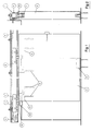
- Figure 1 is a longitudinal cross section of a structure for mounting sliding doors, in accordance with patent 9501409.
- Figure 2 is a side view of the same structure.
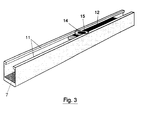
- Figure 3 is a perspective view of the intermediate support element according to the invention.
- Figure 4 is a top view of the U-bar of the intermediate support element.
- Figure 5 is a longitudinal cross section of the U-bar of figure 4.
- Figure 6 is a transversal cross section of the same bar, along the VI-VI line of figure 5.
- Figures 7 and 8 are longitudinal sections of the intermediate support element of the invention, with the Z-shaped part in an external adjustment and an internal operation position.
- FIG. 1 The structure shown in figures 1 and 2 consists of a support rail 1, of tubular construction, open along its lower side in a groove on both sides of which are inner tracks on which carriages 2 may travel, from which hang doors 4 by intermediate support elements 3. Inside rail 1 are mounted retainers 5 for carriages 2. Door 4 in carried from below by a guide 6.
- the intermediate support element 3 consists of a U-bar, shown in figures 4 to 6, labeled by number 7, which as can best be seen in figure 2, is embedded in door 4 from the upper edge of said door, and is attached by screws 8, figures 7 and 8, which can be introduced through orifices 9 and 10 made in the bottom of bar 7.
- Bar 7 is partially closed by longitudinal flaps 11.
- a Z-shaped part 12 which may move along the bar.
- One arm of the Z-shaped part has an orifice in its end for a screw or bolt 13 to attach it to carriages 2.
- the central orifice 9 at the bottom of bar 7 is shaped to house the head of screw 8 for attaching the door, while the end orifices 10 allow the pin of the screw to pass but do not house its head, which shall project out inside the bar to be used as a stop in limiting the displacement of the Z-shaped part 12 along bar 7.
- Figure 7 shows the Z-shaped part in an extreme position where it is partially projecting out of the bar, thus allowing it to act on the head of the anchoring screw or bolt 13, in order to adjust its height.
- Figure 8 shows piece 11 in its internal limit position corresponding to the position of operation of the door.
- bar 7 has opposing arched notches 14 from the longitudinal edge of the flaps 11, placed in the position to be occupied by bolt 13 in operation of the door.
- ring or washer 15 which may move freely on said screw and is of a diameter greater than the distance between the longitudinal cuts of flaps 11 of bar 7, and equal to or slightly smaller than the diameter of the outline defined by notches 14.
Abstract


Description
- The present invention refers to improvements in invention patent no. 9501409 regarding a structure for mounting sliding doors, particularly sliding doors used in closing spaces for cupboards and the like.
- The structure described in patent no. 9501409 comprises an upper tubular support rail and a lower guide. The bottom of the upper rail is open longitudinally with a groove that is limited on the inside by tracks along which may slide moving carriages inside the rail. From these carriages hang the doors by intermediate support elements which consist of a U-bar, occluded in the door from its upper edge, and of a Z-shaped part which can slide inside said bar. The U-bar which makes up the intermediate support element is partially closed by opposed inner flaps. The Z-shaped part which may slide inside the U-bar has on one of its ends an orifice for the screw or bolt to attach the movable carriages.
- For the correct operation of the structure it is desirable that the Z-shaped part in the intermediate support element remains inside the U-bar of said element once the set is assembled.
- However, under certain conditions, such as when the doors are not very heavy, it may be that as the doors slide the Z-shaped part moves inside the U-bar until it is partially projecting out, along the branch crossed by the support screw or bolt to the movable carriages, thus leaving the head of this screw or bolt outside the U-bar. This situation could cause noises as the Z-shaped part moves, and mainly misadjustment of the screw or bolt to the carriage, with the negative effects which this would have on the operation of the door, forcing a new adjustment operation.
- The object of the present invention is to eliminate the problems mentioned by a special arrangement of the intermediate support element, by which once the set is assembled and adjusted, the Z-shaped part in the intermediate support element is locked inside the U-bar. Thus the risk of the Z-shaped part sliding during opening or closing of the doors is eliminated.
- The special arrangement of the intermediate support element will nevertheless allow freeing the Z-shaped part whenever desired in order to carry out adjustments, maintenance, etc.
- According to the present invention, the U-bar of the intermediate support element, from its longitudinal edge free of the two flaps which partially close the opening of this bar, and level with the position of the screw or bolt anchoring the Z-shaped bar in the door use position, has arched opposing notches which are sized to receive a ring mounted around the screw or bolt anchoring the Z-shaped part to the carriage, this ring being of an external diameter greater than the distance between the longitudinal edges of the flaps which partially close the U-bar. In addition, this ring may slide freely on the screw or bolt.
- With this arrangement, once the length of the screw or bolt anchoring the Z-shaped part to the carriage is adjusted, the ring is raised or lowered on said screw or bolt, so that it is left above or below the longitudinal flaps which partially close the opening of the U-bar. In this situation the Z-shaped part may slide freely inside the U-bar until it reaches the desired position, which will be that of the opposed arched notches of the U-bar flaps, at which time the ring may move on the screw or bolt until it rests between said notches. In this position the screw or bolt anchoring the Z-shaped part to the carriage is locked in place with respect to the U-bar, thus locking the position of the Z-shaped part.
- The characteristics and advantages set forth will be understood better with the following description, made with reference to the attached drawings, in which an example is shown of a non-limiting embodiment.
- In the drawings:
- Figure 1 is a longitudinal cross section of a structure for mounting sliding doors, in accordance with patent 9501409.
- Figure 2 is a side view of the same structure.
- Figure 3 is a perspective view of the intermediate support element according to the invention.
- Figure 4 is a top view of the U-bar of the intermediate support element.
- Figure 5 is a longitudinal cross section of the U-bar of figure 4.
- Figure 6 is a transversal cross section of the same bar, along the VI-VI line of figure 5.
- Figures 7 and 8 are longitudinal sections of the intermediate support element of the invention, with the Z-shaped part in an external adjustment and an internal operation position.
- The structure shown in figures 1 and 2 consists of a
support rail 1, of tubular construction, open along its lower side in a groove on both sides of which are inner tracks on whichcarriages 2 may travel, from which hang doors 4 byintermediate support elements 3. Insiderail 1 are mountedretainers 5 forcarriages 2. Door 4 in carried from below by aguide 6. - The
intermediate support element 3 consists of a U-bar, shown in figures 4 to 6, labeled bynumber 7, which as can best be seen in figure 2, is embedded in door 4 from the upper edge of said door, and is attached byscrews 8, figures 7 and 8, which can be introduced throughorifices bar 7. -
Bar 7 is partially closed bylongitudinal flaps 11. - Inside U-bar 7 is a Z-
shaped part 12 which may move along the bar. One arm of the Z-shaped part has an orifice in its end for a screw orbolt 13 to attach it tocarriages 2. As can be seen in figures 5, 7 and 8, thecentral orifice 9 at the bottom ofbar 7 is shaped to house the head ofscrew 8 for attaching the door, while theend orifices 10 allow the pin of the screw to pass but do not house its head, which shall project out inside the bar to be used as a stop in limiting the displacement of the Z-shaped part 12 alongbar 7. - Figure 7 shows the Z-shaped part in an extreme position where it is partially projecting out of the bar, thus allowing it to act on the head of the anchoring screw or
bolt 13, in order to adjust its height. Figure 8 showspiece 11 in its internal limit position corresponding to the position of operation of the door. - In order to lock this last position shown in figure 8, according to the invention,
bar 7 has opposingarched notches 14 from the longitudinal edge of theflaps 11, placed in the position to be occupied bybolt 13 in operation of the door. - Above the anchoring bolt or
screw 13 is mounted a ring orwasher 15 which may move freely on said screw and is of a diameter greater than the distance between the longitudinal cuts offlaps 11 ofbar 7, and equal to or slightly smaller than the diameter of the outline defined bynotches 14. - With the arrangement described, once the height of
screw 13 has been adjusted for a correct positioning of the door, ring orwasher 15 is moved upwards or downwards so that it is above or below theflaps 11 ofbar 7. In this situation Z-shaped part 11 can move into thebar 7, until the position shown in figure 8 is reached, at which time ring orwasher 15 is placed betweennotches 14, thus lockingpart 12 preventing any longitudinal motion. - By correct sizing of
notches 14 and the diameter and thickness of ring orwasher 15, the position of figure 8 is ascertained. When the Z-shaped part 12 has to be removed to make adjustments or for maintenance, it is enough to lift the leaf of the corresponding end for the washer to be placed underflaps 11, thus freeing Z-shaped part 12 to move into the extracted position of figure 7.
Claims (1)
- Structure for mounting sliding doors, which consists of at least one support tubular rail (1) which is open longitudinally along the bottom, defining inner longitudinal tracks on which may move carriages (2), from which hang doors (4) by intermediate support elements (3), these elements consisting of a U-bar (7) which is embedded in door (4) from its upper edge, and of a Z-shaped part (12) which can slide inside the U-bar (7), this U-bar being partially closed longitudinally by inner opposing flaps (11), and Z-shaped part (12) having in one of its end arms an orifice for a screw or bolt (13) anchoring the movable carriages (2), characterised in that the U-bar (7) of the intermediate support element (3), from its longitudinal edge free of the two flaps (11) which partially close the opening of this bar, and level with the position of the screw or bolt (13) anchoring the Z-shaped part (12) to carriage (2) in the door (4) operation position, has arched opposing notches (14) which are sized to receive a ring (15) of an external diameter greater than the distance between the free longitudinal edges of said flaps (11), ring (15) being mounted around the screw or bolt (13)and free to move on it.
Applications Claiming Priority (2)
| Application Number | Priority Date | Filing Date | Title |
|---|---|---|---|
| ES009800481A ES2164498B1 (en) | 1995-07-13 | 1998-03-06 | IMPROVEMENTS INTRODUCED IN PATENT N- 9501409, RELATING TO A STRUCTURE FOR THE MOUNTING OF SLIDING DOORS. |
| ES9800481 | 1998-03-06 |
Publications (3)
| Publication Number | Publication Date |
|---|---|
| EP0943772A2 true EP0943772A2 (en) | 1999-09-22 |
| EP0943772A3 EP0943772A3 (en) | 2003-09-24 |
| EP0943772B1 EP0943772B1 (en) | 2005-02-09 |
Family
ID=8303018
Family Applications (1)
| Application Number | Title | Priority Date | Filing Date |
|---|---|---|---|
| EP99500036A Expired - Lifetime EP0943772B1 (en) | 1998-03-06 | 1999-03-05 | Structure for mounting sliding doors |
Country Status (6)
| Country | Link |
|---|---|
| EP (1) | EP0943772B1 (en) |
| AT (1) | ATE288992T1 (en) |
| DE (1) | DE69923617T2 (en) |
| DK (1) | DK0943772T3 (en) |
| ES (1) | ES2237065T3 (en) |
| PT (1) | PT943772E (en) |
Cited By (7)
| Publication number | Priority date | Publication date | Assignee | Title |
|---|---|---|---|---|
| EP1741862A2 (en) * | 2005-06-27 | 2007-01-10 | Eclisse Srl | Support and anchorage device for sliding doors |
| US7246411B2 (en) | 2003-12-19 | 2007-07-24 | Jeld-Wen, Inc. | Methods and systems for sliding windows and doors |
| CN100375828C (en) * | 1999-12-10 | 2008-03-19 | 道尔玛有限公司和两合公司 | Sliding panel comprising several wall elements that can be displaced laterally |
| WO2011063535A1 (en) * | 2009-11-26 | 2011-06-03 | Eku Ag | Running mechanism for a sliding door |
| CN102979422A (en) * | 2012-11-23 | 2013-03-20 | 上海电机学院 | Glass window |
| EP3040501A1 (en) * | 2014-12-30 | 2016-07-06 | Eclisse Srl | Support |
| CN110214217A (en) * | 2017-03-22 | 2019-09-06 | 个人特诺斯科瑞沃里有限公司 | For making the device for the door sliding for being covered with industrial laminated product |
Citations (4)
| Publication number | Priority date | Publication date | Assignee | Title |
|---|---|---|---|---|
| CH379954A (en) * | 1960-05-09 | 1964-07-15 | Walz Fritz | Roller suspension system for sashes of sliding doors and windows that are guided on rails |
| CH430486A (en) * | 1965-12-01 | 1967-02-15 | Hawa Ag | Roller suspension for doors or windows |
| EP0753637A1 (en) * | 1995-07-13 | 1997-01-15 | Klein Iberica, S.A. | Structure for the assembly of sliding doors |
| EP0818598A1 (en) * | 1996-07-11 | 1998-01-14 | Hawa Ag | Fitting assembly for sliding elements |
-
1999
- 1999-03-05 PT PT99500036T patent/PT943772E/en unknown
- 1999-03-05 DK DK99500036T patent/DK0943772T3/en active
- 1999-03-05 ES ES99500036T patent/ES2237065T3/en not_active Expired - Lifetime
- 1999-03-05 EP EP99500036A patent/EP0943772B1/en not_active Expired - Lifetime
- 1999-03-05 AT AT99500036T patent/ATE288992T1/en active
- 1999-03-05 DE DE69923617T patent/DE69923617T2/en not_active Expired - Lifetime
Patent Citations (4)
| Publication number | Priority date | Publication date | Assignee | Title |
|---|---|---|---|---|
| CH379954A (en) * | 1960-05-09 | 1964-07-15 | Walz Fritz | Roller suspension system for sashes of sliding doors and windows that are guided on rails |
| CH430486A (en) * | 1965-12-01 | 1967-02-15 | Hawa Ag | Roller suspension for doors or windows |
| EP0753637A1 (en) * | 1995-07-13 | 1997-01-15 | Klein Iberica, S.A. | Structure for the assembly of sliding doors |
| EP0818598A1 (en) * | 1996-07-11 | 1998-01-14 | Hawa Ag | Fitting assembly for sliding elements |
Cited By (9)
| Publication number | Priority date | Publication date | Assignee | Title |
|---|---|---|---|---|
| CN100375828C (en) * | 1999-12-10 | 2008-03-19 | 道尔玛有限公司和两合公司 | Sliding panel comprising several wall elements that can be displaced laterally |
| US7246411B2 (en) | 2003-12-19 | 2007-07-24 | Jeld-Wen, Inc. | Methods and systems for sliding windows and doors |
| EP1741862A2 (en) * | 2005-06-27 | 2007-01-10 | Eclisse Srl | Support and anchorage device for sliding doors |
| EP1741862A3 (en) * | 2005-06-27 | 2008-02-27 | Eclisse Srl | Support and anchorage device for sliding doors |
| WO2011063535A1 (en) * | 2009-11-26 | 2011-06-03 | Eku Ag | Running mechanism for a sliding door |
| CN102979422A (en) * | 2012-11-23 | 2013-03-20 | 上海电机学院 | Glass window |
| EP3040501A1 (en) * | 2014-12-30 | 2016-07-06 | Eclisse Srl | Support |
| CN110214217A (en) * | 2017-03-22 | 2019-09-06 | 个人特诺斯科瑞沃里有限公司 | For making the device for the door sliding for being covered with industrial laminated product |
| CN110214217B (en) * | 2017-03-22 | 2021-12-07 | 个人特诺斯科瑞沃里有限公司 | Device for sliding doors covered with industrial laminates |
Also Published As
| Publication number | Publication date |
|---|---|
| ATE288992T1 (en) | 2005-02-15 |
| DE69923617D1 (en) | 2005-03-17 |
| DE69923617T2 (en) | 2006-01-05 |
| DK0943772T3 (en) | 2005-06-06 |
| EP0943772B1 (en) | 2005-02-09 |
| PT943772E (en) | 2005-06-30 |
| EP0943772A3 (en) | 2003-09-24 |
| ES2237065T3 (en) | 2005-07-16 |
Similar Documents
| Publication | Publication Date | Title |
|---|---|---|
| EP2546440A2 (en) | Bogey assembly | |
| DE3101725A1 (en) | "SLIDING DOOR SYSTEM" | |
| DE3336739A1 (en) | Closing-sequence device for a two-wing door | |
| EP0943772B1 (en) | Structure for mounting sliding doors | |
| EP0733766B1 (en) | Suspension device for a slidable element | |
| EP3668350B1 (en) | Drawer pull-out guide | |
| DE20118906U1 (en) | Locking and securing device for a wing of a lifting and sliding door and / or a lifting and sliding window, connecting rod fitting for a lifting and sliding door and / or a lifting and sliding window and lifting and sliding door or window with such a locking and safety device | |
| EP0972885B1 (en) | Tilting roof window | |
| DE102019211790A1 (en) | Barrier-free sliding window, barrier-free sliding door and lower hardware arrangement | |
| DE4308560A1 (en) | Closing-sequence control for a door self-closing via door closers and comprising a standing wing and a passage wing | |
| EP3688260B1 (en) | A window or door fitting which can be latched in the tilted position but is nevertheless easily movable during a slide closing process | |
| DE19913413B4 (en) | Overhead | |
| DE102004046997A1 (en) | Method for fitting room divider panels especially for sanitary cubicles with integral slide block adjusters for alignment | |
| DE19717070C1 (en) | Skylights, in particular swing-wing skylights | |
| DE3723408C2 (en) | ||
| EP3480407A1 (en) | Vertical pushing element | |
| DE19731932C2 (en) | Sectional gate for particularly low lintel heights | |
| WO1998051895A1 (en) | Sliding door | |
| EP1281655B1 (en) | Landing door | |
| DE20180385U1 (en) | Open roof construction for a vehicle | |
| EP2460967A2 (en) | Side sectional door and distance compensation device | |
| DE102011085742B4 (en) | Web-controlled adjusting device with a multi-part carrier assembly | |
| DE102019211796A1 (en) | Guide fitting for a sliding sash arrangement, sliding sash arrangement and method for assembling a sliding sash arrangement | |
| EP1312741B1 (en) | Pivoting or pivoting-and-tilting fitting for windows and doors with a rotation-damping device | |
| DE19914319A1 (en) | Shower partition has fixed side part and movable panel moving in guide rail set inside fitting above side part and with height adjustment device |
Legal Events
| Date | Code | Title | Description |
|---|---|---|---|
| PUAI | Public reference made under article 153(3) epc to a published international application that has entered the european phase |
Free format text: ORIGINAL CODE: 0009012 |
|
| AK | Designated contracting states |
Kind code of ref document: A2 Designated state(s): AT BE CH CY DE DK ES FI FR GB GR IE IT LI LU MC NL PT SE |
|
| AX | Request for extension of the european patent |
Free format text: AL;LT;LV;MK;RO;SI |
|
| PUAL | Search report despatched |
Free format text: ORIGINAL CODE: 0009013 |
|
| AK | Designated contracting states |
Kind code of ref document: A3 Designated state(s): AT BE CH CY DE DK ES FI FR GB GR IE IT LI LU MC NL PT SE |
|
| AX | Request for extension of the european patent |
Extension state: AL LT LV MK RO SI |
|
| 17P | Request for examination filed |
Effective date: 20031224 |
|
| GRAP | Despatch of communication of intention to grant a patent |
Free format text: ORIGINAL CODE: EPIDOSNIGR1 |
|
| AKX | Designation fees paid |
Designated state(s): AT BE CH CY DE DK ES FI FR GB GR IE IT LI LU MC NL PT SE |
|
| AXX | Extension fees paid |
Extension state: SI Payment date: 20031224 Extension state: RO Payment date: 20031224 Extension state: LV Payment date: 20031224 Extension state: LT Payment date: 20031224 |
|
| GRAS | Grant fee paid |
Free format text: ORIGINAL CODE: EPIDOSNIGR3 |
|
| GRAA | (expected) grant |
Free format text: ORIGINAL CODE: 0009210 |
|
| AK | Designated contracting states |
Kind code of ref document: B1 Designated state(s): AT BE CH CY DE DK ES FI FR GB GR IE IT LI LU MC NL PT SE |
|
| AX | Request for extension of the european patent |
Extension state: LT LV RO SI |
|
| REG | Reference to a national code |
Ref country code: GB Ref legal event code: FG4D |
|
| REG | Reference to a national code |
Ref country code: CH Ref legal event code: EP |
|
| PG25 | Lapsed in a contracting state [announced via postgrant information from national office to epo] |
Ref country code: CY Free format text: LAPSE BECAUSE OF FAILURE TO SUBMIT A TRANSLATION OF THE DESCRIPTION OR TO PAY THE FEE WITHIN THE PRESCRIBED TIME-LIMIT Effective date: 20050305 |
|
| REG | Reference to a national code |
Ref country code: IE Ref legal event code: FG4D |
|
| REF | Corresponds to: |
Ref document number: 69923617 Country of ref document: DE Date of ref document: 20050317 Kind code of ref document: P |
|
| REG | Reference to a national code |
Ref country code: SE Ref legal event code: TRGR |
|
| REG | Reference to a national code |
Ref country code: GR Ref legal event code: EP Ref document number: 20050401410 Country of ref document: GR |
|
| REG | Reference to a national code |
Ref country code: CH Ref legal event code: NV Representative=s name: MICHELI & CIE INGENIEURS-CONSEILS |
|
| REG | Reference to a national code |
Ref country code: DK Ref legal event code: T3 |
|
| REG | Reference to a national code |
Ref country code: PT Ref legal event code: SC4A Free format text: AVAILABILITY OF NATIONAL TRANSLATION Effective date: 20050505 |
|
| REG | Reference to a national code |
Ref country code: ES Ref legal event code: FG2A Ref document number: 2237065 Country of ref document: ES Kind code of ref document: T3 |
|
| LTIE | Lt: invalidation of european patent or patent extension |
Effective date: 20050209 |
|
| PLBE | No opposition filed within time limit |
Free format text: ORIGINAL CODE: 0009261 |
|
| STAA | Information on the status of an ep patent application or granted ep patent |
Free format text: STATUS: NO OPPOSITION FILED WITHIN TIME LIMIT |
|
| 26N | No opposition filed |
Effective date: 20051110 |
|
| ET | Fr: translation filed | ||
| REG | Reference to a national code |
Ref country code: FR Ref legal event code: PLFP Year of fee payment: 18 |
|
| REG | Reference to a national code |
Ref country code: FR Ref legal event code: PLFP Year of fee payment: 19 |
|
| REG | Reference to a national code |
Ref country code: FR Ref legal event code: PLFP Year of fee payment: 20 |
|
| PGFP | Annual fee paid to national office [announced via postgrant information from national office to epo] |
Ref country code: FI Payment date: 20180312 Year of fee payment: 20 Ref country code: LU Payment date: 20180226 Year of fee payment: 20 Ref country code: GB Payment date: 20180228 Year of fee payment: 20 Ref country code: DK Payment date: 20180312 Year of fee payment: 20 Ref country code: DE Payment date: 20180227 Year of fee payment: 20 Ref country code: CH Payment date: 20180314 Year of fee payment: 20 Ref country code: NL Payment date: 20180314 Year of fee payment: 20 |
|
| PGFP | Annual fee paid to national office [announced via postgrant information from national office to epo] |
Ref country code: GR Payment date: 20180227 Year of fee payment: 20 Ref country code: SE Payment date: 20180313 Year of fee payment: 20 Ref country code: BE Payment date: 20180223 Year of fee payment: 20 Ref country code: FR Payment date: 20180227 Year of fee payment: 20 Ref country code: PT Payment date: 20180219 Year of fee payment: 20 Ref country code: IE Payment date: 20180312 Year of fee payment: 20 Ref country code: AT Payment date: 20180226 Year of fee payment: 20 Ref country code: IT Payment date: 20180301 Year of fee payment: 20 Ref country code: MC Payment date: 20180228 Year of fee payment: 20 |
|
| PGFP | Annual fee paid to national office [announced via postgrant information from national office to epo] |
Ref country code: ES Payment date: 20180410 Year of fee payment: 20 |
|
| REG | Reference to a national code |
Ref country code: DE Ref legal event code: R071 Ref document number: 69923617 Country of ref document: DE |
|
| REG | Reference to a national code |
Ref country code: NL Ref legal event code: MK Effective date: 20190304 |
|
| REG | Reference to a national code |
Ref country code: DK Ref legal event code: EUP Effective date: 20190305 |
|
| REG | Reference to a national code |
Ref country code: CH Ref legal event code: PL |
|
| REG | Reference to a national code |
Ref country code: GB Ref legal event code: PE20 Expiry date: 20190304 |
|
| REG | Reference to a national code |
Ref country code: BE Ref legal event code: MK Effective date: 20190305 |
|
| REG | Reference to a national code |
Ref country code: AT Ref legal event code: MK07 Ref document number: 288992 Country of ref document: AT Kind code of ref document: T Effective date: 20190305 |
|
| REG | Reference to a national code |
Ref country code: IE Ref legal event code: MK9A |
|
| PG25 | Lapsed in a contracting state [announced via postgrant information from national office to epo] |
Ref country code: GB Free format text: LAPSE BECAUSE OF EXPIRATION OF PROTECTION Effective date: 20190304 Ref country code: IE Free format text: LAPSE BECAUSE OF EXPIRATION OF PROTECTION Effective date: 20190305 |
|
| PG25 | Lapsed in a contracting state [announced via postgrant information from national office to epo] |
Ref country code: PT Free format text: LAPSE BECAUSE OF EXPIRATION OF PROTECTION Effective date: 20190314 |
|
| REG | Reference to a national code |
Ref country code: ES Ref legal event code: FD2A Effective date: 20200904 |
|
| PG25 | Lapsed in a contracting state [announced via postgrant information from national office to epo] |
Ref country code: ES Free format text: LAPSE BECAUSE OF EXPIRATION OF PROTECTION Effective date: 20190306 |