EP1312741B1 - Pivoting or pivoting-and-tilting fitting for windows and doors with a rotation-damping device - Google Patents
Pivoting or pivoting-and-tilting fitting for windows and doors with a rotation-damping device Download PDFInfo
- Publication number
- EP1312741B1 EP1312741B1 EP02022793A EP02022793A EP1312741B1 EP 1312741 B1 EP1312741 B1 EP 1312741B1 EP 02022793 A EP02022793 A EP 02022793A EP 02022793 A EP02022793 A EP 02022793A EP 1312741 B1 EP1312741 B1 EP 1312741B1
- Authority
- EP
- European Patent Office
- Prior art keywords
- fitting
- accordance
- plastic part
- bearing
- leaf
- Prior art date
- Legal status (The legal status is an assumption and is not a legal conclusion. Google has not performed a legal analysis and makes no representation as to the accuracy of the status listed.)
- Expired - Lifetime
Links
- 238000013016 damping Methods 0.000 title 1
- 238000009434 installation Methods 0.000 claims description 4
- 230000007704 transition Effects 0.000 claims description 2
- 230000000295 complement effect Effects 0.000 claims 1
- 230000002401 inhibitory effect Effects 0.000 description 10
- 239000000463 material Substances 0.000 description 3
- 230000003993 interaction Effects 0.000 description 2
- 230000009977 dual effect Effects 0.000 description 1
- 230000000694 effects Effects 0.000 description 1
- 230000010354 integration Effects 0.000 description 1
- 210000000056 organ Anatomy 0.000 description 1
- 229910000679 solder Inorganic materials 0.000 description 1
- 125000006850 spacer group Chemical group 0.000 description 1
Images


Classifications
-
- E—FIXED CONSTRUCTIONS
- E05—LOCKS; KEYS; WINDOW OR DOOR FITTINGS; SAFES
- E05F—DEVICES FOR MOVING WINGS INTO OPEN OR CLOSED POSITION; CHECKS FOR WINGS; WING FITTINGS NOT OTHERWISE PROVIDED FOR, CONCERNED WITH THE FUNCTIONING OF THE WING
- E05F7/00—Accessories for wings not provided for in other groups of this subclass
- E05F7/06—Devices for taking the weight of the wing, arranged away from the hinge axis
-
- E—FIXED CONSTRUCTIONS
- E05—LOCKS; KEYS; WINDOW OR DOOR FITTINGS; SAFES
- E05D—HINGES OR SUSPENSION DEVICES FOR DOORS, WINDOWS OR WINGS
- E05D11/00—Additional features or accessories of hinges
- E05D11/08—Friction devices between relatively-movable hinge parts
- E05D11/087—Friction devices between relatively-movable hinge parts with substantially axial friction, e.g. friction disks
-
- E—FIXED CONSTRUCTIONS
- E05—LOCKS; KEYS; WINDOW OR DOOR FITTINGS; SAFES
- E05D—HINGES OR SUSPENSION DEVICES FOR DOORS, WINDOWS OR WINGS
- E05D15/00—Suspension arrangements for wings
- E05D15/48—Suspension arrangements for wings allowing alternative movements
- E05D15/52—Suspension arrangements for wings allowing alternative movements for opening about a vertical as well as a horizontal axis
- E05D15/5214—Corner supports
-
- E—FIXED CONSTRUCTIONS
- E05—LOCKS; KEYS; WINDOW OR DOOR FITTINGS; SAFES
- E05Y—INDEXING SCHEME ASSOCIATED WITH SUBCLASSES E05D AND E05F, RELATING TO CONSTRUCTION ELEMENTS, ELECTRIC CONTROL, POWER SUPPLY, POWER SIGNAL OR TRANSMISSION, USER INTERFACES, MOUNTING OR COUPLING, DETAILS, ACCESSORIES, AUXILIARY OPERATIONS NOT OTHERWISE PROVIDED FOR, APPLICATION THEREOF
- E05Y2201/00—Constructional elements; Accessories therefor
- E05Y2201/20—Brakes; Disengaging means; Holders; Stops; Valves; Accessories therefor
- E05Y2201/21—Brakes
-
- E—FIXED CONSTRUCTIONS
- E05—LOCKS; KEYS; WINDOW OR DOOR FITTINGS; SAFES
- E05Y—INDEXING SCHEME ASSOCIATED WITH SUBCLASSES E05D AND E05F, RELATING TO CONSTRUCTION ELEMENTS, ELECTRIC CONTROL, POWER SUPPLY, POWER SIGNAL OR TRANSMISSION, USER INTERFACES, MOUNTING OR COUPLING, DETAILS, ACCESSORIES, AUXILIARY OPERATIONS NOT OTHERWISE PROVIDED FOR, APPLICATION THEREOF
- E05Y2201/00—Constructional elements; Accessories therefor
- E05Y2201/20—Brakes; Disengaging means; Holders; Stops; Valves; Accessories therefor
- E05Y2201/252—Type of friction
- E05Y2201/26—Mechanical friction
-
- E—FIXED CONSTRUCTIONS
- E05—LOCKS; KEYS; WINDOW OR DOOR FITTINGS; SAFES
- E05Y—INDEXING SCHEME ASSOCIATED WITH SUBCLASSES E05D AND E05F, RELATING TO CONSTRUCTION ELEMENTS, ELECTRIC CONTROL, POWER SUPPLY, POWER SIGNAL OR TRANSMISSION, USER INTERFACES, MOUNTING OR COUPLING, DETAILS, ACCESSORIES, AUXILIARY OPERATIONS NOT OTHERWISE PROVIDED FOR, APPLICATION THEREOF
- E05Y2900/00—Application of doors, windows, wings or fittings thereof
- E05Y2900/10—Application of doors, windows, wings or fittings thereof for buildings or parts thereof
- E05Y2900/13—Type of wing
- E05Y2900/132—Doors
-
- E—FIXED CONSTRUCTIONS
- E05—LOCKS; KEYS; WINDOW OR DOOR FITTINGS; SAFES
- E05Y—INDEXING SCHEME ASSOCIATED WITH SUBCLASSES E05D AND E05F, RELATING TO CONSTRUCTION ELEMENTS, ELECTRIC CONTROL, POWER SUPPLY, POWER SIGNAL OR TRANSMISSION, USER INTERFACES, MOUNTING OR COUPLING, DETAILS, ACCESSORIES, AUXILIARY OPERATIONS NOT OTHERWISE PROVIDED FOR, APPLICATION THEREOF
- E05Y2900/00—Application of doors, windows, wings or fittings thereof
- E05Y2900/10—Application of doors, windows, wings or fittings thereof for buildings or parts thereof
- E05Y2900/13—Type of wing
- E05Y2900/148—Windows
Definitions
- the invention relates to a turn or Drehkippbeschlag for windows or doors with a device for inhibiting pivotal movements of the wing according to the preamble of claim 1.
- a turn-tilt fitting is known in which at a pivot opening of the window sash an extension attached to the window sash runs on a stationary slideway, so that the sash is raised.
- the object of the invention is therefore, starting from the above-described problem and the prior art explained a rotary or Drehkippbeschlag the type entered in a particularly economical manner in such a way that the rotation inhibiting device with optimal integration in the fitting a high and durable Has effectiveness and at the same time can take over the function of a baking device according to a preferred development.
- the plastic part is given a double function, since it can fulfill the function of a baking device in addition to the rotation inhibiting function, so that a total of a casserole occurs, which is already installed in the factory and the fitting-processor no additional work on Wing and / or frame imposed. It is thus obtained a run-on sliding brake device with a minimum of material use with a maximum of effectiveness.
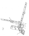
- Fig. 1 shows the lower corner bearing 1 of a rotary or rotary tilting fitting, which is designed for attachment to the frame.
- This corner bearing 1 has a preferably integrally formed bearing block 2, which on the back and in Fig. 1 is not visible a receptacle for a bearing pin 5 which is fixedly connected to a connecting leg 4, which in turn is fixedly attached to the wing fitting 3.
- the bearing pin 5 can perform in its recording in the bearing block 2 pivoting and tilting movements.
- a braking surface 6 is provided, which is formed on a plastic part 7, which is held positively and non-positively in a guide groove 8 of the bearing block 2.
- This braking surface 6 acts with the support surface 11 to be designated underside of the Connecting leg 4 together.
- the braking surface may optionally be formed spherical and / or have a predeterminable compressibility.
- the plastic part 7 has bevels on both sides with respect to the desired left-right stop, which cooperate with a corresponding inclined surface 10 on the connecting leg 4.
- the ramp 9 is first effective and raises the wing in the manner predefined by the plastic part 7, whereupon upon further pivoting of the wing, the braking surface. 6 takes effect, so that the wing stops in any desired open position and does not fall by itself in an open or closed position.
- This plastic part 7 can generally also be designed without run-on bevels 9, so that it acts as a braking surface only in all open positions as a braking surface ,
- the preferred embodiment has ramps 9, with the result that the rotation inhibiting device can fulfill the dual function of a run-on sliding brake device.
- FIG. 3 shows the engaging in a recess of the bearing block 2 bearing pin 5, which is connected via the connecting leg 4 with the wing fitting 3.
- the preferred way of securing the plastic part 7 in the bearing block 2 namely the inclusion of the plastic part 7 in the manner of a dovetail-shaped guide groove 8 in the bearing block.
- the plastic part 7 can be easily replaced with pivoted wing, but it is also possible at any time to use a plastic part 7 with respect to the bearing block higher or lower lying braking surface 6.
- the connecting leg 4 In the swung-open position of the wing shown in Fig. 3, the connecting leg 4 is not on the braking surface 6, but it rests on the formed on the connecting leg 4 inclined surface 10 on the corresponding ramp 9 of the plastic part 7, so that at the beginning of the closing of the Wing of the connecting leg 4 and thus raised the wing and the casserole function is realized. Only then is the braking surface 6 in its interaction with the underside provided on the connecting leg 4 supporting surface 11 effective.
Landscapes
- Engineering & Computer Science (AREA)
- Mechanical Engineering (AREA)
- Wing Frames And Configurations (AREA)
- Hinges (AREA)
- Holders For Apparel And Elements Relating To Apparel (AREA)
- Closing And Opening Devices For Wings, And Checks For Wings (AREA)
Abstract
Description
Die Erfindung betrifft einen Dreh- oder Drehkippbeschlag für Fenster oder Türen mit einer Einrichtung zum Hemmen von Schwenkbewegungen des Flügels nach dem Oberbegriff des Anspruchs 1.The invention relates to a turn or Drehkippbeschlag for windows or doors with a device for inhibiting pivotal movements of the wing according to the preamble of
Bei der Montage von Fenstern oder Türen, die mit Dreh- oder Drehkippbeschlägen ausgestattet sind, kommt es häufig vor, dass beim baustellenseitigen Einbau in die dafür vorgesehenen Maueröffnungen die Fenster bzw. Türen nicht exakt in der Senkrechten, d.h. im Lot verankert ausgerichtet sind. Derartige Einbauungenauigkeiten machen sich besonders stark bei Flügeln von Türen bemerkbar, die in der Regel größer und schwerer sind als Fensterflügel. Schon kleine Einbauungenauigkeiten mit einer Abweichung von weniger als einem Winkelgrad von der Lotrechten haben zur Folge, dass der jeweilige Fenster- oder Türflügel beim Öffnen nicht in beliebigen Öffnungswinkellagen verbleibt, sondern sich aufgrund der Schwerkrafteinwirkung in eine unkontrollierte Öffnungs- bzw. Schließlage bewegt.When installing windows or doors equipped with hinged or tilt-and-turn fittings, it frequently happens that, when installed in the wall openings provided for this purpose, the windows or doors are not exactly in the vertical, i. are aligned in the solder anchored. Such installation inaccuracies are particularly noticeable in the wings of doors noticeable, which are usually larger and heavier than casement. Even small installation inaccuracies with a deviation of less than an angular degree of the vertical have the consequence that the respective window or door leaves when opening does not remain in any opening angle positions, but moves due to the gravitational force in an uncontrolled opening or closing position.
Aber selbst dann, wenn bauseitig zunächst ein exakter Einbau erfolgt ist, kann es im Laufe der Vielzahl von Betätigungen der Fenster- oder Türflügel aufgrund von Bausetzungen einerseits und auftretenden Verschleißerscheinungen der Dreh- bzw. Drehkippbänder andererseits dazu kommen, dass sich bei dem Flügel eine Tendenz zum selbständigen Öffnen oder Schließen einstellt, wenn er sich in Drehöffnungslage bzw. Schwenklage befindet. Schließlich kann sich diese unerwünschte Tendenz zum unkontrollierten, selbständigen Öffnen und Schließen auch dadurch einstellen, dass ein Flügel aufgrund seines Gewichtes immer bestrebt sein wird, sich zu seiner Griff- oder Verschlussseite hin zu neigen.But even if on-site first an exact installation has been made, it can come in the course of the large number of operations of the window or door due to conditions on the one hand and occurring signs of wear of the rotary or Drehkippbänder on the other hand, that in the wing a tendency for self-opening or closing adjusts when he is in the rotary opening position or pivot position located. Finally, this unwanted tendency to uncontrolled, self-opening and closing can also be adjusted by the fact that a wing will always endeavor, due to its weight, to lean towards its handle or closure side.
Diese Tendenz der Flügel, sich aufgrund des Eigengewichts im Verlauf der Zeit zur Griffseite hin zu neigen, hat zur Folge, dass der Flügel beim Schließvorgang zur Ermöglichung eines korrekten Verschlusses angehoben werden muss. Dies geschieht mittels sogenannter Auflaufvorrichtungen, die in vielfachen Varianten bekannt geworden sind. Auflaufvorrichtungen sind in der Regel am unteren waagerechten Rahmenholm, den bandseitig angebrachten Dreh- und/oder Drehkippbändern abgekehrt, angeordnet und wirken mit einem komplementär ausgebildeten, flügelseitig angebrachten Element zusammen. Diese Auflaufvorrichtungen sind im Regelfall keil- oder rollenförmig ausgebildet und teilweise nachjustierbar.This tendency of the wings to tilt toward the handle side over time due to their own weight results in the need to raise the wing during the closing operation to allow a proper closure. This is done by means of so-called Auflaufvorrichtungen, which have become known in multiple variants. Casserole devices are usually on the lower horizontal frame spar, the band side mounted rotary and / or Drehkippbändern turned away, arranged and cooperate with a complementarily shaped, wing-mounted element together. These runners are usually wedge-shaped or roller-shaped and partially readjustable.
Um der störenden Tendenz von Tür- und Fensterflügeln zum unkontrollierten Öffnen und Schließen in der Schwenköffnungsstellung entgegenzuwirken, ist es bereits bekannt, Flügel mit Drehhemm-Einrichtungen zu versehen. Derartige Drehhemm-Einrichtungen sind in Form von Distanz- oder Beilagscheiben aus bremsfähigem Material, insbesondere Kunststoffmaterial bekannt, welche in die beim Schwenken des Flügels wirksamen Lager der Dreh- bzw. Drehkippbeschläge eingebracht werden. Mittels solcher die Drehung hemmender Beilagscheiben ist es aufgrund der sich einstellenden Reibwirkung prinzipiell möglich, den jeweiligen Flügel in definierten Drehöffnungsstellungen zu halten. Nachteilig ist allerdings, dass diese Drehhemm- oder Bremsscheiben schnell Verschleißerscheinungen zeigen, in ihrer Wirksamkeit nachlassen und demgemäss eine unzureichende Lebensdauer besitzen. Die bisher bekannt gewordenen Drehhemm-Einrichtungen, bei denen die die Drehung hemmenden Elemente mit Nachstelleinrichtungen versehen sind, haben den entscheidenden Nachteil, dass sie sehr voluminös und teuer sind, was ihre Anwendung beschränkt.In order to counteract the disturbing tendency of door and window sashes for uncontrolled opening and closing in the pivoting opening position, it is already known to provide wings with anti-rotation devices. Such anti-rotation devices are known in the form of spacer or shims made of brakeable material, in particular plastic material, which are introduced into the effective during pivoting of the wing bearing of the turn or tilt and turn fittings. By means of such rotation inhibiting washers, it is possible in principle due to the self-adjusting friction to keep the respective wing in defined rotational opening positions. A disadvantage, however, is that these Drehhemm- or brake discs show signs of wear quickly, decrease in their effectiveness and accordingly a have insufficient life. The hitherto known anti-rotation devices in which the rotation-inhibiting elements are provided with adjusting devices, have the distinct disadvantage that they are very bulky and expensive, which limits their application.
Wenn bei einem Flügel zusätzlich zu Drehhemm-Einrichtungen der vorstehend beschriebenen Art noch eine Anhebemöglichkeit zur Gewährleistung eines korrekten Verschlusses vorgesehen werden muss, dann handelt es sich dabei stets um eine separate, d.h. von der Drehhemm-Einrichtung getrennte, unabhängige Einrichtung.If, in addition to anti-rotation devices of the type described above, a lifting possibility still has to be provided in order to ensure a correct closure, then this is always a separate, ie. separate from the rotary inhibiting device, independent device.
Aus der
Aus der
Aufgabe der Erfindung ist es daher, ausgehend von der vorstehend geschilderten Problematik und dem erläuterten Stand der Technik einen Dreh- oder Drehkippbeschlag der eingangs eingegebenen Art in besonders wirtschaftlicher Weise derart auszubilden, dass die Drehhemm-Einrichtung bei optimaler Integration in den Beschlag eine hohe und dauerhafte Wirksamkeit besitzt und gemäß einer bevorzugten Weiterbildung gleichzeitig die Funktion einer Auflaufvorrichtung übernehmen kann.The object of the invention is therefore, starting from the above-described problem and the prior art explained a rotary or Drehkippbeschlag the type entered in a particularly economical manner in such a way that the rotation inhibiting device with optimal integration in the fitting a high and durable Has effectiveness and at the same time can take over the function of a baking device according to a preferred development.
Gelöst wird diese Aufgabe durch die Merkmale des Anspruchs 1.This problem is solved by the features of
Durch die Ausgestaltung und Positionierung des Bremselements außerhalb eines Schwenk- oder Drehlagers des Beschlags und mit Abstand zu einem derartigen Lager wird eine dauerhaft wirksame, voll in den Beschlag integrierte Drehhemm-Einrichtung erhalten. Dadurch, dass die Bremsfläche von der Oberfläche eines kraft- und formschlüssig in einer Führungsnut des Lagerbocks gehalterten Kunststoffteiles gebildet ist, wird nicht nur eine einfache Montage gewährleistet, sondern auch eine Auswechselbarkeit geschaffen, die gleichbedeutend damit ist, dass für den jeweiligen Anwendungsfall eines Dreh- oder Drehkippbeschlags das jeweils optimal dimensionierte Kunststoffteil als die Drehung hemmendes Organ eingesetzt werden kann.Due to the design and positioning of the brake element outside a pivot or pivot bearing of the fitting and at a distance to Such a bearing is a permanently effective, fully integrated into the fitting rotation inhibiting device obtained. The fact that the braking surface is formed by the surface of a non-positively and positively held in a guide groove of the bearing bracket plastic part, not only a simple assembly is guaranteed, but also created a replaceability, which is synonymous with that for the particular application of a rotary or Drehkippbeschlags the optimally dimensioned plastic part can be used as the rotation inhibiting organ.
Von ganz besonderem Vorteil ist diejenige Ausführungsform der Erfindung, bei der das Kunststoffteil zumindest einseitig mit einer Auflaufschräge versehen ist, die mit dem Verbindungsschenkel beim Übergang des Flügels aus dessen zumindest im wesentlichen voll geöffneter Stellung in die Schließbewegung zusammenwirkt.Of very particular advantage is that embodiment of the invention in which the plastic part is provided at least on one side with a ramp, which cooperates with the connecting leg at the transition of the wing from its at least substantially fully open position in the closing movement.
Auf diese Weise wird dem Kunststoffteil eine Doppelfunktion verliehen, da es neben der die Drehung hemmenden Funktion in diesem Falle auch die Funktion einer Auflaufvorrichtung erfüllen kann, so dass insgesamt eine Auflaufgleitbremseinrichtung entsteht, die werksseitig bereits eingebaut ist und dem Beschlag-Verarbeiter keine zusätzlichen Arbeiten am Flügelund/ oder Blendrahmen auferlegt. Es wird somit eine Auflaufgleitbremseinrichtung mit einem Minimum an Materialeinsatz bei einem Maximum an Wirksamkeit erhalten.In this way, the plastic part is given a double function, since it can fulfill the function of a baking device in addition to the rotation inhibiting function, so that a total of a casserole occurs, which is already installed in the factory and the fitting-processor no additional work on Wing and / or frame imposed. It is thus obtained a run-on sliding brake device with a minimum of material use with a maximum of effectiveness.
Besonders vorteilhafte Ausgestaltungen der Erfindung sind in den Unteransprüchen angegeben und werden auch bei der Beschreibung eines Ausführungsbeispiels unter Bezugnahme auf die Zeichnung erläutert.Particularly advantageous embodiments of the invention are specified in the subclaims and are also explained in the description of an embodiment with reference to the drawing.
In der Zeichnung zeigt:
- Fig. 1
- eine perspektivische Darstellung eines unteren Ecklagers eines Dreh-Kippbeschlags für Fenster oder Türen mit zugehörigem Flügelbeschlagteil,
- Fig. 2
- eine Draufsicht der Anordnung nach Fig. 1 bei ca. 90° geöffnetem Flügel, und
- Fig. 3
- eine Seitenansicht der Darstellung nach Fig. 2.
- Fig. 1
- a perspective view of a lower corner bearing of a tilt and turn fitting for windows or doors with associated wing fitting part,
- Fig. 2
- a plan view of the arrangement of FIG. 1 at about 90 ° open wing, and
- Fig. 3
- a side view of the illustration of FIG. 2.
Im Zusammenhang mit den einzelnen Figuren werden nur diejenigen Komponenten des dargestellten Beschlags erläutert, die im Rahmen der vorliegenden Erfindung von Bedeutung sind.In connection with the individual figures, only those components of the illustrated fitting are explained, which are of importance in the context of the present invention.
Fig. 1 zeigt das untere Ecklager 1 eines Dreh- oder Dreh-Kippbeschlags, das zur Befestigung am Blendrahmen ausgebildet ist. Dieses Ecklager 1 besitzt einen vorzugsweise einteilig angeformten Lagerbock 2 , welcher rückseitig und in Fig. 1 nicht sichtbar eine Aufnahme für einen Lagerzapfen 5 aufweist, der fest mit einem Verbindungsschenkel 4 verbunden ist, der wiederum fest am Flügelbeschlag 3 angebracht ist. Der Lagerzapfen 5 kann dabei in seiner Aufnahme im Lagerbock 2 Schwenk- und Kippbewegungen ausführen.Fig. 1 shows the lower corner bearing 1 of a rotary or rotary tilting fitting, which is designed for attachment to the frame. This corner bearing 1 has a preferably integrally formed
An der Oberseite des Lagerbocks 2 ist eine Bremsfläche 6 vorgesehen, die an einem Kunststoffteil 7 ausgebildet ist, welches form- und kraftschlüssig in einer Führungsnut 8 des Lagerbocks 2 gehaltert ist. Diese Bremsfläche 6 wirkt mit der als Stützfläche 11 zu bezeichnenden Unterseite des Verbindungsschenkels 4 zusammen. Die Bremsfläche kann ggf. ballig ausgebildet sein und/oder eine vorgebbare Kompressibilität besitzen.At the top of the
Wie der Fig. 1 ferner zu entnehmen ist, weist das Kunststoffteil 7 im Hinblick auf den gewünschten Links-Rechtsanschlag beidseitig Auflaufschrägen 9 auf, welche mit einer entsprechenden Schrägfläche 10 am Verbindungsschenkel 4 zusammenwirken.As is also apparent from FIG. 1, the
Wenn der Flügel aus der in Fig. 1 dargestellten 90°-Offenstellung in die Schließstellung bewegt wird, dann wird zunächst die Auflaufschräge 9 wirksam und hebt den Flügel in der durch das Kunststoffteil 7 vorgegebnen Weise an, worauf bei weiterem Verschwenken des Flügels die Bremsfläche 6 wirksam wird, so dass der Flügel in jeder gewünschten Öffnungsstellung stehen bleibt und nicht von alleine in eine Öffnungs- oder Schließstellung fällt.When the wing is moved from the 90 ° -Open position shown in Fig. 1 in the closed position, then the
Die Draufsicht nach Fig. 2 zeigt in etwas vergrößerter Darstellung das Kunststoffteil 7 mit der Bremsfläche 6 und den Auflaufschrägen 9. Dieses Kunststoffteil 7 kann generell auch ohne Auflaufschrägen 9 ausgeführt werden, so dass es nur als Bremsfläche, und zwar in allen Öffnungsstellungen als Bremsfläche wirkt.2 shows the
Die bevorzugte Ausführungsform weist jedoch Auflaufschrägen 9 auf, was zur Folge hat, dass die Drehhemm-Einrichtung die Doppelfunktion einer Auflaufgleitbremseinrichtung erfüllen kann.However, the preferred embodiment has
Die Seitenansicht nach Fig. 3 zeigt den in eine Ausnehmung des Lagerbocks 2 eingreifenden Lagerzapfen 5, der über den Verbindungsschenkel 4 mit dem Flügelbeschlag 3 verbunden ist. Zu erkennen ist in dieser Darstellung die bevorzugte Art der Befestigung des Kunststoffteils 7 im Lagerbock 2, nämlich die Aufnahme des Kunststoffteils 7 in Art einer schwalbenschwanzförmig ausgebildeten Führungsnut 8 im Lagerbock. Auf diese Weise kann nicht nur das Kunststoffteil 7 bei aufgeschwenktem Flügel leicht ausgewechselt werden, sondern es ist auch jederzeit möglich, ein Kunststoffteil 7 mit bezüglich des Lagerbocks höher oder tiefer liegender Bremsfläche 6 zu verwenden.The side view of Fig. 3 shows the engaging in a recess of the
In der in Fig. 3 gezeigten aufgeschwenkten Position des Flügels liegt der Verbindungsschenkel 4 nicht auf der Bremsfläche 6 auf, sondern er liegt über die am Verbindungsschenkel 4 ausgebildete Schrägfläche 10 an der entsprechenden Auflaufschräge 9 des Kunststoffteils 7 an, so dass beim Beginn des Schließens des Flügels der Verbindungsschenkel 4 und damit der Flügel angehoben und die Auflauffunktion realisiert wird. Erst anschließend wird die Bremsfläche 6 bei ihrem Zusammenwirken mit der unterseitig am Verbindungsschenkel 4 vorgesehenen Stützfläche 11 wirksam.In the swung-open position of the wing shown in Fig. 3, the connecting
Ebenfalls ist der Fig. 3 zu entnehmen, dass durch das Zusammenwirken von Schrägfläche 10 und Stützfläche 11 der Flügel in der geöffneten, ca. 90°-Stellung immer am eigenständigen Zuschlagen gehindert ist.It can also be seen from FIG. 3 that, due to the interaction of
- 11
- Ecklagercorner bearing
- 22
- Lagerbockbearing block
- 33
- FlügelbeschlagChain bracket
- 44
- Verbindungsschenkelconnecting leg
- 55
- Lagerzapfenpivot
- 66
- Bremsflächebrake surface
- 77
- KunststoffteilPlastic part
- 88th
- Führungsnutguide
- 99
- Auflaufschrägeapproach ramp
- 1010
- Schrägfläche am VerbindungsschenkelSloping surface on the connecting leg
- 1111
- Stützflächesupport surface
Claims (9)
- A pivot fitting or pivot/ tilt fitting for windows or doors comprising a device for the impeding of pivot movements of the leaf having a surface (6) which is arranged adjacent to the lower corner bearing (1) of the fitting, which is fixed with respect to the frame and on which a connection limb (4) is supported between the leaf fitting (3) and the bearing pin (5) belonging to the corner bearing (1) at least when the leaf is in the pivot position,
characterised in that
the braking surface (6) is formed by the surface of a plastic part (7) which is held in a shaped matched and force transmitting manner in a guide groove (8) of the bearing block (2) of the corner bearing (1) receiving the bearing pin (5). - A fitting in accordance with claim 1, characterised in that the plastic part (7) is held in a guide groove (8) of the bearing block (2) which is in particular made in the manner of a dovetail guide.
- A fitting in accordance with claim 2, characterised in that the longitudinal axis of the guide groove (8) receiving the plastic part (7) extends perpendicular to the plane of the frame.
- A fitting in accordance with any one of the preceding claims, characterized in that the plastic part (7) can be replaced in a manner unloaded by the connection limb (4) with a substantially fully open leaf.
- A fitting in accordance with any one of the preceding claims, characterised in that the plastic part (7) is provided at least at one side with a run-on chamfer (9) which cooperates with the connection limb (4) on the transition of the leaf from its position open by at least substantially approximately 90° into the closing movement.
- A fitting in accordance with claim 5, characterised in that the connection limb (4) is chamfered in a complementary manner to the run-on chamfer (9) of the plastic part (7) adjacent to its support surface (11) cooperating with the braking surface (6).
- A fitting in accordance with any one of the preceding claims, characterised in that the braking surface (6) is made spherical.
- A fitting in accordance with any one of the preceding claims, characterised in that the braking surface (6) has a presettable compressibility.
- A fitting in accordance with one or more of the preceding claims, characterised in that the lower corner bearing (2) with a braking device (4, 6, 7) is made both for left hand and right hand installation.
Applications Claiming Priority (2)
| Application Number | Priority Date | Filing Date | Title |
|---|---|---|---|
| DE20118576U DE20118576U1 (en) | 2001-11-14 | 2001-11-14 | Turn-only or tilt-turn fitting for windows or doors with an anti-rotation device |
| DE20118576U | 2001-11-14 |
Publications (3)
| Publication Number | Publication Date |
|---|---|
| EP1312741A2 EP1312741A2 (en) | 2003-05-21 |
| EP1312741A3 EP1312741A3 (en) | 2006-01-25 |
| EP1312741B1 true EP1312741B1 (en) | 2007-12-12 |
Family
ID=7963999
Family Applications (1)
| Application Number | Title | Priority Date | Filing Date |
|---|---|---|---|
| EP02022793A Expired - Lifetime EP1312741B1 (en) | 2001-11-14 | 2002-10-11 | Pivoting or pivoting-and-tilting fitting for windows and doors with a rotation-damping device |
Country Status (3)
| Country | Link |
|---|---|
| EP (1) | EP1312741B1 (en) |
| AT (1) | ATE380916T1 (en) |
| DE (2) | DE20118576U1 (en) |
Families Citing this family (1)
| Publication number | Priority date | Publication date | Assignee | Title |
|---|---|---|---|---|
| WO2016045113A1 (en) * | 2014-09-28 | 2016-03-31 | 李增榜 | Casement hung window |
Family Cites Families (4)
| Publication number | Priority date | Publication date | Assignee | Title |
|---|---|---|---|---|
| DE7331997U (en) * | 1974-02-07 | Siegenia Frank Kg | Hinge joint for windows, doors or the like | |
| DE710152C (en) * | 1938-09-06 | 1941-09-05 | Caspar Braun | Hardware for window |
| GB717296A (en) * | 1952-08-18 | 1954-10-27 | Williams & Williams Ltd | Improvements in or relating to hinges for windows and the like |
| DE1728341U (en) * | 1954-09-01 | 1956-08-16 | Ver Baubeschlag Gretsch Co | LIFTABLE TILTING VAN. |
-
2001
- 2001-11-14 DE DE20118576U patent/DE20118576U1/en not_active Expired - Lifetime
-
2002
- 2002-10-11 DE DE50211347T patent/DE50211347D1/en not_active Expired - Lifetime
- 2002-10-11 AT AT02022793T patent/ATE380916T1/en not_active IP Right Cessation
- 2002-10-11 EP EP02022793A patent/EP1312741B1/en not_active Expired - Lifetime
Also Published As
| Publication number | Publication date |
|---|---|
| EP1312741A2 (en) | 2003-05-21 |
| DE20118576U1 (en) | 2003-03-27 |
| ATE380916T1 (en) | 2007-12-15 |
| DE50211347D1 (en) | 2008-01-24 |
| EP1312741A3 (en) | 2006-01-25 |
Similar Documents
| Publication | Publication Date | Title |
|---|---|---|
| DE102007026211B4 (en) | Furniture hinge with a damping device | |
| EP2107199A2 (en) | Fitting for an at least tiltable and/or parallel placeable wing of a window, door or similar | |
| DE10066484B3 (en) | Screen door | |
| EP3168398B1 (en) | Hidden hinge for doors, windows or similar components | |
| EP0969176A2 (en) | Frameless glass-wing as the movable or fixed wing of a door, window, facade or glass wall | |
| EP1017920B1 (en) | Brace for pivotally mounting a wing of a window or door | |
| DE3720121C2 (en) | ||
| EP3034731A1 (en) | Fitting for windows and doors | |
| DE3803673A1 (en) | MAGNETIC SEAL FOR A LOWER DOOR GAP | |
| EP0324075B1 (en) | Device for controlling the closure sequence of double-wing doors | |
| EP1312741B1 (en) | Pivoting or pivoting-and-tilting fitting for windows and doors with a rotation-damping device | |
| DE19809601A1 (en) | Door installation with at least one panel with several segments pivotable to one another | |
| EP1531226B1 (en) | Hinge fitting for tilt and turn windows or doors | |
| EP0972885B1 (en) | Tilting roof window | |
| DE3619682C2 (en) | ||
| DE2352869B2 (en) | LIFT-SWIVEL DOOR | |
| AT395631B (en) | CLOSING CONTROL DEVICE FOR DOUBLE-LEAF DOORS, IN PARTICULAR FIRE PROTECTION DOORS | |
| CH649341A5 (en) | Corner joint on a turn-and-tilt window or on a turn-and-tilt door | |
| DE29713254U1 (en) | Pivot bearing for windows or doors | |
| CH665873A5 (en) | HINGE FOR PORTABLE CONNECTING TWO PARTS, ESPECIALLY for refrigerators. | |
| EP2159359A1 (en) | Pivot bearing for a glass door | |
| EP0874123B1 (en) | Fitting for supporting a window or door swinging wing | |
| DE102015225655B4 (en) | Window sill and window equipped with it | |
| DE19901753A1 (en) | Frameless glass wing of a door or window | |
| EP0887501B1 (en) | Hidden fitting for windows, doors or the like |
Legal Events
| Date | Code | Title | Description |
|---|---|---|---|
| PUAI | Public reference made under article 153(3) epc to a published international application that has entered the european phase |
Free format text: ORIGINAL CODE: 0009012 |
|
| AK | Designated contracting states |
Designated state(s): AT BE BG CH CY CZ DE DK EE ES FI FR GB GR IE IT LI LU MC NL PT SE SK TR |
|
| AX | Request for extension of the european patent |
Extension state: AL LT LV MK RO SI |
|
| PUAL | Search report despatched |
Free format text: ORIGINAL CODE: 0009013 |
|
| AK | Designated contracting states |
Kind code of ref document: A3 Designated state(s): AT BE BG CH CY CZ DE DK EE ES FI FR GB GR IE IT LI LU MC NL PT SE SK TR |
|
| AX | Request for extension of the european patent |
Extension state: AL LT LV MK RO SI |
|
| 17P | Request for examination filed |
Effective date: 20060223 |
|
| AKX | Designation fees paid |
Designated state(s): AT CH DE IT LI |
|
| GRAP | Despatch of communication of intention to grant a patent |
Free format text: ORIGINAL CODE: EPIDOSNIGR1 |
|
| GRAS | Grant fee paid |
Free format text: ORIGINAL CODE: EPIDOSNIGR3 |
|
| GRAA | (expected) grant |
Free format text: ORIGINAL CODE: 0009210 |
|
| AK | Designated contracting states |
Kind code of ref document: B1 Designated state(s): AT CH DE IT LI |
|
| REG | Reference to a national code |
Ref country code: CH Ref legal event code: EP |
|
| REF | Corresponds to: |
Ref document number: 50211347 Country of ref document: DE Date of ref document: 20080124 Kind code of ref document: P |
|
| PLBE | No opposition filed within time limit |
Free format text: ORIGINAL CODE: 0009261 |
|
| STAA | Information on the status of an ep patent application or granted ep patent |
Free format text: STATUS: NO OPPOSITION FILED WITHIN TIME LIMIT |
|
| 26N | No opposition filed |
Effective date: 20080915 |
|
| PGFP | Annual fee paid to national office [announced via postgrant information from national office to epo] |
Ref country code: AT Payment date: 20091015 Year of fee payment: 8 Ref country code: CH Payment date: 20091026 Year of fee payment: 8 |
|
| PGFP | Annual fee paid to national office [announced via postgrant information from national office to epo] |
Ref country code: IT Payment date: 20091023 Year of fee payment: 8 |
|
| REG | Reference to a national code |
Ref country code: CH Ref legal event code: PL |
|
| PG25 | Lapsed in a contracting state [announced via postgrant information from national office to epo] |
Ref country code: LI Free format text: LAPSE BECAUSE OF NON-PAYMENT OF DUE FEES Effective date: 20101031 Ref country code: CH Free format text: LAPSE BECAUSE OF NON-PAYMENT OF DUE FEES Effective date: 20101031 |
|
| PG25 | Lapsed in a contracting state [announced via postgrant information from national office to epo] |
Ref country code: AT Free format text: LAPSE BECAUSE OF NON-PAYMENT OF DUE FEES Effective date: 20101011 |
|
| PG25 | Lapsed in a contracting state [announced via postgrant information from national office to epo] |
Ref country code: IT Free format text: LAPSE BECAUSE OF NON-PAYMENT OF DUE FEES Effective date: 20101011 |
|
| REG | Reference to a national code |
Ref country code: DE Ref legal event code: R081 Ref document number: 50211347 Country of ref document: DE Owner name: MACO TECHNOLOGIE GMBH, AT Free format text: FORMER OWNER: MACO VERMOEGENSVERWALTUNG GMBH, SALZBURG, AT Effective date: 20120126 Ref country code: DE Ref legal event code: R082 Ref document number: 50211347 Country of ref document: DE Representative=s name: MANITZ, FINSTERWALD & PARTNER GBR, DE Effective date: 20120126 |
|
| PGFP | Annual fee paid to national office [announced via postgrant information from national office to epo] |
Ref country code: DE Payment date: 20111229 Year of fee payment: 10 |
|
| PG25 | Lapsed in a contracting state [announced via postgrant information from national office to epo] |
Ref country code: DE Free format text: LAPSE BECAUSE OF NON-PAYMENT OF DUE FEES Effective date: 20130501 |
|
| REG | Reference to a national code |
Ref country code: DE Ref legal event code: R119 Ref document number: 50211347 Country of ref document: DE Effective date: 20130501 |