EP0943699A1 - Load-lock device for transferring substrates in and out of a treatment chamber - Google Patents
Load-lock device for transferring substrates in and out of a treatment chamber Download PDFInfo
- Publication number
- EP0943699A1 EP0943699A1 EP98122354A EP98122354A EP0943699A1 EP 0943699 A1 EP0943699 A1 EP 0943699A1 EP 98122354 A EP98122354 A EP 98122354A EP 98122354 A EP98122354 A EP 98122354A EP 0943699 A1 EP0943699 A1 EP 0943699A1
- Authority
- EP
- European Patent Office
- Prior art keywords
- lock
- chamber
- lock chamber
- substrates
- wheel
- Prior art date
- Legal status (The legal status is an assumption and is not a legal conclusion. Google has not performed a legal analysis and makes no representation as to the accuracy of the status listed.)
- Granted
Links
Images


Classifications
-
- C—CHEMISTRY; METALLURGY
- C23—COATING METALLIC MATERIAL; COATING MATERIAL WITH METALLIC MATERIAL; CHEMICAL SURFACE TREATMENT; DIFFUSION TREATMENT OF METALLIC MATERIAL; COATING BY VACUUM EVAPORATION, BY SPUTTERING, BY ION IMPLANTATION OR BY CHEMICAL VAPOUR DEPOSITION, IN GENERAL; INHIBITING CORROSION OF METALLIC MATERIAL OR INCRUSTATION IN GENERAL
- C23C—COATING METALLIC MATERIAL; COATING MATERIAL WITH METALLIC MATERIAL; SURFACE TREATMENT OF METALLIC MATERIAL BY DIFFUSION INTO THE SURFACE, BY CHEMICAL CONVERSION OR SUBSTITUTION; COATING BY VACUUM EVAPORATION, BY SPUTTERING, BY ION IMPLANTATION OR BY CHEMICAL VAPOUR DEPOSITION, IN GENERAL
- C23C16/00—Chemical coating by decomposition of gaseous compounds, without leaving reaction products of surface material in the coating, i.e. chemical vapour deposition [CVD] processes
- C23C16/44—Chemical coating by decomposition of gaseous compounds, without leaving reaction products of surface material in the coating, i.e. chemical vapour deposition [CVD] processes characterised by the method of coating
- C23C16/54—Apparatus specially adapted for continuous coating
-
- C—CHEMISTRY; METALLURGY
- C23—COATING METALLIC MATERIAL; COATING MATERIAL WITH METALLIC MATERIAL; CHEMICAL SURFACE TREATMENT; DIFFUSION TREATMENT OF METALLIC MATERIAL; COATING BY VACUUM EVAPORATION, BY SPUTTERING, BY ION IMPLANTATION OR BY CHEMICAL VAPOUR DEPOSITION, IN GENERAL; INHIBITING CORROSION OF METALLIC MATERIAL OR INCRUSTATION IN GENERAL
- C23C—COATING METALLIC MATERIAL; COATING MATERIAL WITH METALLIC MATERIAL; SURFACE TREATMENT OF METALLIC MATERIAL BY DIFFUSION INTO THE SURFACE, BY CHEMICAL CONVERSION OR SUBSTITUTION; COATING BY VACUUM EVAPORATION, BY SPUTTERING, BY ION IMPLANTATION OR BY CHEMICAL VAPOUR DEPOSITION, IN GENERAL
- C23C14/00—Coating by vacuum evaporation, by sputtering or by ion implantation of the coating forming material
- C23C14/22—Coating by vacuum evaporation, by sputtering or by ion implantation of the coating forming material characterised by the process of coating
- C23C14/56—Apparatus specially adapted for continuous coating; Arrangements for maintaining the vacuum, e.g. vacuum locks
-
- B—PERFORMING OPERATIONS; TRANSPORTING
- B65—CONVEYING; PACKING; STORING; HANDLING THIN OR FILAMENTARY MATERIAL
- B65G—TRANSPORT OR STORAGE DEVICES, e.g. CONVEYORS FOR LOADING OR TIPPING, SHOP CONVEYOR SYSTEMS OR PNEUMATIC TUBE CONVEYORS
- B65G21/00—Supporting or protective framework or housings for endless load-carriers or traction elements of belt or chain conveyors
Definitions
- the invention relates to a lock device for the continuous introduction and / or discharge of Workpieces in and / or from one another in the atmosphere separated rooms with at least one die Lock channel connecting rooms.
- Generic lock devices are such. B. known from P 27 47 061.
- This conventional lock device serves to introduce endless carrier tapes, which are to be coated in a vacuum chamber, into the coating chamber from the surrounding, normal-pressure outside space by means of the lock device or to lead them out of the coating chamber after the coating process has taken place.
- the pressure difference between the atmospheric external pressure and the vacuum pressure of a maximum of 10 -3 mbar, which is customary for vacuum-assisted coating processes, is maintained over a pressure stage section which has a plurality of slot-shaped orifices arranged one behind the other, through which the carrier tape is guided.
- the present invention is based on the object a generic lock device to create a continuous transport of workpieces between two rooms, the two rooms being atmospheric from each other are separated, but not the aforementioned disadvantageous Has limitations.
- the atmospheric separate rooms with a lock channel are connected, in which at least one the lock chamber receiving the workpiece to be locked movably arranged between the rooms and the lock chamber is an opening for loading and unloading the workpieces and at least has a sealing device, by means of which makes the lock chamber interior atmospheric sealed off from the neighboring rooms is.
- the lock device according to the invention is suitable the workpieces between rooms with identical Atmospheric pressure as well as between rooms, which have different atmospheric pressures, to lock, as indicated in claim 2.
- a particularly simple construction of the lock mechanism arises according to the characteristics of the 5.
- the lock device from a carousel lock, which in the essentially a carousel case and one in which Carousel housing rotatable lock chamber wheel includes.
- the lock chamber wheel are circumferential individual lock chambers embedded, the individual openings accessible in the radial direction are.
- the carousel housing that forms the lock channel points circumferentially according to claim 6 sealing devices on during of the lock transport sealing on the inner wall of the lock channel, whereby the individual lock chambers from each other and from the e.g. B. having different atmospheric pressures Rooms are separated from the atmosphere.
- the lock channel is provided by means of suitable pumps, e.g. B. Vacuum pumps to evacuate.
- the lock channel is over several suction ports connected to vacuum pumps.
- the design of the vacuum pumps is chosen so that the atmospheric pressure in the lock channel via the transport path of the substrates into the vacuum chamber decreases continuously or gradually or increases (see claim 7).
- the single ones adjacent lock chambers thus have different positions depending on their position Press.
- the one between the lock chambers and the inner wall of the lock housing arranged sealing devices consist of slide sealing elements, which on the circumference of the lock chamber wheel seal, and radial seals, which are continuous and Z. B. all around as a sealing tape are arranged on the lock chamber wheel and the Passage of atmospheric air in the axial direction prevent the lock chamber wheel.
- the sealing device is advantageous as a dry seal trained what the use of lubricants avoided. To this end, it is suggested individual Slider made of an abrasion-resistant elastic Plastic, e.g. B. made of Teflon.
- the features of claim 8 are for Loading and / or unloading of the lock chambers loading devices provided, which is preferably diametrically to each other and adjacent to the lock chamber wheel in the atmospherically separated Rooms are arranged. These loading / unloading devices each have gripping devices on the z.
- the untreated substrates Sluice into a treatment chamber into the individual Transport lock chambers and which the treated substrates for discharge into the individual Transport lock chambers.
- the lock device according to the invention for introducing and discharging substrates to be coated by means of a vacuum coating process into / from a coating chamber which has a coating source.
- a coating source evaporator sources and / or sputter cathode sources are suitable as the coating source for generating a cloud of evaporated and / or atomized coating material for precipitation on the substrates to be coated.
- the substrates consist of plastic containers, e.g. B. bottles, on the outer wall of an optically transparent, but impermeable to the passage of gases and / or liquids barrier layer is deposited.
- silicon-containing source material is evaporated or sputtered by means of the evaporation or sputtering cathode source, which reacts with an oxygen-containing reaction gas which is introduced into the coating chamber and precipitates as an SiO 2 layer on the plastic containers.
- the lock device 2 for the continuous introduction and / or removal of workpieces in and / or from atmospherically separated rooms 1, 4 essentially consists of a lock channel 6 designed as a carousel housing 24, which has a treatment room 4 for processing the substrates 3, 13 with the Outside space 1 connects.
- the lock device 2 includes a lock chamber wheel 10 which is rotatably mounted therein and in which individual lock chambers 7a-7m are let in at the circumference and equidistantly spaced from one another.
- the individual workpieces 3 are brought to the loading station A arranged in the outer space 1 in the loading station A shown in FIGS. 2-7 via the transport path T 1 (see FIG.
- the loading station A comprises a transfer treatment 15 ', to which a gripping device 16' is assigned.
- the gripping device 16 ' By means of the gripping device 16 ', the substrate 3 brought up via the transport path T 1 is preferably gripped at the end and is positioned relative to an empty lock chamber 7a by a simultaneous, radially directed stretching movement of the gripping device 16' and a 180 ° rotation of the transfer handling device 15 '.
- the substrate 3 is then introduced into the lock chamber 7a by a stretching movement of the gripping device 16 ′ in the direction of the lock chamber 7a through the lock chamber opening 20 (see FIG. 11).
- a coated substrate 13 is removed from the lock chamber 7m in an analogous manner, but with the reverse movement sequence, by means of the transfer handling 15 and the associated gripping device 16.
- the lock chamber wheel 10 rotates in accordance with the direction of rotation R shown in FIGS. 1 to 8
- Lock chambers 7a-7m at the carousel chamber 24 in the area of the transfer stations A and H or B and G is connected to vacuum pumps (not shown) via radially distributed suction ports 8.
- the design of the individual pumps is such that the pressures P 1 , P 2 , P 3 , P 4 (see FIG. 1) decrease in the order in which they are listed.
- the treatment stations consist of individual Coating sources, not shown for vacuum coating.
- These coating sources e.g. B. evaporation sources and / or sputtering sources, generate in a known manner based on the center of the source, a radially symmetrical one three-dimensional density distribution 9 of evaporated or atomized coating material.
- a radially symmetrical one three-dimensional density distribution 9 of evaporated or atomized coating material According to the process parameters of Coating source and the coating material dependent emission characteristics are formed 25% density or 50% density distributions 9, 12 as shown in FIG. 1.
- the substrates 3, 13 are first aligned in a wall coating position obliquely to the coating sources, which are preferably arranged at the bottom of the coating chamber 4.
- the coating sources which are preferably arranged at the bottom of the coating chamber 4.
- the substrates 3, 13 are rotated about their longitudinal axis in order to ensure an all-round coating.
- the transport path T 2 turns through 180 ° with a turning device (not shown in FIG. 1), the substrates 3, 13 being simultaneously transferred from an oblique coating position P S to a vertical coating position P V.
- the substrates with their bottom surface aligned with the coating sources are guided past the coating sources, the substrates 3, 13 now being coated, as shown in FIG. 1, above the substrates 3, 13 which are simultaneously in the wall coating position P S.
- the substrates 3, 13 After passing through the transport route T 2 in the floor coating position P V , the substrates 3, 13 are moved in parallel by a turning device 11, but opposite to the first floor coating position P V, along the coating sources in a further floor coating position P V.
- the transport path turns again by 180 °, which is followed by a final coating phase, which the substrates 3 now pass through in a wall coating position P S.
- the coated substrates 13 are transported by the conveyor belt along the transport route T 2 to the transfer station G. After the transfer of the substrates 13 into the lock chambers 7a-7m of the lock chamber wheel 10, the coated substrates 13 are moved by rotating the lock chamber wheel 10 in the direction of rotation R to the unloading station H, where they are represented in the manner described above by means of the one shown in FIGS Transfer handling 15 and the gripping device 16 are fed to the transport path T 1 (see FIG. 2).
- the formation of the lock device 2 as a carousel lock can be seen in FIG. 8.
- the Lock device 2 consists essentially of the carousel housing 24 into which the lock chamber wheel 10 rotatably arranged on a shaft 44 is.
- the shaft 44 is by means of two in bearing housings 40 and 42 fitted bearings 48 and 46 held.
- In the lock chamber wheel 10 there are individual each diametrically opposite and equidistant spaced apart from each other over the circumference the lock chamber wheel 10 arranged lock chambers 7a - 7m trained. How to Fig.
- the lock chambers 7c and 7j representative of the other lock chambers by means of sealing devices 34, 34 ', 36, 32a, 32b, 50a, 50b opposite the lock channel 41 atmospheric pressure-tight, especially vacuum-tight, preferably separated in a vacuum-tight manner.
- the Sealing devices 34, 34 ', 36, 32a, 32b, 50a, 50b consist of above and below the individual Lock chambers 7c between 7j Radial seals 50a, 50b, which, as in FIG. 9 and 10, opposite the inner wall of the lock channel 22 one hand and slides 32b that are fixed with the lock chamber wheel 10 and adjacent to the lock chambers 7a-7m are arranged, on the other hand atmospherically dense.
- the slider 32b is in an associated slide 32a trained backdrop, using a elastically deformable compensating elements 36 between the slider 32b and the slider 32a these to be kept in spring-contact.
- the Sliders 32a and 32b are in the radial direction by spring elements 34, 34 '(see FIG. 11), which by a screw 35 in the lock chamber wheel 10 are fixed, pressed radially outwards, whereby the slider 32a, 32b even when the Lock chamber wheel 10 in dynamic sealing Contact with the lock chamber inner wall 22 kept become.
- the sealing device 34.34 ', 36.32a, 32b, 50a, 50b is thus guaranteed that the individual lock chambers 7a, 7b, ... during of the smuggling process atmospheric and sufficient are vacuum-sealed.
Abstract
Description
Die Erfindung betrifft eine Schleuseneinrichtung zum kontinuierlichen Ein- und/oder Ausbringen von Werkstücken in und/oder aus atmosphärisch voneinander separierten Räumen mit mindestens einem die Räume verbindenden Schleusenkanal.The invention relates to a lock device for the continuous introduction and / or discharge of Workpieces in and / or from one another in the atmosphere separated rooms with at least one die Lock channel connecting rooms.
Gattungsgemäße Schleuseneinrichtungen sind z. B. aus der P 27 47 061 bekannt. Diese herkömmliche Schleuseneinrichtung dient dazu, endlose Trägerbänder, welche in einer Vakuumkammer zu beschichten sind, mittels der Schleusenvorrichtung vom umgebenden, Normaldruck aufweisenden Außenraum in die Beschichtungskammer einzubringen bzw. nach erfolgtem Beschichtungsprozeß aus der Beschichtungskammer herauszufuhren. Der Druckunterschied zwischen dem atmosphärischen Außendruck und dem für vakuumgestützte Beschichtungsprozesse üblichen Vakuumdruck von maximal 10-3 mbar wird über eine Druckstufenstrecke aufrechterhalten, welche mehrere hintereinander angeordnete schlitzförmige Blenden aufweist, durch welche das Trägerband geführt wird. Wesentliche Elemente dieser sogenannten Bandschleusen, welche die Druckdifferenz gegenüber dem Druck in der eigentlichen Beschichtungskammer überbrücken, sind die als Schlitze oder Spalten ausgebildeten Blenden, welche der Luftströmung einen merklichen Widerstand entgegensetzen, so daß unter Einsatz von Vakuumpumpen die Erzeugung der gewünschten Druckdifferenz möglich ist. Um eine ausreichende atmosphärische Trennung zwischen dem Beschichtungsraum und dem Außenraum zu gewährleisten ist es erforderlich, die Blenden dem Profil des Trägerbandes anzupassen, um den Durchtritt von z. B. Luft in die Beschichtungskammer zu verhindern. Eine weitere Einschränkung einer derartigen Schleuseneinrichtung ist, daß das Trägerband selbst für die dichtende Funktion der Blenden notwendig ist, so daß es erforderlich ist, daß das Trägerband ausschließlich endlos durch die bekannte Schleuseneinrichtung transportiert werden kann, um einen Druckanstieg in der Beschichtungskammer zu vermeiden. Dies schränkt die Verwendung dieser bekannten Schleuseneinrichtung auf die durch eine Schleuse zu transportierenden Werkstücke nachteilig sehr stark ein.Generic lock devices are such. B. known from P 27 47 061. This conventional lock device serves to introduce endless carrier tapes, which are to be coated in a vacuum chamber, into the coating chamber from the surrounding, normal-pressure outside space by means of the lock device or to lead them out of the coating chamber after the coating process has taken place. The pressure difference between the atmospheric external pressure and the vacuum pressure of a maximum of 10 -3 mbar, which is customary for vacuum-assisted coating processes, is maintained over a pressure stage section which has a plurality of slot-shaped orifices arranged one behind the other, through which the carrier tape is guided. Essential elements of these so-called belt locks, which bridge the pressure difference compared to the pressure in the actual coating chamber, are the diaphragms, which are designed as slots or gaps and provide a noticeable resistance to the air flow, so that the desired pressure difference can be generated using vacuum pumps. In order to ensure a sufficient atmospheric separation between the coating room and the exterior, it is necessary to adapt the screens to the profile of the carrier tape in order to prevent the passage of e.g. B. prevent air into the coating chamber. A further limitation of such a lock device is that the carrier tape itself is necessary for the sealing function of the diaphragms, so that it is necessary that the carrier tape can only be transported endlessly through the known lock device in order to avoid an increase in pressure in the coating chamber. This severely limits the use of this known lock device to the workpieces to be transported through a lock.
Der vorliegenden Erfindung liegt die Aufgabe zugrunde, eine gattungsgemäße Schleuseneinrichtung zu schaffen, die einen kontinuierlichen Transport von Werkstücken zwischen zwei Räumen ermöglicht, wobei die beiden Räume voneinander atmosphärisch getrennt sind, jedoch nicht die vorgenannten nachteiligen Einschränkungen aufweist.The present invention is based on the object a generic lock device to create a continuous transport of workpieces between two rooms, the two rooms being atmospheric from each other are separated, but not the aforementioned disadvantageous Has limitations.
Diese Aufgabe wird gemäß den Merkmalen des Patentanspruchs
1 dadurch gelöst, daß die atmosphärisch
voneinander separierten Räume mit einem Schleusenkanal
verbunden sind, in welchem mindestens eine
das zu schleusende Werkstück aufnehmende Schleusenkammer
zwischen den Räumen verfahrbar angeordnet
ist, und wobei die Schleusenkammer eine Öffnung
zum Be- und Entladen der Werkstücke und mindestens
eine Dichtungsvorrichtung aufweist, mittels
welcher der Schleusenkammerinnenraum atmosphärisch
von den benachbarten Räumen abgedichtet
ist.This object is achieved according to the features of the
Die erfindungsgemäße Schleuseneinrichtung ist geeignet,
die Werkstücke zwischen Räumen mit identischem
Atmosphärendruck wie auch zwischen Räumen,
welche unterschiedliche Atmosphärendrücke aufweisen,
zu schleusen, wie im Patentanspruch 2 angegeben.The lock device according to the invention is suitable
the workpieces between rooms with identical
Atmospheric pressure as well as between rooms,
which have different atmospheric pressures,
to lock, as indicated in
Ein besonderer Vorteil ergibt sich dann, wenn einer der Räume gemäß Patentanspruch 3 atmosphärischen Normaldruck und der andere Raum atmosphärischen Unterdruck aufweist. Da während des Ein- bzw. Ausschleusens der Werkstücke in bzw. aus dem Unterdruckraum der Unterdruck aufrecht erhalten bleibt, können die z. B. in dem Unterdruckraum durchgeführten, einen Vakuumdruck erfordernden Behandlungsprozesse kontinuierlich durchgeführt werden. Das Belüften und anschließende Evakuieren der Vakuumkammer, insbesondere zum Ein- und/oder Ausbringen der zu behandelnden Werkstücke ist erfindungsgemäß nicht erforderlich. Mit der erfindungsgemäßen Schleuseneinrichtung ist es somit möglich, die Werkstücke in effizienter Weise zeit- und kostengünstig in den unter einem vom Außenraum abweichende Atmosphärenbeschaffenheit aufweisenden Raum hinein bzw. aus diesem heraus zu transportieren.There is a particular advantage if one of the rooms according to claim 3 atmospheric Normal pressure and the other room atmospheric Has negative pressure. Because during the Ejecting the workpieces in or out of the Vacuum room maintain the vacuum remains, the z. B. in the vacuum room performed treatment processes requiring vacuum pressure be carried out continuously. The ventilation and subsequent evacuation of the Vacuum chamber, in particular for insertion and / or removal the workpieces to be treated is according to the invention not mandatory. With the invention Lock facility it is thus possible the workpieces in an efficient manner, time and cost-effectively in the one below the one deviating from the outside Having atmospheric properties To transport space in or out of it.
In der Praxis wurde eine Vakuumbeschichtungskammer, welche einen Atmosphärenunterdruck von maximal 10-3 mbar während des Beschichtungsprozesses aufwies, erfolgreich mittels der erfindungsgemäßen Schleuseneinrichtung mit zu beschichtenden Werkstücken vom Normaldruck aufweisenden Außenraum beschickt bzw. mit den in der Vakuumbeschichtungskammer beschichteten Werkstücken (Substraten) entladen.In practice, a vacuum coating chamber, which had an atmospheric negative pressure of a maximum of 10 -3 mbar during the coating process, was successfully loaded with workpieces to be coated from the outside having normal pressure or discharged with the workpieces (substrates) coated in the vacuum coating chamber by means of the lock device according to the invention.
Eine besonders einfache Konstruktion der Schleuseneinrichtung ergibt sich nach den Merkmalen des Patentanspruchs 5. Danach besteht die Schleuseneinrichtung aus einer Karussellschleuse, welche im wesentlichen ein Karussellgehäuse und ein in dem Karussellgehäuse drehbar gelagertes Schleusenkammerrad umfaßt. In dem Schleusenkammerrad sind umfangsseitig einzelne Schleusenkammern eingelassen, deren einzelne Öffnungen in radialer Richtung zugänglich sind. Das den Schleusenkanal bildende Karussellgehäuse weist umfangsseitig gemäß Patentanspruch 6 Dichtungsvorrichtungen auf, die während des Schleusungstransports dichtend an der Innenwand des Schleusenkanals anliegen, wodurch die einzelnen Schleusenkammern voneinander und von den z. B. unterschiedliche Atmosphärendrücke aufweisenden Räumen atmosphärisch getrennt sind. Von Vorteil hat sich erwiesen, die einzelnen Schleusenkammern während ihres Übergangs vom Raum höheren Drucks zum Raum mit niedrigerem Atmosphärendruck druckmäßig über eine Druckstufe anzupassen, um das Einbringen von in den Schleusenkammern mitgeführtem Atmosphärengas in die Vakuumkammer zu vermeiden. Hierzu ist vorgesehen, den Schleusenkanal mittels geeigneter Pumpen, z. B. Vakuumpumpen zu evakuieren. Dazu ist der Schleusenkanal über mehrere Saugstutzen an Vakuumpumpen angeschlossen. Die Auslegung der Vakuumpumpen ist so gewählt, daß der atmosphärische Druck in dem Schleusenkanal über den Transportweg der Substrate in die Vakuumkammer kontinuierlich oder stufenweise abnimmt oder ansteigt (siehe Patentanspruch 7). Die einzelnen zueinander benachbarten Schleusenkammern weisen somit abhängig von ihrer Position unterschiedliche Drücke auf.A particularly simple construction of the lock mechanism arises according to the characteristics of the 5. There is then the lock device from a carousel lock, which in the essentially a carousel case and one in which Carousel housing rotatable lock chamber wheel includes. In the lock chamber wheel are circumferential individual lock chambers embedded, the individual openings accessible in the radial direction are. The carousel housing that forms the lock channel points circumferentially according to claim 6 sealing devices on during of the lock transport sealing on the inner wall of the lock channel, whereby the individual lock chambers from each other and from the e.g. B. having different atmospheric pressures Rooms are separated from the atmosphere. From The individual lock chambers have proven to be advantageous during their transition from space higher Pressure to the room with lower atmospheric pressure to adjust pressure over a pressure level, to bring in what is carried in the lock chambers Atmospheric gas into the vacuum chamber avoid. For this purpose, the lock channel is provided by means of suitable pumps, e.g. B. Vacuum pumps to evacuate. For this, the lock channel is over several suction ports connected to vacuum pumps. The design of the vacuum pumps is chosen so that the atmospheric pressure in the lock channel via the transport path of the substrates into the vacuum chamber decreases continuously or gradually or increases (see claim 7). The single ones adjacent lock chambers thus have different positions depending on their position Press.
Die zwischen den Schleusenkammern und der Innenwand des Schleusengehäuses angeordneten Dichtvorrichtungen bestehen aus Schieberdichtelementen, welche auf dem Umfang des Schleusenkammerrades dichten, und aus Radialdichtungen, welche durchgehend und z. B. einstückig als Dichtungsband umlaufend am Schleusenkammerrad angeordnet sind und den Durchtritt von Atmosphärenluft in axialer Richtung des Schleusenkammerrades verhindern. Die Dichtungseinrichtung ist vorteilhaft als Trockendichtung ausgebildet, was die Verwendung von Schmierstoffen vermiedet. Hierzu wird vorgeschlagen, einzelne Schieber aus einem abriebfesten elastischen Kunststoff, z. B. aus Teflon zu verwenden.The one between the lock chambers and the inner wall of the lock housing arranged sealing devices consist of slide sealing elements, which on the circumference of the lock chamber wheel seal, and radial seals, which are continuous and Z. B. all around as a sealing tape are arranged on the lock chamber wheel and the Passage of atmospheric air in the axial direction prevent the lock chamber wheel. The sealing device is advantageous as a dry seal trained what the use of lubricants avoided. To this end, it is suggested individual Slider made of an abrasion-resistant elastic Plastic, e.g. B. made of Teflon.
Gemäß den Merkmalen des Patentanspruchs 8 sind zum
Be- und/oder Entladen der Schleusenkammern Beladevorrichtungen
vorgesehen, welche vorzugsweise diametral
zueinander und benachbart zum Schleusenkammerrad
in den atmosphärisch voneinander getrennten
Räumen angeordnet sind. Diese Be-/Entladevorrichtungen
weisen jeweils Greifvorrichtungen
auf, die z. B. die unbehandelten Substrate zum
Einschleusen in eine Behandlungskammer in die einzelnen
Schleusenkammern befördern und welche die
behandelten Substrate zum Ausschleusen in die einzelnen
Schleusenkammern befördern.According to the features of
Weiterhin wird gemäß Patentanspruch 9 vorgeschlagen,
die erfindungsgemäße Schleuseneinrichtung zum
Ein- und Ausschleusen von mittels eines Vakuumbeschichtungsprozesses
zu beschichtenden Substraten
in/aus eine(r) Beschichtungskammer, welche eine
Beschichtungsquelle aufweist, einzusetzen. Als Beschichtungsquelle
eignen sich bekannte Verdampferquellen
und/oder Sputterkathodenquellen zur Erzeugung
einer Wolke aus verdampftem und/oder zerstäubtem
Beschichtungsmaterial zum Niederschlag
auf die zu beschichtenden Substrate. Die Substrate
bestehen aus Kunststoffbehältern, z. B. Flaschen,
auf deren Außenwandung eine optisch transparente,
jedoch für den Durchtritt von Gasen und/oder Flüssigkeiten
undurchlässige Sperrschicht abgeschieden
wird. Hierzu wird mittels der Verdampfungs- bzw.
Sputterkathodenquelle siliziumhaltiges Quellenmaterial
verdampft bzw. zerstäubt, welches mit einem
Sauerstoff enthaltenden Reaktionsgas, welches in
die Beschichtungskammer eingeleitet wird, reagiert
und als SiO2-Schicht auf den Kunststoffbehältern
niederschlägt.Furthermore, it is proposed according to
Weitere vorteilhafte, erfindungsgemäße Merkmale sind in den übrigen Unteransprüchen angegeben.Further advantageous features according to the invention are specified in the remaining subclaims.
Die Erfindung wird nachfolgend anhand eines bevorzugten und in Figuren dargestellten Ausführungsbeispiels näher beschrieben. Es zeigen:
- Fig. 1
- den Längsschnitt durch eine Schleuseneinrichtung mit benachbarter Behandlungskammer sowie mit schematisch dargestelltem Transportweg der Werkstücke in der Behandlungskammer,
- Fig. 2
- die Schleuseneinrichtung gemäß Fig. 1 mit Schleusenkammerrad mit zugeordneten Beladevorrichtungen mit zwei beladenen Schleusenkammern,
- Fig. 3
- die Darstellung gemäß Fig. 2 in einer weiter getakteten Transportmomentaufnahme des Schleusenkammerrades und der Beladeeinrichtungen,
- Fig. 4
- die Darstellung gemäß Fig. 3 bei weitergetakteter Transportmomentaufnahme,
- Fig. 5
- die Darstellung gemäß Fig. 4 bei weitergetaktetem Transportweg,
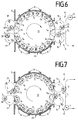
- Fig. 6
- die Darstellung gemäß Fig. 5 bei weitergetaktetem Transportweg,
- Fig. 7
- die Darstellung gemäß Fig. 6 bei weitergetaktetem Transportweg,
- Fig. 8
- Schnittansicht gemäß der Schnittlinie S-S' durch die Karussellschleuse nach Fig. 1,
- Fig. 9
- eine vergrößerte Darstellung eines Teilausschnittes des Umfangs des Schleusenkammerrades mit Dichtungsvorrichtung,
- Fig. 10
- Schnittansicht entlang der Schnittlinie U-U' in Fig. 9 und
- Fig. 11
- einen Ausschnitt des Schleusenkammerrades gemäß Fig. 2 in vergrößerter Darstellung mit Schleusenkammer und zugeordneten Dichtungsvorrichtungen.
- Fig. 1
- the longitudinal section through a lock device with an adjacent treatment chamber and with a schematically illustrated transport path of the workpieces in the treatment chamber,
- Fig. 2
- 1 with lock chamber wheel with associated loading devices with two loaded lock chambers,
- Fig. 3
- 2 in a further clocked transport moment recording of the lock chamber wheel and the loading devices,
- Fig. 4
- 3 with clocked transport moment recording,
- Fig. 5
- 4 with clocked transport route,
- Fig. 6
- 5 with clocked transport route,
- Fig. 7
- 6 with clocked transport route,
- Fig. 8
- Sectional view according to section line SS 'through the carousel lock according to FIG. 1,
- Fig. 9
- an enlarged view of a partial section of the circumference of the lock chamber wheel with sealing device,
- Fig. 10
- Sectional view along section line UU 'in Fig. 9 and
- Fig. 11
- a section of the lock chamber wheel according to FIG. 2 in an enlarged view with lock chamber and associated sealing devices.
Die Schleuseneinrichtung 2 zum kontinuierlichen
Ein- und/oder Ausbringen von Werkstücken in
und/oder aus atmosphärisch voneinander separierten
Räumen 1,4 besteht im wesentlichen aus einem als
Karussellgehäuse 24 ausgebildeten Schleusenkanal
6, der einen Behandlungsraum 4 zum Bearbeiten der
Substrate 3,13 mit dem Außenraum 1 verbindet. Die
Schleuseneinrichtung 2 umfaßt neben dem Karussellgehäuse
24 ein in diesem drehbar gelagertes
Schleusenkammerrad 10, in welchem umfangsseitig
und äquidistant zueinander beabstandet einzelne
Schleusenkammern 7a-7m eingelassen sind. Zum Einschleusen
der Werkstücke 3 von dem Außenraum 1 in
den Behandlungsraum 4 werden die einzelnen Werkstücke
3 in der in den Fig. 2-7 eingezeichneten
Beschickungsstation A über den Transportweg T1
(siehe Fig. 2) an die im Außenraum 1 angeordnete
Beschickungsstation A herangeführt. Die Beschickungsstation
A umfaßt ein Übergabehandlung 15',
dem eine Greifvorrichtung 16' zugeordnet ist. Mittels
der Greifvorrichtung 16' wird das über den
Transportweg T1 herangeführte Substrat 3 vorzugsweise
endseitig ergriffen und durch eine gleichzeitig
erfolgende, radial gerichtete Streckbewegung
der Greifvorrichtung 16' und einer
180°-Drehung des Übergabehandlings 15' gegenüber
einer leeren Schleusenkammer 7a positioniert. Das
Substrat 3 wird dann durch eine in Richtung der
Schleusenkammer 7a gerichtete Streckbewegung der
Greifvorrichtung 16' durch die Schleusenkammeröffnung
20 (siehe Fig. 11) in die Schleusenkammer 7a
eingebracht. Gleichzeitig wird ein beschichtetes
Substrat 13 in analoger Weise, jedoch mit umgekehrtem
Bewegungsablauf mittels des Übergabehandlings
15 und der zugeordneten Greifvorrrichtung 16
aus der Schleusenkammer 7m entnommen. Zum Transport
der in die Schleusenkammern 7a-7m eingebrachten
Substrate 3 bzw. 13 in Richtung der Vakuumkammer
4 bzw. in Richtung des Außenraums 1 dreht das
Schleusenkammerrad 10 entsprechend der in den Fig.
1 bis 8 dargestellten Drehrichtung R. Zur Anpassung
des Drucks in den Schleusenkammern 7a - 7m an
den im Bereich der Übergabestationen A und H bzw.
B und G ist die Karussellkammer 24 über radial
verteilt angeordnete Saugstutzen 8 an nicht dargestellte
Vakuumpumpen angeschlossen. Die Auslegung
der einzelnen Pumpen ist derartig getroffen, daß
die Drücke P1, P2, P3, P4 (siehe Fig. 1) in der Reihenfolge
ihrer Aufzählung abnehmen. Da die einzelnen
Schleusenkammern 7a-7m mittels Dichtungsvorrichtungen
30,32,33,34,35,36 atmosphärisch voneinander
und gleichzeitig vom Außenraum 1 und von dem
Behandlungsraum 4 vollständig getrennt sind, bilden
jeweils sechs Schleusenkammern 7a - 7f bzw. 7g
- 7m jeweils eine sogenannte Druckstufenstrecke,
die das Eindringen von im Außenraum 1 herrschender
Atmosphärenluft in die Behandlungskammer 4 wirksam
unterdrückt und gleichzeitig den Transport von
Substraten 3 bzw. 13 in bzw. aus der Behandlungskammer
1 in den Außenraum 4 ermöglicht bei konstantem
Atmosphärendruck in der Behandlungskammer
4. Die in den Behandlungsraum 4 eingeschleusten
Substrate 3 werden in analoger Weise wie bei der
Beschickungsstation A bzw. der Entladestation H
bei der Übergabestation auf ein in den Figuren
nicht dargestelltes Transportband übergeben. Das
Transportband durchläuft die Transportstrecke T2,
welche in Fig. 1 durch eine strichpunktierte Linie
wiedergegeben ist. Die z. B. mittels einer
schwenkbaren Haltevorrichtung an dem Transportband
lösbar befestigten Substrate 3 werden entlang der
Transportstrecke T2 vor einzelnen Behandlungsstationen
entlangbewegt.The
Bei dem in Fig. 1 dargestellten Ausführungsbeispiel
bestehen die Behandlungsstationen aus einzelnen,
nicht dargestellten Beschichtungsquellen
für die Vakuumbeschichtung. Diese Beschichtungsquellen,
z. B. Verdampfungsquellen und/oder Kathodenzerstäubungsquellen,
erzeugen in bekannter Art
bezogen auf den Quellenmittelpunkt eine radialsymmetrische
dreidimensionale Dichteverteilung 9 des
verdampften bzw. zerstäubten Beschichtungsmaterials.
Entsprechend der von den Prozeßparametern der
Beschichtungsquelle und dem Beschichtungsmaterial
abhängigen Emissionscharakteristik bilden sich sogenannte
25 %-Dichte- bzw. 50 %-Dichte-Verteilungen
9,12 aus, wie in Fig. 1 dargestellt.In the embodiment shown in Fig. 1
the treatment stations consist of individual
Coating sources, not shown
for vacuum coating. These coating sources,
e.g. B. evaporation sources and / or sputtering sources,
generate in a known manner
based on the center of the source, a radially symmetrical one
three-
Um eine gleichmäßige, homogene Beschichtung der
Substrate 3,13 sowohl auf ihren äußeren Wandflächen
als auch auf deren Bodenfläche zu gewährleisten,
werden die Substrate 3,13 zunächst in einer
Wandbeschichtungsposition schräg zu den vorzugsweise
am Boden der Beschichtungskammer 4 angeordneten
Beschichtungsquellen ausgerichtet. Während
des Transports der Substrate 3,13 in der Wandbeschichtungsposition
PS werden die Substrate 3,13 um
ihre Längsachse gedreht, um eine Rundumbeschichtung
zu gewährleisten. Nach erfolgter Beschichtung
der Wandflächen wendet die Transportstrecke T2 um
180° mit einer in der Fig. 1 nicht dargestellten
Wendeeinrichtung, wobei die Substrate 3,13 gleichzeitig
von einer schrägen Beschichtungsposition PS
in eine vertikale Beschichtungsposition PV überführt
werden. Die mit ihrer Bodenfläche zu den Beschichtungsquellen
ausgerichteten Substrate werden
an den Beschichtungsquellen vorbeigeführt, wobei,
wie in Fig. 1 dargestellt, die Substrate 3,13 nunmehr
oberhalb der gleichzeitig in der Wandbeschichtungsposition
PS befindlichen Substrate 3,13
beschichtet werden. Nach Durchlaufen der Transportstrecke
T2 in der Bodenbeschichtungsposition PV
werden die Substrate 3,13 durch eine Wendevorrichtung
11 parallel, jedoch entgegengesetzt zur ersten
Bodenbeschichtungsposition PV an den Beschichtungsquellen
in einer weiteren Bodenbeschichtungsposition
PV entlangbewegt. Im Anschluß an diese
Beschichtungsphase wendet der Transportweg abermals
um 180°, woran sich eine abschließende Beschichtungsphase,
die die Substrate 3 nunmehr in
einer Wandbeschichtungsposition PS durchlaufen, anschließt.In order to ensure a uniform, homogeneous coating of the
Die beschichteten Substrate 13 werden durch das
Transportband entlang der Transportstrecke T2 zur
Übergabestation G transportiert. Nach der Übergabe
der Substrate 13 in die Schleusenkammern 7a - 7m
des Schleusenkammerrades 10 werden die beschichteten
Substrate 13 durch Drehung des Schleusenkammerrades
10 in Drehrichtung R zur Entladestation H
verfahren, wo sie in der oben geschilderten Weise
mittels des in den Fig. 2 bis 7 dargestellten
Übergabehandlings 15 und der Greifvorrichtung 16
der Transportstrecke T1 zugeführt werden (siehe
Fig. 2). The
Die Ausbildung der Schleuseneinrichtung 2 als Karussellschleuse
ist der Fig. 8 zu entnehmen. Die
Schleuseneinrichtung 2 besteht im wesentlichen aus
dem Karussellgehäuse 24, in welches das Schleusenkammerrad
10 auf einer Welle 44 drehbar angeordnet
ist. Die Welle 44 wird mittels zwei in Lagergehäusen
40 bzw. 42 eingepaßten Lagern 48 bzw. 46 gehalten.
In dem Schleusenkammerrad 10 sind einzelne,
jeweils diametral gegenüberliegende und äquidistant
zueinander beabstandete, über den Umfang
des Schleusenkammerrades 10 angeordnete Schleusenkammern
7a - 7m ausgebildet. Wie der Fig. 8 zu
entnehmen ist, sind die Schleusenkammern 7c bzw.
7j stellvertretend für die übrigen Schleusenkammern
mittels Dichtungsvorrichtungen 34,34',36,
32a,32b,50a,50b gegenüber dem Schleusenkanal 41
atmosphärisch druckdicht, insbesondere vakuumdicht,
vorzugsweise hochvakuumdicht getrennt. Die
Dichtungsvorrichtungen 34,34',36,32a,32b,50a,50b
bestehen aus jeweils ober- und unterhalb der einzelnen
Schleusenkammern 7c zw. 7j ausgebildeten
Radialdichtungen 50a,50b, die, wie in den Fig. 9
und 10 abgebildet, gegenüber der Schleusenkanalinnenwand
22 einerseits und Schiebern 32b, die fest
mit dem Schleusenkammerrad 10 und benachbart zu
den Schleusenkammern 7a-7m angeordnet sind, andererseits
atmosphärisch dichten. Der Schieber 32b
wird in einer in einem zugeordneten Schieber 32a
ausgebildeten Kulisse geführt, wobei mittels eines
elastisch verformbaren Ausgleichselements 36 zwischen
dem Schieber 32b und dem Schieber 32a diese
federnd dichtend in Kontakt gehalten werden. Die
Schieber 32a bzw. 32b werden in radialer Richtung
durch Federelemente 34,34' (siehe Fig. 11), welche
durch eine Schraube 35 in dem Schleusenkammerrad
10 fixiert sind, radial nach außen gedrückt, wodurch
die Schieber 32a,32b auch bei Drehung des
Schleusenkammerrades 10 in dynamischem dichtendem
Kontakt mit der Schleusenkammerinnenwand 22 gehalten
werden. Durch die Dichtungsvorrichtung
34,34',36,32a,32b,50a,50b ist somit gewährleistet,
daß die einzelnen Schleusenkammern 7a,7b,... während
des Schleusungsvorganges atmosphärisch und ausreichend
vakuumdichtend voneinander getrennt sind. The formation of the
- 11
- Raum, AußenraumSpace, outside space
- 22nd
- SchleuseneinrichtungLock facility
- 33rd
- Substrat, Behälter, WerkstückSubstrate, container, workpiece
- 44th
- Raum, Behandlungsraum, BeschichtungskammerRoom, treatment room, coating chamber
- 55
- KammerwandChamber wall
- 66
- SchleusenkanalLock channel
- 7a-7m7a-7m
- SchleusenkammerLock chamber
- 88th
- Pumpöffnungen, SaugstutzenPump openings, suction nozzle
- 99
- Bedampfungswolke, 25 %-DichteverteilungEvaporation cloud, 25% density distribution
- 1010th
- Karussellrad, SchleusenkammerradCarousel wheel, lock chamber wheel
- 1111
- WendevorrichtungTurning device
- 1212th
- Bedampfungswolke, 50 %-DichteverteilungEvaporation cloud, 50% density distribution
- 1313
- Substrat, beschichtetCoated substrate
- 1414
- SchleusenkammerwandLock chamber wall
- 15,15'15.15 '
- ÜbergabehandlingTransfer handling
- 16,16'16.16 '
- GreifvorrichtungGripping device
- 17,17'17.17 '
- ÜbergabehandlingTransfer handling
- 18,18'18.18 '
- GreifvorrichtungGripping device
- 19a,b19a, b
- Schleusendeckel, SchleusenbodenLock cover, lock floor
- 2020th
- SchleusenkammeröffnungLock chamber opening
- 2222
- SchleusenkanalinnenwandungLock channel inner wall
- 2424th
- Schleusenkanal, Karussellgehäuse, KarussellkammerLock channel, carousel housing, carousel chamber
- 30,30'30.30 '
- DichtungsvorrichtungSealing device
- 32a,b32a, b
- SchieberSlider
- 33a,b33a, b
- SchieberSlider
- 3434
- FederelementSpring element
- 3535
- Schraube screw
- 3636
- AusgleichselementCompensating element
- 3838
- Zahnradgear
- 4040
- LagerdeckelBearing cap
- 4141
- SchleusenkanalLock channel
- 4242
- LagerdeckelBearing cap
- 4444
- Wellewave
- 4646
- Lagercamp
- 4848
- Lagercamp
- 50a,b50a, b
- RadialdichtungRadial seal
- 5252
- DichtelementSealing element
- 6060
- BeschichtungsquelleCoating source
- AA
- BeschickungsstationLoading station
- BB
- ÜbergabestationTransfer station
- C,D,E,FC, D, E, F
- TransportwegTransport route
- GG
- ÜbergabestationTransfer station
- HH
- EntladestationUnloading station
- RR
- DrehrichtungDirection of rotation
- PS P S
- BehälterwandbeschichtungspositionContainer wall coating position
- PV P V
- BehälterbodenbeschichtungspositionContainer bottom coating position
- T1 T 1
- Transportstrecke / AußenraumTransport route / outside space
- T2 T 2
- Transportstrecke / InnenraumTransport route / interior
Claims (9)
Applications Claiming Priority (4)
| Application Number | Priority Date | Filing Date | Title |
|---|---|---|---|
| DE19807031 | 1998-02-19 | ||
| DE1998107031 DE19807031A1 (en) | 1998-02-19 | 1998-02-19 | Air lock for continuous transfer of articles between sealed chambers, especially for vacuum vapor deposition treatment of plastic bottles |
| DE29802947U | 1998-02-19 | ||
| DE29802947U DE29802947U1 (en) | 1998-02-19 | 1998-02-19 | Lock device for the introduction and / or removal of substrates in and / or from a treatment chamber |
Publications (2)
| Publication Number | Publication Date |
|---|---|
| EP0943699A1 true EP0943699A1 (en) | 1999-09-22 |
| EP0943699B1 EP0943699B1 (en) | 2003-12-17 |
Family
ID=26043994
Family Applications (1)
| Application Number | Title | Priority Date | Filing Date |
|---|---|---|---|
| EP98122354A Expired - Lifetime EP0943699B1 (en) | 1998-02-19 | 1998-11-25 | Load-lock device for transferring substrates in and out of a treatment chamber |
Country Status (4)
| Country | Link |
|---|---|
| US (2) | US6196154B1 (en) |
| EP (1) | EP0943699B1 (en) |
| JP (1) | JPH11323553A (en) |
| DE (1) | DE59810465D1 (en) |
Cited By (7)
| Publication number | Priority date | Publication date | Assignee | Title |
|---|---|---|---|---|
| DE10031800A1 (en) * | 2000-07-04 | 2002-01-24 | Krones Ag | Bottle infeed-outfeed conveyor has housing with feed wheel having pair of seal rings with radial pressure pads to engage wheel |
| DE10205167C1 (en) * | 2002-02-07 | 2003-08-28 | Ardenne Anlagentech Gmbh | Inline vacuum deposition device used for treating substrates has a buffer chamber having an inlet side and an outlet side in the region of a discontinuous transport |
| DE10227637A1 (en) * | 2002-05-24 | 2004-01-15 | Sig Technology Ltd. | Method and device for the plasma treatment of workpieces |
| WO2004042111A2 (en) * | 2002-11-08 | 2004-05-21 | Applied Films Gmbh & Co. Kg | Lock arrangement for a substrate coating installation |
| DE10351330A1 (en) * | 2003-10-31 | 2005-05-25 | Sig Technology Ltd. | Method and device for supplying at least one processing station for a workpiece |
| WO2006136187A1 (en) * | 2005-06-22 | 2006-12-28 | Applied Materials Gmbh & Co. Kg | Device for the successive coating of a number of substrates |
| US8602708B2 (en) | 2008-02-04 | 2013-12-10 | Krones Ag | Lock device for adding and removing containers to and from a vacuum treatment chamber |
Families Citing this family (24)
| Publication number | Priority date | Publication date | Assignee | Title |
|---|---|---|---|---|
| EP0943699B1 (en) * | 1998-02-19 | 2003-12-17 | Applied Films GmbH & Co. KG | Load-lock device for transferring substrates in and out of a treatment chamber |
| US7513953B1 (en) * | 2003-11-25 | 2009-04-07 | Nano Scale Surface Systems, Inc. | Continuous system for depositing films onto plastic bottles and method |
| DE102004012663A1 (en) * | 2004-03-16 | 2005-10-06 | Applied Films Gmbh & Co. Kg | Plant for coating hollow bodies, in particular plastic bottles, with a high-vacuum area and a lock |
| DE102006024638A1 (en) * | 2006-05-19 | 2007-11-22 | Ptm Packaging Tools Machinery Pte.Ltd. | Method and device for treating objects |
| DE102008011774B4 (en) | 2008-02-28 | 2021-12-09 | Krones Aktiengesellschaft | Lock device for bringing containers in and out of a vacuum treatment chamber |
| DE102008012836A1 (en) | 2008-03-06 | 2009-09-10 | Krones Ag | Sluicing device for continuously introducing and removing of objects in and from a vacuum treatment chamber, comprises a rotatable sluicing cylinder with outwardly opened chamber arranged at circumference for the reception of a container |
| DE102008018820A1 (en) | 2008-04-15 | 2009-10-29 | Krones Ag | Airlock system for supplying bottles to vacuum chamber and then removing them comprises cups, on to which lids can be fitted, to which bottles are attached, cups being connected to tubular arms to form rotating wheel |
| US9051650B2 (en) | 2009-01-16 | 2015-06-09 | Marca Machinery, Llc | In-line metallizer assemblies and part-coating conveyor systems incorporating the same |
| US9297064B2 (en) | 2009-01-16 | 2016-03-29 | Marca Machinery, Llc | In-line metallizer assemblies and part-coating conveyor systems incorporating the same |
| JP5835722B2 (en) * | 2009-12-10 | 2015-12-24 | オルボテック エルティ ソラー,エルエルシー | Automatic ranking multi-directional serial processor |
| DE112011100462T5 (en) | 2010-02-05 | 2012-11-22 | Msp Corp. | Fine droplet atomizer for liquid precursor evaporation |
| EP2445003A1 (en) * | 2010-10-25 | 2012-04-25 | Applied Materials, Inc. | Apparatus for providing a rotation carrier magazine, and method of operating thereof |
| EP2799593B1 (en) * | 2011-12-27 | 2020-03-04 | Kirin Beer Kabushiki Kaisha | Apparatus for forming thin film |
| US9022715B2 (en) | 2012-09-18 | 2015-05-05 | Applied Materials, Inc. | Load lock chamber designs for high-throughput processing system |
| RU2543023C2 (en) * | 2012-10-01 | 2015-02-27 | Федеральное государственное бюджетное образовательное учреждение высшего профессионального образования "Владимирский государственный университет имени Александра Григорьевича и Николая Григорьевича Столетовых" (ВлГУ) | Rotor substrate holder |
| US9558975B2 (en) * | 2013-09-20 | 2017-01-31 | Varian Semiconductor Equipment Associates, Inc. | System and method for transferring articles between vacuum and non-vacuum environments |
| US9673076B2 (en) * | 2013-11-05 | 2017-06-06 | Varian Semiconductor Equipment Associates, Inc. | System and method for rotational transfer of articles between vacuum and non-vacuum environments |
| FR3038890B1 (en) * | 2015-07-13 | 2019-08-30 | Coating Plasma Innovation | DEVICE FOR TRANSFERRING OBJECTS BETWEEN AN ATMOSPHERIC PRESSURE ZONE AND A VACUUM ZONE, PROCESSING PLANT AND CORRESPONDING METHOD OF IMPLEMENTATION |
| KR102417929B1 (en) * | 2015-08-07 | 2022-07-06 | 에이에스엠 아이피 홀딩 비.브이. | Apparatus for substrate processing |
| DE102016114292A1 (en) * | 2016-08-02 | 2018-02-08 | Khs Corpoplast Gmbh | Process for coating plastic containers |
| US11694913B2 (en) * | 2018-12-18 | 2023-07-04 | Intevac, Inc. | Hybrid system architecture for thin film deposition |
| US11414748B2 (en) * | 2019-09-25 | 2022-08-16 | Intevac, Inc. | System with dual-motion substrate carriers |
| US20230123586A1 (en) * | 2020-07-30 | 2023-04-20 | Shincron Co., Ltd. | Transfer apparatus and film deposition apparatus using transfer apparatus |
| CN113478705B (en) * | 2021-06-18 | 2022-10-11 | 赤壁市万皇智能设备有限公司 | Spraying circulation line for plastic part production |
Citations (5)
| Publication number | Priority date | Publication date | Assignee | Title |
|---|---|---|---|---|
| US3260383A (en) * | 1964-08-04 | 1966-07-12 | Vacuum Processes Inc | Method and apparatus for loading and unloading a high vacuum process chamber |
| FR1496205A (en) * | 1966-08-18 | 1967-09-29 | S E A V O M | Device for the vacuum treatment of various parts and in particular parts in the form of rolling bodies |
| US3894926A (en) * | 1973-02-09 | 1975-07-15 | Lee Jau Yien | In-out transporter for an enclosed chamber |
| JPS58153345A (en) * | 1982-03-05 | 1983-09-12 | Jeol Ltd | Specimen feeding device |
| EP0816529A1 (en) * | 1996-07-04 | 1998-01-07 | Leybold Systems GmbH | Vacuum treatment apparatus for coating of substrates |
Family Cites Families (28)
| Publication number | Priority date | Publication date | Assignee | Title |
|---|---|---|---|---|
| US812154A (en) * | 1905-04-01 | 1906-02-06 | Arthur C Lea | Continuous steam-cooker. |
| US1808017A (en) * | 1930-03-01 | 1931-06-02 | Frank D Chapman | Valve for cookers |
| US1969771A (en) * | 1931-08-22 | 1934-08-14 | American Can Co | Vacuum machine |
| US2393997A (en) * | 1941-12-11 | 1946-02-05 | American Can Co | Transfer mechanism |
| US2585472A (en) * | 1946-12-05 | 1952-02-12 | Kennedy Vera Alward | Rotary transfer valve |
| US2688416A (en) * | 1949-10-21 | 1954-09-07 | Kamyr Ab | Rotary valve |
| US2858212A (en) * | 1956-02-13 | 1958-10-28 | Condi Engineering Corp | Wood chip feeders |
| US2960245A (en) * | 1958-01-06 | 1960-11-15 | Knapp Hans John | Material handling valve |
| US3219393A (en) * | 1961-10-05 | 1965-11-23 | Bauer Bros Co | Rotary valve |
| US3556355A (en) * | 1968-05-28 | 1971-01-19 | Basic Inc | Pressure sealed rotary feeder |
| CH573985A5 (en) | 1973-11-22 | 1976-03-31 | Balzers Patent Beteilig Ag | |
| US4180188A (en) * | 1975-11-18 | 1979-12-25 | Kokkoman Shoyu Co., Ltd. | Sealing structure for rotary valves |
| US4179043A (en) * | 1978-01-03 | 1979-12-18 | Koppers Company, Inc. | Rotary valve apparatus |
| US4268205A (en) * | 1979-06-07 | 1981-05-19 | Mayfran, Div. Of Fischer Industries, Inc. | Method and apparatus for removing material from the ends of a rotary air lock |
| JPS62164881A (en) | 1986-01-14 | 1987-07-21 | Canon Inc | Deposited film forming device |
| DE3827343A1 (en) | 1988-08-12 | 1990-02-15 | Leybold Ag | DEVICE ACCORDING TO THE CAROUSEL PRINCIPLE FOR COATING SUBSTRATES |
| DE3735284A1 (en) | 1987-10-17 | 1989-04-27 | Leybold Ag | DEVICE ACCORDING TO THE CAROUSEL PRINCIPLE FOR COATING SUBSTRATES |
| JPH05331642A (en) | 1992-06-01 | 1993-12-14 | Hitachi Ltd | Multichamber type sputtering device |
| US5405231A (en) * | 1993-08-02 | 1995-04-11 | The United States Of America As Represented By The Department Of Energy | Conveyor with rotary airlock apparatus |
| US5521351A (en) * | 1994-08-30 | 1996-05-28 | Wisconsin Alumni Research Foundation | Method and apparatus for plasma surface treatment of the interior of hollow forms |
| US6086728A (en) * | 1994-12-14 | 2000-07-11 | Schwartz; Vladimir | Cross flow metalizing of compact discs |
| JPH0941143A (en) | 1995-08-03 | 1997-02-10 | Shin Etsu Chem Co Ltd | Production of recording medium |
| US5630691A (en) * | 1995-08-14 | 1997-05-20 | Mac Equipment, Inc. | Rotary airlock valve |
| JP3752679B2 (en) | 1995-11-24 | 2006-03-08 | 石川島播磨重工業株式会社 | Vacuum seal device for sheet material |
| DE19624609B4 (en) | 1996-06-20 | 2009-04-16 | Leybold Optics Gmbh | Vacuum treatment system for applying thin layers to substrates, for example to headlight reflectors |
| US6223683B1 (en) * | 1997-03-14 | 2001-05-01 | The Coca-Cola Company | Hollow plastic containers with an external very thin coating of low permeability to gases and vapors through plasma-assisted deposition of inorganic substances and method and system for making the coating |
| EP0943699B1 (en) * | 1998-02-19 | 2003-12-17 | Applied Films GmbH & Co. KG | Load-lock device for transferring substrates in and out of a treatment chamber |
| DE19807032A1 (en) * | 1998-02-19 | 1999-08-26 | Leybold Systems Gmbh | Vapor coating of cylindrical substrates e.g. silicon dioxide coating for sealing plastic carbonated drinks bottles |
-
1998
- 1998-11-25 EP EP98122354A patent/EP0943699B1/en not_active Expired - Lifetime
- 1998-11-25 DE DE59810465T patent/DE59810465D1/en not_active Expired - Lifetime
-
1999
- 1999-02-12 US US09/249,445 patent/US6196154B1/en not_active Expired - Lifetime
- 1999-02-19 JP JP11041740A patent/JPH11323553A/en active Pending
-
2000
- 2000-08-03 US US09/631,940 patent/US6335054B1/en not_active Expired - Lifetime
Patent Citations (5)
| Publication number | Priority date | Publication date | Assignee | Title |
|---|---|---|---|---|
| US3260383A (en) * | 1964-08-04 | 1966-07-12 | Vacuum Processes Inc | Method and apparatus for loading and unloading a high vacuum process chamber |
| FR1496205A (en) * | 1966-08-18 | 1967-09-29 | S E A V O M | Device for the vacuum treatment of various parts and in particular parts in the form of rolling bodies |
| US3894926A (en) * | 1973-02-09 | 1975-07-15 | Lee Jau Yien | In-out transporter for an enclosed chamber |
| JPS58153345A (en) * | 1982-03-05 | 1983-09-12 | Jeol Ltd | Specimen feeding device |
| EP0816529A1 (en) * | 1996-07-04 | 1998-01-07 | Leybold Systems GmbH | Vacuum treatment apparatus for coating of substrates |
Non-Patent Citations (1)
| Title |
|---|
| PATENT ABSTRACTS OF JAPAN vol. 007, no. 272 (E - 214) 3 December 1983 (1983-12-03) * |
Cited By (10)
| Publication number | Priority date | Publication date | Assignee | Title |
|---|---|---|---|---|
| DE10031800A1 (en) * | 2000-07-04 | 2002-01-24 | Krones Ag | Bottle infeed-outfeed conveyor has housing with feed wheel having pair of seal rings with radial pressure pads to engage wheel |
| DE10031800C2 (en) * | 2000-07-04 | 2002-08-08 | Krones Ag | Device for introducing and / or discharging objects, in particular containers, into or from a treatment room |
| DE10205167C1 (en) * | 2002-02-07 | 2003-08-28 | Ardenne Anlagentech Gmbh | Inline vacuum deposition device used for treating substrates has a buffer chamber having an inlet side and an outlet side in the region of a discontinuous transport |
| DE10205167C5 (en) * | 2002-02-07 | 2007-01-18 | Von Ardenne Anlagentechnik Gmbh | In-line vacuum coating system for the intermediate treatment of substrates |
| DE10227637A1 (en) * | 2002-05-24 | 2004-01-15 | Sig Technology Ltd. | Method and device for the plasma treatment of workpieces |
| WO2004042111A2 (en) * | 2002-11-08 | 2004-05-21 | Applied Films Gmbh & Co. Kg | Lock arrangement for a substrate coating installation |
| WO2004042111A3 (en) * | 2002-11-08 | 2005-01-27 | Applied Films Gmbh & Co Kg | Lock arrangement for a substrate coating installation |
| DE10351330A1 (en) * | 2003-10-31 | 2005-05-25 | Sig Technology Ltd. | Method and device for supplying at least one processing station for a workpiece |
| WO2006136187A1 (en) * | 2005-06-22 | 2006-12-28 | Applied Materials Gmbh & Co. Kg | Device for the successive coating of a number of substrates |
| US8602708B2 (en) | 2008-02-04 | 2013-12-10 | Krones Ag | Lock device for adding and removing containers to and from a vacuum treatment chamber |
Also Published As
| Publication number | Publication date |
|---|---|
| DE59810465D1 (en) | 2004-01-29 |
| US6196154B1 (en) | 2001-03-06 |
| US6335054B1 (en) | 2002-01-01 |
| JPH11323553A (en) | 1999-11-26 |
| EP0943699B1 (en) | 2003-12-17 |
Similar Documents
| Publication | Publication Date | Title |
|---|---|---|
| EP0943699B1 (en) | Load-lock device for transferring substrates in and out of a treatment chamber | |
| DE102004036170B4 (en) | Vacuum coating system and method for vacuum coating and their use | |
| DE112006001996B4 (en) | Vacuum processing apparatus | |
| EP1727925B1 (en) | Method for forming thin silicon nitride layers on the surface of substrates | |
| DE4324320B4 (en) | Method and device for producing a thin-film photovoltaic conversion device | |
| DE4116554C2 (en) | Transport method and device for clean room conditions | |
| EP0307539A2 (en) | Process and apparatus for coating substrates | |
| WO2006069774A2 (en) | Vacuum deposition system | |
| WO2010060646A1 (en) | Method for producing semiconductor layers and coated substrates treated with elemental selenium and/or sulfur, in particular flat substrates | |
| DE19807032A1 (en) | Vapor coating of cylindrical substrates e.g. silicon dioxide coating for sealing plastic carbonated drinks bottles | |
| DE102009004493B3 (en) | Vacuum coating system and method for operating a vacuum coating system | |
| EP0984076B1 (en) | Apparatus for coating substrates in a vacuum chamber | |
| DE19522934A1 (en) | PTFE lubricated, recirculating ball screw, useful in semiconductor mfr. | |
| DE102007058052B4 (en) | Vacuum coating system | |
| EP0905275B1 (en) | Apparatus for coating an essentially flat, disc-shaped substrate | |
| EP0837154B1 (en) | Vacuum coating apparatus | |
| DE4313284A1 (en) | Slot lock for introducing or discharging substrates from one treatment chamber into an adjacent one | |
| EP1618056A1 (en) | Device for transporting a flat substrate in a vacuum chamber | |
| DE19807031A1 (en) | Air lock for continuous transfer of articles between sealed chambers, especially for vacuum vapor deposition treatment of plastic bottles | |
| DE102004015216B4 (en) | Process and modular assembly to modify the surface of a metal substrate surface by exposure to plasma | |
| WO2004042111A2 (en) | Lock arrangement for a substrate coating installation | |
| DE102009009022A1 (en) | Method and device for coating flat substrates with chalcogens | |
| DE102014107636B4 (en) | Vacuum processing system | |
| DE102008011774B4 (en) | Lock device for bringing containers in and out of a vacuum treatment chamber | |
| DE102016109510B4 (en) | Vacuum processing plant and method for the batch introduction and removal of substrates |
Legal Events
| Date | Code | Title | Description |
|---|---|---|---|
| PUAI | Public reference made under article 153(3) epc to a published international application that has entered the european phase |
Free format text: ORIGINAL CODE: 0009012 |
|
| AK | Designated contracting states |
Kind code of ref document: A1 Designated state(s): DE FR GB IT NL SE |
|
| AX | Request for extension of the european patent |
Free format text: AL;LT;LV;MK;RO;SI |
|
| 17P | Request for examination filed |
Effective date: 19991215 |
|
| AKX | Designation fees paid |
Free format text: DE FR GB IT NL SE |
|
| RAP1 | Party data changed (applicant data changed or rights of an application transferred) |
Owner name: APPLIED FILMS GMBH & CO. KG |
|
| 17Q | First examination report despatched |
Effective date: 20020313 |
|
| GRAH | Despatch of communication of intention to grant a patent |
Free format text: ORIGINAL CODE: EPIDOS IGRA |
|
| GRAS | Grant fee paid |
Free format text: ORIGINAL CODE: EPIDOSNIGR3 |
|
| GRAA | (expected) grant |
Free format text: ORIGINAL CODE: 0009210 |
|
| AK | Designated contracting states |
Kind code of ref document: B1 Designated state(s): DE FR GB IT NL SE |
|
| REG | Reference to a national code |
Ref country code: GB Ref legal event code: FG4D Free format text: NOT ENGLISH |
|
| GBT | Gb: translation of ep patent filed (gb section 77(6)(a)/1977) |
Effective date: 20031217 |
|
| REG | Reference to a national code |
Ref country code: SE Ref legal event code: TRGR |
|
| REF | Corresponds to: |
Ref document number: 59810465 Country of ref document: DE Date of ref document: 20040129 Kind code of ref document: P |
|
| ET | Fr: translation filed | ||
| PLBE | No opposition filed within time limit |
Free format text: ORIGINAL CODE: 0009261 |
|
| STAA | Information on the status of an ep patent application or granted ep patent |
Free format text: STATUS: NO OPPOSITION FILED WITHIN TIME LIMIT |
|
| 26N | No opposition filed |
Effective date: 20040920 |
|
| NLT1 | Nl: modifications of names registered in virtue of documents presented to the patent office pursuant to art. 16 a, paragraph 1 |
Owner name: APPLIED MATERIALS GMBH & CO. KG |
|
| REG | Reference to a national code |
Ref country code: FR Ref legal event code: CD |
|
| PGFP | Annual fee paid to national office [announced via postgrant information from national office to epo] |
Ref country code: DE Payment date: 20121121 Year of fee payment: 15 Ref country code: FR Payment date: 20121130 Year of fee payment: 15 |
|
| PGFP | Annual fee paid to national office [announced via postgrant information from national office to epo] |
Ref country code: SE Payment date: 20121120 Year of fee payment: 15 Ref country code: IT Payment date: 20121127 Year of fee payment: 15 Ref country code: GB Payment date: 20121120 Year of fee payment: 15 |
|
| PGFP | Annual fee paid to national office [announced via postgrant information from national office to epo] |
Ref country code: NL Payment date: 20121120 Year of fee payment: 15 |
|
| REG | Reference to a national code |
Ref country code: NL Ref legal event code: V1 Effective date: 20140601 |
|
| REG | Reference to a national code |
Ref country code: SE Ref legal event code: EUG |
|
| GBPC | Gb: european patent ceased through non-payment of renewal fee |
Effective date: 20131125 |
|
| REG | Reference to a national code |
Ref country code: FR Ref legal event code: ST Effective date: 20140731 |
|
| REG | Reference to a national code |
Ref country code: DE Ref legal event code: R119 Ref document number: 59810465 Country of ref document: DE Effective date: 20140603 |
|
| PG25 | Lapsed in a contracting state [announced via postgrant information from national office to epo] |
Ref country code: SE Free format text: LAPSE BECAUSE OF NON-PAYMENT OF DUE FEES Effective date: 20131126 Ref country code: IT Free format text: LAPSE BECAUSE OF NON-PAYMENT OF DUE FEES Effective date: 20131125 Ref country code: DE Free format text: LAPSE BECAUSE OF NON-PAYMENT OF DUE FEES Effective date: 20140603 Ref country code: NL Free format text: LAPSE BECAUSE OF NON-PAYMENT OF DUE FEES Effective date: 20140601 |
|
| PG25 | Lapsed in a contracting state [announced via postgrant information from national office to epo] |
Ref country code: FR Free format text: LAPSE BECAUSE OF NON-PAYMENT OF DUE FEES Effective date: 20131202 Ref country code: GB Free format text: LAPSE BECAUSE OF NON-PAYMENT OF DUE FEES Effective date: 20131125 |